This CE Center article is no longer eligible for receiving credits.
Building codes and green building standards are continuing to raise the bar on energy efficiency and high performance in buildings. This is achieved in wood-framed buildings by addressing both insulation levels and air tightness. While this is a positive trend, there are some notable wall design issues to address. Specifically, determining the best amount and type of insulation to use may be unclear, particularly in light of controlling water vapor or moisture that can become trapped in constructed wall assemblies. This is especially true in the case of providing exterior continuous insulation as part of a framed exterior wall. Codes and best practices suggest different amounts of continuous insulation for different climate zones. There is also concern that the continuous insulation can impact the ability of the wall to “breathe” and release any trapped moisture from within the assembly so, in some cases, it can impact the choice of an interior vapor retarder on the warm, inner side of the building. All of these variables and options have led to some significant confusion concerning the best way to properly address both code-required exterior thermal insulation and vapor management in wall assemblies. This course will help provide clarity on the differences between the varied prescriptive code requirements for continuous insulation in different climate zones, along with principles and choices related to proper moisture management.

All images courtesy of Huber Engineered Woods LLC, except as noted
The energy performance of exterior walls is enhanced by including exterior continuous insulation. With new integrated sheathing, this layer is built in to the back of the nailable sheathing that goes directly against the framing.
Why Continuous Insulation?
Framed wall construction, whether using wood studs or metal studs, has an inherent weakness from a thermal efficiency point of view. Simply put, the framing allows more heat to flow through it than insulation does. This is quite observable and measurable using standard techniques that test different materials for the amount of heat flow or heat transfer through them. Those tests are grounded in the fundamental laws of physics and thermodynamics that, among other things, point out that heat always seeks a balance by flowing from a warm source to a cooler place.
Heat Transfer
The means to measure heat transfer in building products is based on U-factors, which indicate how many British thermal units (BTUs) of energy pass through a defined size of material (i.e., one square foot) over time (specifically one hour) for each degree Fahrenheit in temperature difference. (The greater the difference in temperature between the two sides of the material, the faster or more intensely that heat flows.) In order to determine how much heat is transferred through any specific material, its U-factor is determined by testing that material on a square-foot basis over time, while measuring the temperature difference between the two sides. The resulting number is generally a decimal (e.g., 0.5), with smaller numbers indicating small amounts of heat transfer (think insulation) and higher numbers indicating more heat transfer (think conductive metal). Applying this to a building, the fundamental formula used is (U x A) x dT where U= the tested U-factor for one square foot of material, A= the area in square feet installed in a construction assembly, and dT is the design or actual temperature difference between indoors and outdoors. All thermal energy calculations in building enclosures (i.e., walls, roofs, etc.) are based on this fundamental formula.
It is worth pointing out that while scientists and engineers like to work and think in fractional U-factors, most of the general population prefers whole numbers, which has made R-values the popular means to talk about thermal capabilities of materials. This is still very legitimate since the testing and calculation process is exactly the same. The difference is that instead of indicating the results as heat transfer through a material, they are reported as heat resistance—the direct inverse to heat flow. Since U-factors and R-values are the multiplicative inverse of each other, to convert U-factors to R-values and vice versa, you divide one by the number you are attempting to convert. So, an insulating material with a tested heat flow U-factor of .05 is easily then divided into 1 (1/.05) to indicate a resistance R-value of R-20. Similarly, an insulation product with an R-value of R-20 is converted to a U-factor as 1/20 = .05. Hence, it has become common for individual materials and products to be promoted and marketed based on their R-values. It is also somewhat easier to think in terms of higher R-values equaling greater resistance to heat flow, which essentially translates into better energy performance in building enclosures. From a calculation point of view, R-values of multiple materials can be added together to determine a total R-value, but U-factors cannot be combined together.
Thermal Bridging
As most design professionals are well aware, construction assemblies are very rarely monolithic. Rather, they require different materials that are assembled to make up the overall construction. In framed exterior walls, the framing members are spaced at 16 or 24 inches on center with upper and lower plates, not to mention additional framing around door or window openings. This framing defines the fundamental thickness of the wall and the spaces between or around the framing are commonly filled with insulation. Then, continuous layers of interior and exterior sheathing, such as gypsum board or wood panel products, cover the framed and insulated areas to create a wall ready for finishing. In order to accurately determine the true thermal performance of this typically constructed wall, at least two calculations are needed: one based on cutting a cross section through the framing and the other based on a cross section through the insulation. Then the resulting numbers need to be applied to the appropriate percentage of the total wall area to produce a weighted average UA for the whole wall.
In typical situations, the framing can account for 20 to 30 percent of the area of any given exterior wall with only about 70 to 80 percent of the wall area actually containing insulation. Since the framed sections will not have the same U-factor/R-value of the insulation, the thermal effectiveness of the wall is directly compromised. It is easy to ask, is this 20 to 30 percent framing area really a big deal? It turns out that the answer is yes. Any building material, including framing or sheathing, that has a capacity to transfer heat more than insulation will follow the laws of physics and do so. In this case, every stud or other solid structural item, like floor band joists, columns, etc., is acting as a breach in the insulated wall, allowing heat to transfer through it. This solid connection between the warm side and the cool side of an assembly acts as a “thermal bridge,” allowing heat to flow freely between the sections where the insulation is present.
To illustrate this, let’s look at U-Factor Example 1 showing 2-by-6 wood stud framing at 16 inches on center with R-20 insulation between the studs. We have identified the section through the studs as A1 and the section through the insulation as A2. Entering the tested and known R-values (from independent sources) of the various materials, we find that the total R-value through the studs is only R-7.95 (U-0.126) compared to an R-21.07 (U-0.048) through the insulated portions. Assuming 22 percent framing and 78 percent insulating areas, the weighted average for the total wall produces an overall effective R-value of R-15.34 (U-0.065). This is a reduction in overall thermal performance of more than 27 percent due to the thermal bridging of the studs, which is quite significant.
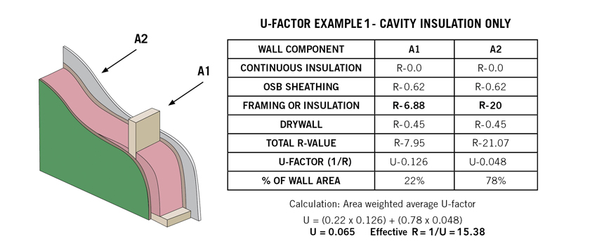
Calculating the thermal performance of framed walls with only cavity insulation needs to account for the heat transfer through the studs as well as through the insulation.
Building codes and green building standards are continuing to raise the bar on energy efficiency and high performance in buildings. This is achieved in wood-framed buildings by addressing both insulation levels and air tightness. While this is a positive trend, there are some notable wall design issues to address. Specifically, determining the best amount and type of insulation to use may be unclear, particularly in light of controlling water vapor or moisture that can become trapped in constructed wall assemblies. This is especially true in the case of providing exterior continuous insulation as part of a framed exterior wall. Codes and best practices suggest different amounts of continuous insulation for different climate zones. There is also concern that the continuous insulation can impact the ability of the wall to “breathe” and release any trapped moisture from within the assembly so, in some cases, it can impact the choice of an interior vapor retarder on the warm, inner side of the building. All of these variables and options have led to some significant confusion concerning the best way to properly address both code-required exterior thermal insulation and vapor management in wall assemblies. This course will help provide clarity on the differences between the varied prescriptive code requirements for continuous insulation in different climate zones, along with principles and choices related to proper moisture management.
All images courtesy of Huber Engineered Woods LLC, except as noted
The energy performance of exterior walls is enhanced by including exterior continuous insulation. With new integrated sheathing, this layer is built in to the back of the nailable sheathing that goes directly against the framing.
Why Continuous Insulation?
Framed wall construction, whether using wood studs or metal studs, has an inherent weakness from a thermal efficiency point of view. Simply put, the framing allows more heat to flow through it than insulation does. This is quite observable and measurable using standard techniques that test different materials for the amount of heat flow or heat transfer through them. Those tests are grounded in the fundamental laws of physics and thermodynamics that, among other things, point out that heat always seeks a balance by flowing from a warm source to a cooler place.
Heat Transfer
The means to measure heat transfer in building products is based on U-factors, which indicate how many British thermal units (BTUs) of energy pass through a defined size of material (i.e., one square foot) over time (specifically one hour) for each degree Fahrenheit in temperature difference. (The greater the difference in temperature between the two sides of the material, the faster or more intensely that heat flows.) In order to determine how much heat is transferred through any specific material, its U-factor is determined by testing that material on a square-foot basis over time, while measuring the temperature difference between the two sides. The resulting number is generally a decimal (e.g., 0.5), with smaller numbers indicating small amounts of heat transfer (think insulation) and higher numbers indicating more heat transfer (think conductive metal). Applying this to a building, the fundamental formula used is (U x A) x dT where U= the tested U-factor for one square foot of material, A= the area in square feet installed in a construction assembly, and dT is the design or actual temperature difference between indoors and outdoors. All thermal energy calculations in building enclosures (i.e., walls, roofs, etc.) are based on this fundamental formula.
It is worth pointing out that while scientists and engineers like to work and think in fractional U-factors, most of the general population prefers whole numbers, which has made R-values the popular means to talk about thermal capabilities of materials. This is still very legitimate since the testing and calculation process is exactly the same. The difference is that instead of indicating the results as heat transfer through a material, they are reported as heat resistance—the direct inverse to heat flow. Since U-factors and R-values are the multiplicative inverse of each other, to convert U-factors to R-values and vice versa, you divide one by the number you are attempting to convert. So, an insulating material with a tested heat flow U-factor of .05 is easily then divided into 1 (1/.05) to indicate a resistance R-value of R-20. Similarly, an insulation product with an R-value of R-20 is converted to a U-factor as 1/20 = .05. Hence, it has become common for individual materials and products to be promoted and marketed based on their R-values. It is also somewhat easier to think in terms of higher R-values equaling greater resistance to heat flow, which essentially translates into better energy performance in building enclosures. From a calculation point of view, R-values of multiple materials can be added together to determine a total R-value, but U-factors cannot be combined together.
Thermal Bridging
As most design professionals are well aware, construction assemblies are very rarely monolithic. Rather, they require different materials that are assembled to make up the overall construction. In framed exterior walls, the framing members are spaced at 16 or 24 inches on center with upper and lower plates, not to mention additional framing around door or window openings. This framing defines the fundamental thickness of the wall and the spaces between or around the framing are commonly filled with insulation. Then, continuous layers of interior and exterior sheathing, such as gypsum board or wood panel products, cover the framed and insulated areas to create a wall ready for finishing. In order to accurately determine the true thermal performance of this typically constructed wall, at least two calculations are needed: one based on cutting a cross section through the framing and the other based on a cross section through the insulation. Then the resulting numbers need to be applied to the appropriate percentage of the total wall area to produce a weighted average UA for the whole wall.
In typical situations, the framing can account for 20 to 30 percent of the area of any given exterior wall with only about 70 to 80 percent of the wall area actually containing insulation. Since the framed sections will not have the same U-factor/R-value of the insulation, the thermal effectiveness of the wall is directly compromised. It is easy to ask, is this 20 to 30 percent framing area really a big deal? It turns out that the answer is yes. Any building material, including framing or sheathing, that has a capacity to transfer heat more than insulation will follow the laws of physics and do so. In this case, every stud or other solid structural item, like floor band joists, columns, etc., is acting as a breach in the insulated wall, allowing heat to transfer through it. This solid connection between the warm side and the cool side of an assembly acts as a “thermal bridge,” allowing heat to flow freely between the sections where the insulation is present.
To illustrate this, let’s look at U-Factor Example 1 showing 2-by-6 wood stud framing at 16 inches on center with R-20 insulation between the studs. We have identified the section through the studs as A1 and the section through the insulation as A2. Entering the tested and known R-values (from independent sources) of the various materials, we find that the total R-value through the studs is only R-7.95 (U-0.126) compared to an R-21.07 (U-0.048) through the insulated portions. Assuming 22 percent framing and 78 percent insulating areas, the weighted average for the total wall produces an overall effective R-value of R-15.34 (U-0.065). This is a reduction in overall thermal performance of more than 27 percent due to the thermal bridging of the studs, which is quite significant.
Calculating the thermal performance of framed walls with only cavity insulation needs to account for the heat transfer through the studs as well as through the insulation.
Continuous Insulation
What is the solution to all of these thermal bridges and lack of performance in the wall system? For those who want to stay with the tried and proven method of framed construction, the answer is in providing continuous insulation (CI) that is not interrupted by the framing. Such insulation is commonly thought of as a rigid foam insulation made into board products, foamed in place on site, or in the newest instances, included as an integrated part of the exterior wall sheathing. In any of these cases, in order to make the insulation truly continuous, it needs to be placed either on the inside or outside face of the studs, with the outer surface usually being preferable. An outer face installation allows for complete coverage of all framing, including headers, corners, floors, and other structural elements. It also doesn’t interfere with interior dimensions or finishing and, as we will see, can be managed well for moisture and water vapor in a wall assembly.
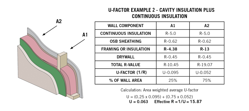
When continuous insulation is added to a framed wall assembly, its R-value is added to both the R-value of the framing and the stud cavity insulation.
So how much of an impact can this continuous insulation have on the wall? Let’s look at another U-factor calculation example but this time, let’s see the effects of continuous insulation over the outside of the wall assembly. In U-Factor Example 2, we will use 2-by-4 framing at 16 inches on center with R-13 insulation in the cavities (instead of the previous 2-by-6 framing with R-20). Again, we need to calculate the A1 and A2 performance through the studs and the cavity insulation respectively. However, this time we are able to add in R-5 to both cases in order to account for the layer of continuous insulation that covers the entire wall. The results in this scenario show that the total R-value through the studs plus the continuous insulation and sheathing has increased to R-10.45 (U-0.95) compared to an R-19.07 (U-0.052) through the insulated portions. Assuming here 25 percent framing and 75 percent insulating areas, the weighted average for this total wall is an overall effective R-value of R-15.93 (U-0.063). Comparing this example to the first one, we find virtually the same overall results using 2-by-4 framing with R-13 cavity insulation and R-5 continuous insulation as using 2-by-6 framing with R-20 cavity insulation. The 2-by-6 cavity insulation alone has to have a higher R-value (R-20) than the sum of the 2-by-4 cavity insulation plus the continuous insulation (R-13 + R-5 = R-18) in order to make up for the thermal bridging of the studs and still perform as well overall.
Continuous Insulation Choices
As noted, there are choices in the type of materials that can be selected and specified as continuous insulation. Over the past few decades, nonstructural insulating sheathing products of different types have come on the market and are now available in common construction sizes and in varying thicknesses. These products are essentially rigid foam insulation that may or may not have a facing depending on the material. They are foamed from plastics such as polystyrene, polyurethane, and polyisocyanurate, with each carrying different thermal and physical characteristics. Of these, polyisocyanurate (or simply “polyiso”) has become popular because of its performance. According to the Polyisocyanurate Manufacturers Association (PIMA), polyiso has the highest R-value per inch of any rigid foam board insulation. It also points out that polyiso is unique in that the R-value per inch increases with the thickness of the foam, so 3 inches of polyiso has a higher R-value per inch than 2 inches. This superior performance compared to other foam insulation products can mean less material is needed overall, making it very cost effective.
Of course, in framed walls, there is also the need for solid sheathing over the studs that can provide structural bracing for the wall and a nailbase for the attachment of siding, cladding, brick ties, etc. Most foam sheathing products aren’t rated to be structural and don’t necessarily provide a good nail base. That usually means that the foam insulation is put up after structural sheathing goes over the studs. In some cases, the structural sheathing may only be required in strategic locations, such as corners, and thicker rigid insulation can be put up in between. However, in some cases, another layer is needed to provide a nail base or else the exterior cladding needs to be carefully attached to the studs. This multistep process obviously adds to the labor involved in constructing the wall, but it also requires attention to the fastening pattern.

Continuous insulation is available as part of an exterior sheathing system that can be used as a structural panel when properly fastened according to the manufacturer’s instructions.
One of the more simplified choices to address both the structural and thermal needs of exterior continuous insulation is a single product that contains both a structural sheathing panel and an integrated layer of continuous insulation. This type of nail-base insulation product has been commonly used on commercial roofing systems for years, but it has taken some engineering and development for it to be ready for use on walls. As a single, combined product, it eliminates a labor step by installing both continuous insulation and a structural, nailable sheathing all at once. Some are even preprinted with the manufacturer’s recommended nail patterns to take the guess work out of assuring appropriate structural strength. And to further assure structural integrity, the best option is to rely on a product that has been tested as a complete, combined panel under laboratory conditions. One engineered wood exterior sheathing manufacturer has obtained third-party documentation through the International Code Council’s Evaluation Services to be used as an acceptable structural panel.1 From a thermal performance standpoint, this multifunctional, single-panel exterior sheathing system product is commonly available with different thicknesses of continuous insulation ranging from R-3 to R-12.
Continuous Insulation in Codes and Standards
With the clear benefits demonstrated in using continuous insulation and its increasing availability as a practical material, it is not surprising that building and energy codes are not only recognizing it, but in some cases are now requiring it to be used. In fact, some designers might say they are surprised that it hasn’t happened sooner. For purposes of our discussion here, we will be referring to the 2015 codes published by the International Code Council, specifically the 2015 International Residential Code (IRC), the 2015 International Building Code (IBC), and the 2015 International Energy Conservation Code (IECC).
2015 IRC and IBC
As general construction codes, both the IRC and the IBC have always been similar in intent (i.e., general health, safety, and welfare of people in buildings) but different in their focus on different types or classes of structures. The IRC covers detached and attached one- and two-family residential units, including attached townhouses, up to three stories in height. The IBC covers everything else, including residential buildings, such as multifamily occupancies like apartments, dormitories, boarding houses, hotels, and motels.
Both the IRC and IBC allow for either metal- or wood-framed wall construction with particular limits based on fire and safety criteria. They also both address durability and protection of the construction assemblies by requiring a weather-resistant barrier (WRB) over exterior wall sheathing and in some climate zones, a warm-side vapor retarder. Both of these are intended to protect the wall assembly from being damaged by water or weather intrusion, which could lead to possible decay or mold that is not only a concern for building owners but also a possible health risk to occupants.
2015 IECC
This latest version of the Energy Conservation Code is essentially two documents in one—it contains six chapters for residential buildings and a separate but similar six chapters for commercial building energy conservation requirements. There are several critical points to understand with this code:
- Residential vs. Commercial: The applicability of the IECC residential portion is actually different from the distinction between the IBC and IRC. Under the IECC, the residential portion applies not only to detached one- and two-family dwellings and multiple single-family dwellings (townhouses) as in the IRC, but also to Occupancy Group R-2, R-3, and R-4 buildings that are permanent residences and are three stories or less in height above the grade plane. These occupancy group buildings are defined in the IBC to include things like apartment buildings, dormitories, halfway houses, and long-term care facilities. The rationale behind this distinction appears to be that these permanent, residential classifications up to three stories in height are more akin to residential construction and therefore should be subject to the more appropriate and stringent requirements of the residential portion of the IECC. R-2, R-3, and R-4 buildings that are more transient in nature or over three stories in height are to follow the commercial provisions of the IECC.
- Climate Zones: The IECC recognizes eight different climate zones (simply numbered 1 to 8) across all states and counties in the United States. These climate zones are calculated on the basis of the need for heating or cooling using common degree-day methodology. Climate zones 1 and 2 show up in the warmest areas in Florida and the Gulf Coast, plus an area around southern Arizona. Climate zone 3 covers a varying-sized swath from the southeastern United States across to much of California. Climate zones 4, 5, and 6 cover most of the country from coast to coast above the southern states. Climate zones 7 and 8 identify the coldest areas in places like northern Maine, Minnesota, some places in the Rocky Mountains, and in Alaska. Some portions of the country are further identified as marine, dry, moist, or warm-humid based on criteria identified in the code.
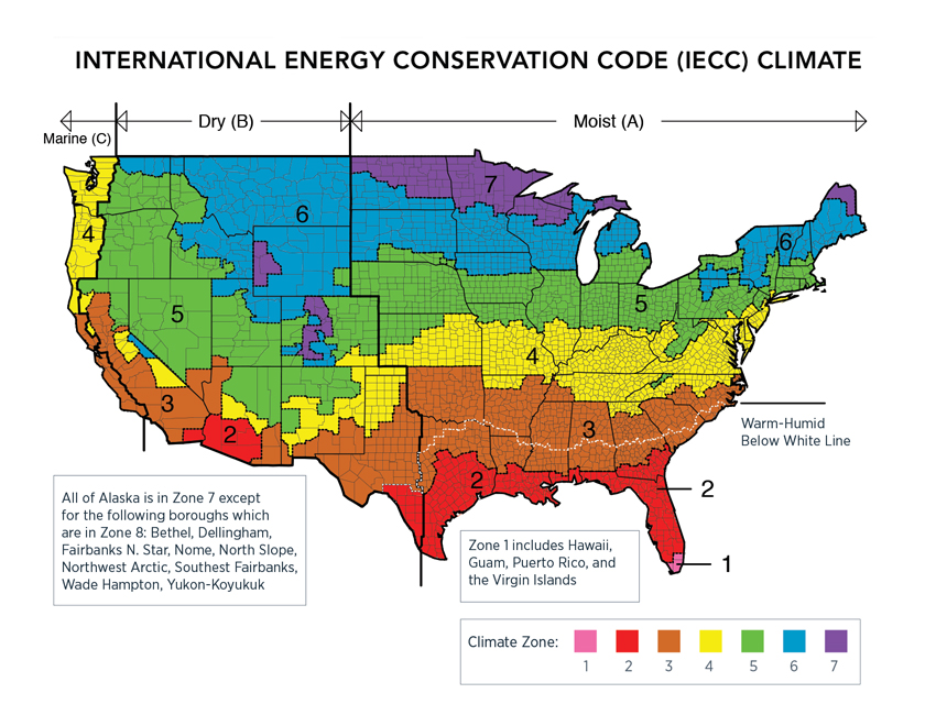
Source: U.S. Department of Energy
The International Energy Conservation Code has established eight climate zones across the country based on heating and cooling needs as well as humidity conditions.
- ASHRAE 90.1: The American Society of Heating Refrigeration and Air Conditioning Engineers (ASHRAE) has long been the authority on energy use in mechanical equipment in buildings and has also developed standards related to the building enclosure, including exterior walls. The standard known as ANSI/ASHRAE/IES 90.1: Energy Standard for Buildings Except Low-Rise Residential Buildings has served as a benchmark for energy use in commercial buildings in the United States and around the world. The IECC recognizes this standard as an “equivalent” rather than identical set of criteria to demonstrate energy code compliance in commercial buildings (not applicable to low-rise residential buildings). It is important to note that there are some differences between ASHRAE 90.1 and the IECC, such as mechanical and electrical requirements being somewhat more stringent, but building enclosure requirements are a little more lenient in some cases. However, design teams cannot mix which standard to follow on a single project—either all of the requirements of the IECC must be followed or all of the requirements of ASHRAE 90.1 must be followed.
- Prescriptive vs. Performance: Almost all codes contain both prescriptive and performance options to demonstrate compliance. Prescriptive requirements are based on a printed set of criteria that can be looked up on a table or otherwise be readily identified based on the specific conditions of a building. They tend to follow an “if/then” approach, as in if the building is located in “x” climate zone, then “y” level of wall insulation must be provided. By identifying the conditions specific to a particular building, the appropriate variables can be selected and a determination easily made as to whether it complies with code. By contrast, the performance path takes the approach of identifying the outcome and leaving it to the designer to prove that it has been met. In this case, the individual prescriptive requirements can waived if it can be shown that the overall objective has been met. Under this approach, the insulation levels of walls, floors, roofs, etc. may all vary provided the overall energy use of the building is within code performance limits. Proving this claim usually requires some type of computerized analysis following specific methodologies.
- Prescriptive R-Value Requirements: For building designs that are fairly straightforward, it is common to look at the prescriptive requirements of the energy code. IECC Residential Table R402.1.2 shows the minimum requirements for insulation R-values in all opaque components of the building envelope. The first thing to notice is that there are separate rows for each climate zone. Hence, to determine what the minimum R-value requirements are for insulation, the designer must pick the correct climate zone. The columns of the table then list requirements for roofs, walls, floors, and doors. For wood-framed walls, there are choices of higher levels of cavity insulation (suggesting 2-by-6 construction) or lower levels of cavity insulation, plus a minimum amount of continuous insulation (suggesting 2-by-4 construction). For commercial applications, Table C402.1.3 provides similar comparative information based on climate zones.
- Prescriptive U-Factor Option: Instead of showing compliance purely on the basis of the R-value of the insulation, the code allows calculations of the entire assembly to be performed to demonstrate that it is below the maximum U-factor. In this case, the designer would need to produce calculations similar to our prior examples, either showing all cavity insulation or with the addition of continuous insulation. Note, however, that under this method, there is a dramatic adjustment required when metal studs are used. Table C402.1.4.1 of the IECC identifies correction factors that must be used for the effective R-value of cavity insulation. The correction factors are calculated based on the nominal stud depth (i.e., 3½, 6, or 8 inches), the spacing of the framing (16 or 24 inches on center), and the cavity R-value of the insulation (R-13 to R-25). So, for example, a common exterior wall framed with 6-inch metal studs at 16 inches on center and filled with R-19 insulation between the studs has a correction factor of 0.37 and therefore must use an effective R-value of only R-7.03. This correction factor and dramatic 63-percent reduction in R-value of the insulation accounts for the thermal bridging of the very conductive metal framing members.
Based on all of the above, it should be clear that showing compliance with the IECC requires some attention to detail in terms of building types, climate zones, cavity insulation, continuous insulation, and thermal bridging.
Vapor Retarders and Moisture Management
Beyond thermal performance, there is an additional aspect of providing full exterior continuous insulation, particularly in cold climates. As noted, both the IRC and the IBC recognize that insulated walls need an interior vapor retarder to prevent warm, moist air from entering into the wall assembly, condensing, and causing the potential for damage, rot, mold, or other issues. The code classifies vapor retarders based on perm ratings (the lower the perm rating, the less water vapor that passes through the material) as follows. (See Section 1405.3 of the 2015 IBC or Section 702.7 of the IRC with the same language.)
- Class I vapor retarders have a very low perm rating of less than or equal to 0.1 and include materials such as sheet polyethylene or nonperforated aluminum foil and some plastic foam insulation.
- Class II vapor retarders have a moderate perm rating greater than 0.1 but less than or equal to 1 as found in kraft-paper-faced fiberglass batts or certain vapor retarder tested paints.
- Class III vapor retarders have a higher perm rating of greater than 1 but less than or equal to 10 and is common of most latex or enamel paint.
The Building Codes (IBC, IRC) go on to identify where each class of vapor retarder shall and shall not be used by referring, in part, back to the climate zones of the energy code (IECC). The warmer climate zones 1 and 2 shall not have either class I or II vapor retarders installed on the interior (warm) side of framed walls, while climate zones 3 and 4 may not have class I vapor retarders installed. The rationale for these restrictions is that the average climate conditions in zones where it is often significantly hotter and moister on the outside of a building than on the inside would be such that a low perm rate vapor retarder (class I or class II) could trap unwanted moisture in a wall. For the colder climate zones 5, 6, 7, 8, and marine 4, either class I or class II vapor retarders are required because those average climate conditions are more conducive to having water vapor condense into damaging water droplets inside of a framed wall.
All of the above notwithstanding, a significant code exception exists in regard to the use of class I and II vapor retarders in the colder climate zones 5, 6, 7, 8, and marine 4. The presence of plastic foam continuous insulation outside of the studs is acknowledged as altering the conditions for interior vapor retarders as long as an adequate amount of such continuous insulation is used. Both the IRC and the IBC identify the amount of continuous insulation needed to achieve this exception. Specifically, Table 1405.3.2 of the IBC or Table 702.7 in the IRC list the specific R-values for continuous insulation broken out by climate zone 5, 6, 7, 8, and marine 4. The amount of CI varies based on the climate zone and whether 2-by-4 or 2-by-6 framing is used. If the wall design meets the stated criteria, then a class III vapor retarder is called for.
Why does the code make this exception? The reason is once again found in the basic physics of what is happening in the wall. Water vapor in the air is a naturally occurring condition that is measured on the basis of relative humidity (RH). The relationship between the air temperature and the amount of RH determines under what conditions that moisture can condense and turn from its gaseous state to the liquid state of water drops. The point where that happens is called the dew point. The construction concern is that if warm, moist air with a high RH seeps into a cool exterior wall cavity, the dew point might be reached within the wall, causing water droplets to form and accumulate inside the wall. That water could contribute to the growth of mold under warm conditions or could freeze and cause other problems if the wall temperature continues to cool down. This balance between continuous insulation and dew point is the reason that the building codes provide the exception for class I and II vapor retarders in the colder climate zones.
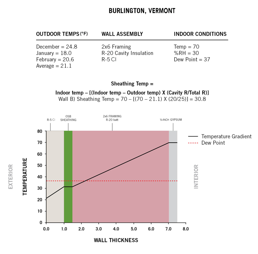
To illustrate this, let’s take an example in climate zone 6 of Burlington, Vermont, where the average outdoor winter temperature is 21.1 degrees Fahrenheit.
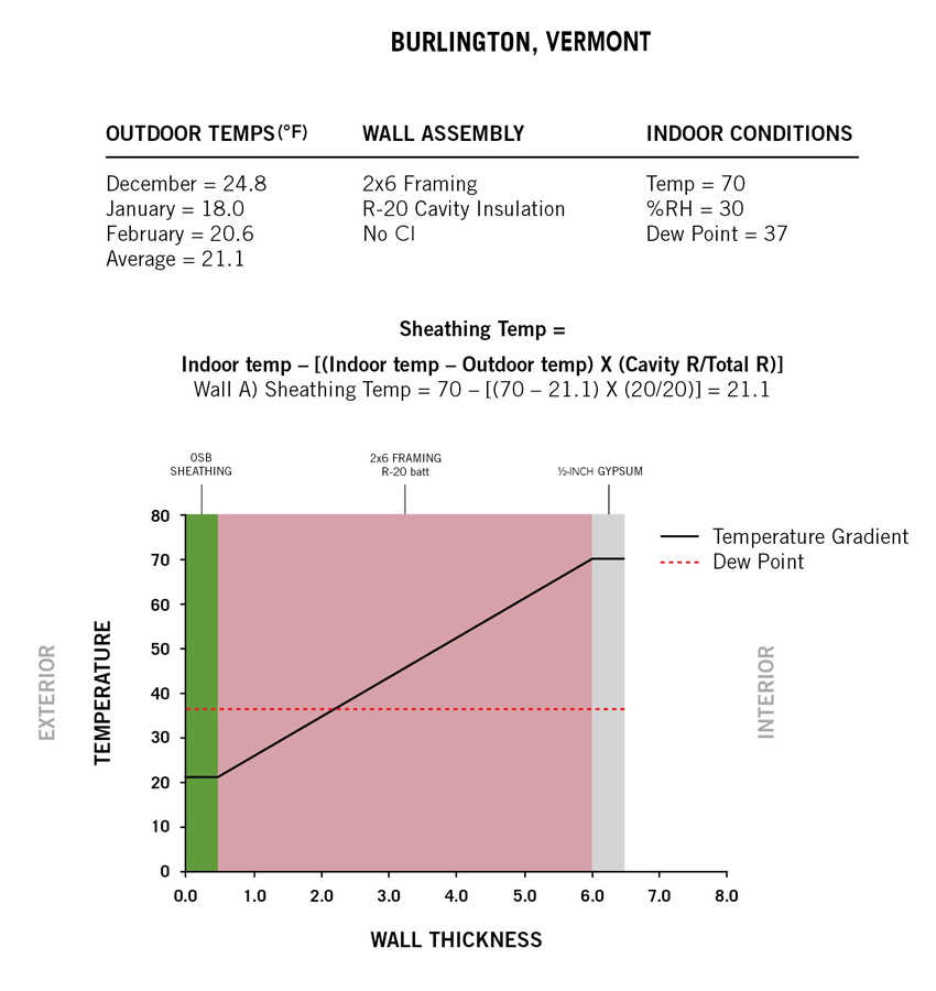
In this example showing wall construction in climate zone 6 with only cavity insulation, the temperature of the exterior sheathing is equal to the outdoor temperature and below the dew point during winter months.
Average indoor conditions can be assumed at 70 degrees Fahrenheit with 30 percent relative humidity. Under this scenario, the dew point is calculated to occur at 37 degrees Fahrenheit. The question becomes, where in the wall assembly would we expect the temperature to be at 37 degrees Fahrenheit when the interior surface is at 70 and the exterior is at 21.1 degrees Fahrenheit? The answer will depend on the rate of heat transfer in the wall, meaning it will depend on the amount of insulation used and its location. In a 2-by-6 wood-framed wall with R-20, permeable cavity insulation, and no continuous insulation, the 37-degree-Fahrenheit dew point can be calculated to occur within the cavity insulation. Water will need a surface to condense on so that means the inner face of the exterior sheathing becomes important. We can calculate the surface temperature of that sheathing based on the insulation location and see that, in this case, it will basically be the same as the outdoor temperature of 21.1 degrees Fahrenheit and well below the dew point, allowing condensation and ice to form between the insulation and inside face of the exterior sheathing—hence the need for protection with a class I or II vapor retarder.
By contrast, let’s look at what happens when we add continuous insulation to this wall assembly. If we take all of the same conditions but this time add R-5, low-permeability continuous insulation, we see that we can raise the surface temperature of the sheathing to just under 31 degrees Fahrenheit—a distinct improvement but still below the dew point of 37 degrees Fahrenheit.
In this example showing R-5 continuous insulation, the sheathing temperature is warmer than the outside condition but still below the dew point during winter.
In order to get the sheathing temperature above that mark, we would need to increase the continuous insulation to R-11.25, which would result in a sheathing temperature of 38.7 degrees Fahrenheit or above the dew point.
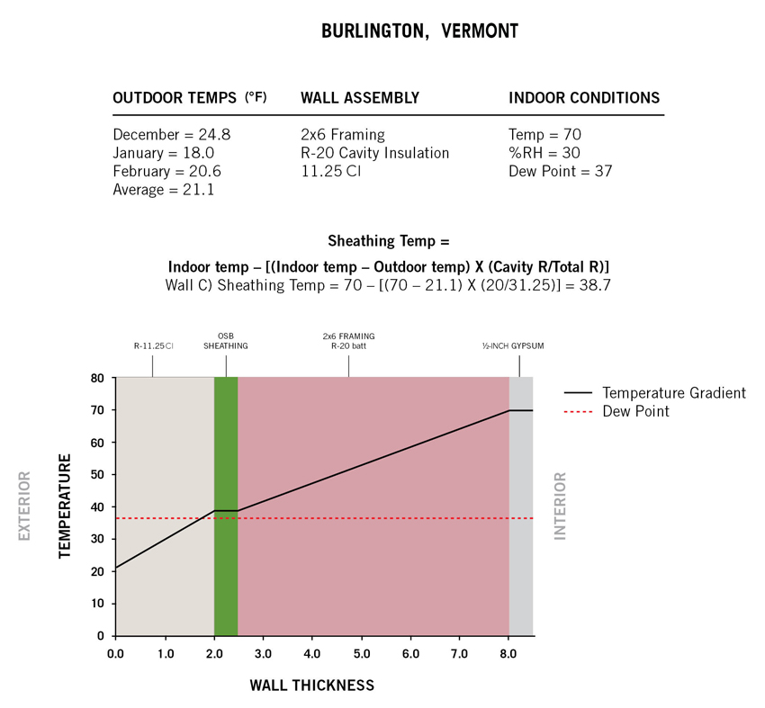
In this example, increasing the continuous insulation to R-11.25 raises the temperature of the sheathing to be above the dew point, meaning that only a class III interior vapor retarder is required or allowed.
If we look back at Table 1405.3.2 of the IBC or Table 702.7 in the IRC discussed above, we find that the amount of continuous insulation required in climate zone 6 is indeed R-11.25 allowing use of a class III vapor retarder instead of the otherwise required class I or II.
Based on all of the above, it should now be more apparent why section 1405.3.2 states, “Only class III vapor retarders shall be used on the interior side of frame walls where foam plastic insulating sheathing with a perm rating of less than 0.1 is applied…on the exterior side of the frame wall.” In essence, this language is concurring with the science that shows that there is no need, in fact there might be harm, in using a higher-rated class I or class II vapor retarder in walls that have continuous foam insulation. Since most of the foam insulation used for continuous insulation meets the 0.1 perm rate criteria (i.e., class I), the addition of a comparably low interior vapor retarder would run the risk of trapping any moisture between these two surfaces. The moisture management strategy of a wall assembly in this case is to use a higher perm rated class III retarder on the inside, thus allowing for drying toward the interior side of the building.
How Much Continuous Insulation to Use?
In any given project, the question of how much continuous insulation to use will likely need to be addressed. Determining the minimum code requirements for continuous insulation begins with identifying where to start based on the variables we have discussed in this course. First, the particular building or project needs to be confirmed as either residential or commercial under the IECC, not just under the IBC and IRC. Second, the county where the project is located needs to be confirmed so the appropriately assigned climate zone can be identified. Third, the determination has to be made whether the IECC or ASHRAE 90.1 will be followed as the means to show energy code compliance since they will have slightly different minimums in some cases. Fourth, the choice needs to be made whether the design will meet or exceed all of the specific prescriptive requirements or if compliance needs to be proven using a computerized analysis. Once those four basic determinations are made, the rest will follow from there.
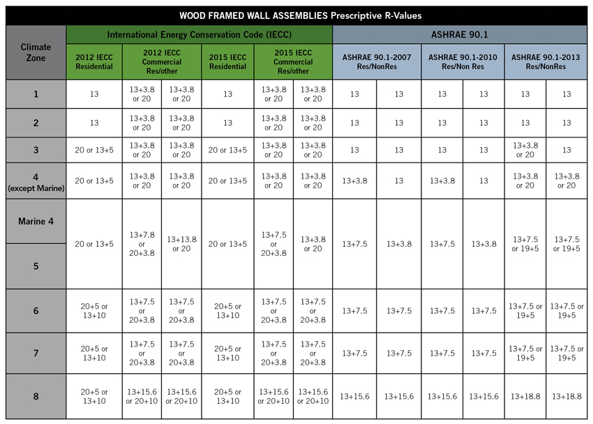
The chart above summarizes the prescriptive R-values for insulation under different versions of the various codes that could be applicable to wood-framed walls. Where two values are shown, the first refers to minimum R-values for cavity insulation and the second refers to minimum R-values for continuous insulation.
Illustrative Examples
To illustrate how this plays out, let’s assume an example project that is a three-story, wood-framed, multifamily building that qualifies as residential under the IECC definition. Further, let’s assume a location in climate zone 5, that the IECC will be followed, and that the goal is to simply meet the prescriptive requirements listed in the code. In this case, we would look to Table R402.1.2 in the residential portion of the IECC to see the criteria that need to be met. There, we would learn that for a wood-framed wall in climate zone 5, we have a choice. This table says we can provide either R-20 insulation in the stud cavities (2-by-6) or we can reduce the cavity insulation to R-13 (2-by-4) if we provide an additional layer of R-5 continuous insulation (R-18 total). In the interest of addressing vapor retarders, we would also look at Table 702.7 of the IRC to see whether a class III vapor retarder is acceptable. Here, we would find that either minimum R-5 CI would need to be provided over a 2-by-4 framed wall or minimum R-7.5 CI would be needed over a 2-by-6 framed wall to allow the use of a class III vapor retarder. In this case, if the 2-by-4 wall with R-13 cavity insulation plus R-5 CI foam were used to meet the thermal insulation requirements, then it would also meet the requirements to drop to a class III vapor retarder. The 2-by-6 wall with only R-20 cavity insulation would still require a class I or II vapor retarder.
Now, let’s consider some variations on this example and see what changes in code requirements. Suppose the owner asks to enlarge the project and raise it up to four stories. It no longer qualifies under the residential portion of the IECC and flips over to the commercial portion. However, as a multifamily building it is still a group R occupancy as defined by the IBC. Hence, we turn to table C402.1.3 and discover that we also have choices there. This table differentiates between group R occupancies and all other occupancies. In some cases, the wall insulation requirements are the same, as in climate zone 4, but since we are in climate zone 5, we discover that the group R requirements are a bit higher than all others. The table shows that we can either provide R-13 insulation in the stud cavities plus R-7.5 CI (2-by-4 framing – R-20.5 total) or provide R-20 plus R-3.8 CI (2-by-6 framing – R-23.8 total), a somewhat more stringent option compared to the R-18 total in the residential portion. If this were a nonresidential use in a different occupancy group, then the requirements would be a bit less stringent at R-13 cavity insulation plus R-3.8 CI (2-by-4 framing – R-16.8 total) or R-20 cavity insulation (2-by-6 framing). Of course, there may be reasons to go beyond the code minimum and still provide a higher level of insulation, but this does illustrate some of the differences between the residential and commercial portions for thermal performance requirements.
As far as vapor retarders and dew points go, however, it doesn’t matter whether the building is residential or commercial. Table 1405.3.2 in the IBC lists the same requirements as Table 702.7 of the IRC for switching from a class I or II to a class III vapor retarder in climate zone 5, namely R-5 CI over 2-by-4 framed walls or R-7.5 CI over 2-by-6 framed walls. In this case, a 2-by-4 wall that meets the thermal requirements of R-13 plus R-7.5 CI will also meet the R-5 requirement for a class III vapor retarder. However, a 2-by-6 framed wall will also need R-7.5 CI to meet the vapor retarder threshold, not just the R-3.8 CI called for to meet thermal requirements only. Hence, it is important to look at both thermal requirements and class III vapor retarder provisions of the codes to determine if there are any differences between the two.
As another variation, let’s assume the three-story building is a prototype that the architect is subsequently hired to modify to suit another location in another state—and a different climate zone. The basic decisions need to be repeated to confirm what does and doesn’t still apply. In this case, it would be residential under the IECC and still be seeking to follow the IECC prescriptive approach, but we discover the building now has to meet the requirements of climate zone 6 instead of climate zone 5. We thus go back to R402.1.2 and find that the wall construction still provides a choice, but the requirements are notably higher. We can still use either R-13 or R-20 insulation in the stud cavities (depending on 2-by-4 or 2-by-6 framing), but continuous insulation is no longer optional since it is required in both cases: R-5 CI minimum with R-20 walls (R-25 total) or R-10 CI minimum with R-13 walls (R-23 total). Clearly, the building location in terms of the climate zone makes a significant difference on the minimum R-values for the insulation.
To determine the choice of vapor retarder in this case, we return to Table 702.7 of the IRC, this time looking at the thresholds for climate zone 6, namely R-7.5 CI over 2-by-4 framed walls or R-11.25 CI over 2-by-6 framed walls. Again, in this case, a 2-by-4 wall that meets the thermal requirements of R-13, plus R-10 CI will also meet the R-7.5 requirement for dropping to a class III vapor retarder. However, a 2-by-6 framed wall will need R-11.25 CI to meet the vapor retarder threshold, not just the R-5 CI called for to meet thermal requirements only. Hence, climate zone continues to influence minimum insulation decisions both in terms of thermal requirements and the use of class III vapor retarders.
Creative Alternatives
As a final variation, let’s assume the design team has come up with a slightly creative approach to the wall assembly that doesn’t exactly meet the prescriptive criteria of the R-value tables. The IECC does have another prescriptive alternative in the form of U-factor tables. This allows the design team to present its calculations for a wall assembly based on achieving an overall U-factor for the assembly. The weighted determinations need to be shown for framing and insulated portions of the walls as in our earlier examples. Since the code does not seek to dictate design or discourage innovation, it naturally allows the same process to be used for any wall construction designs and states the overall U-factor maximums as the prescriptive requirements. In our residential, climate zone 5 example, the maximum overall U-factor that needs to be demonstrated is U-0.06 (equal to R-16.6 overall) per table R402.1.4. It might sound like this is less stringent than the R values we saw earlier, but actually it is not. Keep in mind that in the R-value table, only the insulation is prescribed—it conservatively assumes the rest of the assembly, and if the U-factor calculations were performed for this “assumed” assembly, it would similarly work out to about U=0.06. Therefore, an innovative or alternative wall assembly using the prescriptive U-factor approach would need to achieve a “whole assembly” U-factor of 0.06 or less to be considered compliant. This same process would be applicable if following the commercial portion using Table C402.1.4 with the resulting maximum allowable overall U-factor at a slightly more lenient U-0.064 (equivalent R-15.6).
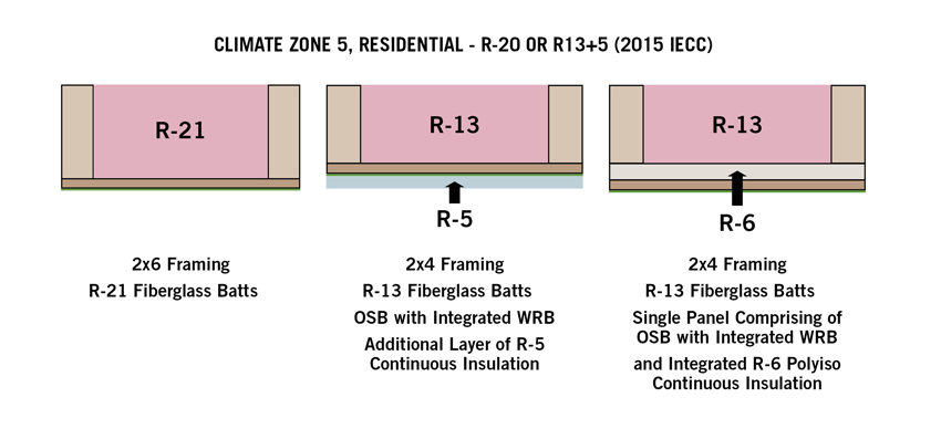
These wall sections are examples of various ways to meet the prescriptive insulation requirements of the IECC under Table R402.1.2.
Keep in mind that the code is, of course, a minimum requirement. There can be many reasons to exceed this minimum threshold, whether to meet higher standards of voluntary programs such as LEED or simply to boost the overall energy performance of the building as a best practice for building owners. There may also be some practical reasons, too. The IECC examples above refer repeatedly to R-5 and R-3.8 continuous insulation, but if polyiso insulation is used, it would be more prudent to round up to the nearest standard thickness, such as R-6 (1 inch thick) or R-4.5 (3/4-inch thick). Standard offerings will typically be more cost effective than customized ones and, in this case, offer a bit of a safety factor for thermal performance.
Conclusion
Continuous insulation has become part of the mainstream of framed wall construction. Codes and green building standards recognize the significance of it and even require it in many climate zones around the United States. The technologies for providing it have evolved in the past decade or so to allow it to be integrated readily into common construction techniques. There are even combined sheathing products that offer continuous insulation adhered to one side to reduce labor time. Products like these can also influence a reduction in the type of vapor retarder required in a wall assembly. The result is a high-performance, cost-effective, durable, and easier-to-install wall assembly solution.
End Notes
1ICC Evaluation Service Report ESR-3373. June 2015. Web. 12 October 2016. www.huberwood.com/assets/user/library/ESR-3373_(Comb._06-2016).pdf.
Peter J. Arsenault, FAIA, NCARB, LEED AP, is a practicing architect, green building consultant, continuing education presenter, and prolific author engaged nationwide in advancing building performance through design. www.linkedin.com/in/pjaarch

|
ZIP System® building enclosures offer structural and sealing products for a quick rough dry-in. A revolutionary alternative to traditional
sheathing and building wrap, ZIP System™ sheathing and tape create a streamlined roof and wall sheathing system with integrated weather
and rigid air barriers. The simplified approach to structural roofs and walls helps building teams save time by eliminating installation steps
and achieving a quick rough dry-in to accelerate interior work. Backed by a 180-Day Exposure Guarantee and 30-Year Limited Warranty,
ZIP System building enclosures not only help keep jobs on track but also provide reliable exterior water management during and after
construction.
Learn more at InsulateYourBuild.com.
|