This CE Center article is no longer eligible for receiving credits.
Image courtesy of GAF
Wind design of roof systems is one of the more complicated things that an architect deals with during the design of a building. And with the latest version of ASCE 7, “Minimum Design Loads For Buildings and Other Structures” (ASCE 7), it has become that much more challenging for roof system designers, roof system manufacturers and roofing contractors. Different editions of building codes exist, and therefore, different versions of ASCE 7 are being used in different parts of the country. The three versions that are currently in use are ASCE 7-05, 7-10 and 7-16, with the last two digits representing the year of publication (e.g., “-05” indicates 2005).
The progression of ASCE 7 during the last two decades had added complexity to what was once a relatively straight-forward calculation. Understanding the similarities and differences between the three versions of ASCE 7 provides for better recognition of the current version’s complexity and allows for more appropriate wind load determination.
Roof systems that have the tested capacity to resist calculated design wind pressures can be found in approval listings (e.g., UL, FM). Recognizing how a safety factor is included in the approval listing is critical to ensuring an appropriate roof system is selected and installed. Conceptually, the goal is to determine the design wind loads, then select the appropriate roof system with a tested resistance greater than the design wind loads. If it were only that simple! Yet while it certainly can be complicated, there are ways to break down the steps of wind design in order to make it much more digestible for architects and specifiers.
This course will discuss and analyze the process for determining wind design pressures and selecting an appropriate roof system from a more-conceptual, what-does-the-book-say approach and, additionally, will provide in-depth analysis for case studies in two cities.
Building Code Requirements
Before we get into a discussion about the wind design process, it’s appropriate to discuss the requirements in the building code. The 2018 IBC (as well as prior versions) has very specific requirements for what is to be included on the construction documents regarding wind design of roof systems.
The 2018 IBC, in Section 1603, Construction Documents, states:
“1603.1 General. Construction documents shall show the size, section and relative locations of structural members with floor levels, column centers and offsets dimensioned. The design loads and other information pertinent to the structural design required by Sections 1603.1.1 through 1603.1.9 shall be indicated on the construction documents.
Exception: Construction documents for buildings constructed in accordance with the conventional light-frame construction provisions of Section 2308 shall indicate the following structural design information:
- Floor and roof dead and live loads.
- Ground snow load, Pg.
- Basic design wind speed, V, miles per hour (mph) (km/hr) and allowable stress design wind speed, Vasd, as determined in accordance with Section 1609.3.1 and wind exposure. (Emphasis added.)
- Seismic design category and site class.
- Flood design data, if located in flood hazard areas established in Section 1612.3.
- Design load-bearing values of soils.
- Rain load data.”
The 2018 IBC further states, in Section 1603.1.4, Wind design data that the following is to be included on construction documents.
“1603.1.4 Wind design data. The following information related to wind loads shall be shown, regardless of whether wind loads govern the design of the lateral force-resisting system of the structure:
- Basic design wind speed, V, miles per hour and allowable stress design wind speed, Vasd, as determined in accordance with Section 1609.3.1.
- Risk category.
- Wind exposure. Applicable wind direction if more than one wind exposure is utilized.
- Applicable internal pressure coefficient.
- Design wind pressures to be used for exterior components and cladding materials not specifically designed by the registered design professional responsible for the design of the structure, psf (kN/m2).”
In the end, the design architect’s responsibility is to provide the necessary design wind loads; the manufacturer is responsible for testing roof systems in order to determine wind uplift capacity; and the roofing contractor is responsible for proper installation that follows the construction documents, project specification, and installation instructions.
Wind Loads and Metal Edge Systems. In addition to the requirements for wind design of the roof system itself, the 2018 IBC has specific requirements for edge securement for low-slope roofs. The code language in Section 1504.5, Edge securement for low-slope roofs, states that a roof’s metal edge securement is to be designed and installed in accordance with Chapter 16, Structural Design, and tested to determine its resistance (i.e., wind-resistance capacity). The code language specifically states that metal edge systems are to be tested according to ANSI/SPRI ES-1, Test Standard for Edge Systems Used with Low Slope Roofing Systems.
Why is this a concern? Because it is widely acknowledged within the roof industry that many roof system failures during high wind events initiate at the perimeter edges, the edge securement of the roof is critical to long-term wind-uplift performance. Codification of edge metal securement is the result of years of analysis and inspection of roof system failures after high wind events. Common edge systems for roofs include L-shaped metal, gravel-stop metal and copings used on the top of parapet walls.
ES-1 Specifics. Edge systems for membrane terminations are divided into two separate, large-bucket categories—dependently and independently terminated systems. Dependently terminated systems are used with ballasted roofs, roofs that are adhered with ribbons or spots of adhesives, and mechanically attached roofs where the roof membrane’s attachment locations are greater than 12 inches from the roof edge. Independently terminated systems are used with fully adhered roof membranes and mechanically attached roofs where the attachment locations are 12 inches or less from the roof edge. The latter are considered to have ‘peel’ stops within one foot of the roof edge.
ES-1 includes three test methods (RE-1, RE-2 and RE-3), and each is specific to a type of edge metal and membrane-attachment system. The RE-1 test method determines a metal edge’s ability (i.e., capacity) to restrain the roof membrane (dependently terminated) from the forces created by wind pressures for ballasted roofs and the types of intermittently attached membranes described above. The RE-2 test method determines a metal edge’s capacity to resist outward, horizontal pressures that occur during high winds. RE-2 is used for both dependently and independently terminated roof membranes. The RE-3 test method determines the capacity of a metal coping when both upward and outward loads are applied.
Determining the Loads Acting on a Rooftop
Simply put, a roof assembly must be able to resist the design wind loads acting on the rooftop. The loads acting on a roof must be calculated in order to select a roof system that has the necessary capacity (i.e., wind uplift resistance). Therefore, step one is to determine the loads acting on the roof of a specific building.
There are a number of factors that determine the design wind uplift loads for the field, perimeter and corners of a roof. In order to determine the wind loads acting on a roof, the architect/designer needs to know the following about a building—location; building code that is in effect at the building’s location; height, length and width; exposure category; use and occupancy; enclosure classification; topographic effects; and ground elevation.
Location. The location of the building within the United States tells us two things which must be determined in specific order. The location directs us to the specific version of the IBC or the applicable building code that is in effect for the project. For example, if the 2006 or 2009 IBC is in effect, then ASCE 7-05 governs. If the 2012 or 2015 IBC is in effect, then ASCE 7-10 governs. If the 2018 IBC is in effect, then ASCE 7-16 governs.
Height, Length, Width. Determining the height, length and width of a building should be straightforward and a vast majority of buildings are predominately square or rectangular in shape, or in general, have square or rectangular roof areas. Note: there are methods to determine the wind loads acting on a roof for non-rectangular or non-square buildings; however, that is outside the scope of this article.
Exposure Category. Exposure category is based on the roughness of a building’s nearby terrain. A terrain’s surface roughness is determined from natural topography, vegetation and the surrounding construction.
ASCE 7 uses three Surface Roughness Category types—called B, C and D—which in turn, defines three Exposure Category types, also called B, C and D.
Exposure Categories B, C and D are generally defined as follows:
- Exposure B is applicable to buildings with a mean roof height of less than or equal to 30 feet and where surface roughness B prevails in the upwind direction for a distance greater than 1,500 feet tor buildings with a mean roof height greater than 30 feet, Exposure B shall apply where surface roughness B prevails in the upwind direction for a distance greater than 2,600 feet or 20 times the height of the building, whichever is greater.
- Exposure C is applicable for all cases where Exposure B and D do not apply.
- Exposure D is applicable where surface roughness D prevails in the upwind direction for a distance greater than 5,000 feet or 20 times the building height, whichever is greater. Exposure D also applies where the ground surface roughness immediately upwind of the site is B or C, and the site is within a distance of 600 feet or 20 times the building height, whichever is greater, from an Exposure D condition.
Use and Occupancy. The use and occupancy of a building is used to determine the “Occupancy Category” in ASCE 7-05 or “Risk Category” in ASCE 7-10 and ASCE 7-16. They are effectively interchangeable terms, however, they are addressed differently. ASCE 7-05 uses Occupancy Category to determine the value to use for the Importance Factor. In ASCE 7-05, Importance Factor is a stand-alone factor in the velocity pressure calculations, and why there is one map in ASCE 7-05. ASCE 7-10 and 7-16 incorporates Risk Category (i.e., importance factor) into the wind speed maps, and that is why there are 3 maps in ASCE 7-10, and 4 maps in ASCE 7-16. In general, the greater the importance of a building, the higher the Importance Factor or Risk Category which results in higher uplift pressures.
Exposure Classification. This factor essentially relates to the possibility that a building will become internally pressurized during a wind event. For ASCE 7-05 and ASCE 7-10, there are three classification types: Open, Partially Enclosed, and Enclosed. ASCE 7-16 amended these classification types by adding another type called, “Partially Open” and also revised some of the definitions. The ASCE 7-16 classification types are Open buildings, Partially Open, Partially Enclosed and Enclosed buildings.
Using “Partially Enclosed” as the building type results in an increase in the design wind pressures in the field of the roof versus an “Enclosed” or “Partially Open” building—all other factors held equal. This is significant. Selecting an “Enclosed” or “Partially Open” building when it could become a “Partially Enclosed” building if doors and windows are blown out during a high wind event could result in a roof system without the adequate capacity to handle the anticipated higher loads.
Topographic Effects. Research and experience has shown that wind speeds can increase significantly due to topographic effects. The wind speed increase is known as a wind speed-up effect. An abrupt change in the topography, such as escarpments, hills or valleys can significantly affect wind speed. ASCE 7 addresses these speed-up effects by applying a multiplier to account for topography in the velocity pressure calculations.
For more in-depth information about determining wind loads, read this blog.
An architect/designer needs to know a building’s location; the building code that is in effect at the building’s location; its height, length, and width; the exposure category; the use and occupancy category; the enclosure classification; any topographic effects; and ground elevation in order to determine the wind loads acting on a roof. Some of these selections may seem straight forward, but some impart a higher resultant design wind load, especially when compounded by similar risk-averse choices. For more information about resilient roof systems, read this blog.
The process of determining the loads acting on a rooftop results in design wind pressures for each roof zone and, importantly, determines the dimensions and overall size of each of the roof zones. Providing this information on the construction documents ensures the contractor and manufacturer (together or separately) can provide an appropriate roof system with the tested capacity that exceeds the design wind pressures in each of the roof zones.
Revisions to ASCE 7-16
Eventually, we will all use ASCE 7-16 as the basis for determining design wind loads for our roofs. To that end, we will need to understand what has remained the same, what is changed, and what has been added to the latest version of ASCE 7.
Basic differences between versions of ASCE. There are some noteworthy differences between the three ASCE 7 editions and they include: the wind speed maps, roof zones, enclosure classifications and external pressure coefficients.
Wind speed maps. Simply put, for the contiguous U.S., ASCE 7-05 has one wind speed map and it is based on the Allowable Stress Design (ASD) method. ASCE 7-10 has three wind maps, based on Risk Category I, Risk Category II, and Risk Categories III and IV, and they are based on the Strength Design method. ASCE 7-16 has four wind speed maps, one for each Risk Category and they are also based on the Strength Design method.
The two design methods used in ASCE-7 are mentioned intentionally. Components and cladding for buildings—which includes roof systems—are allowed to be designed using the Allowable Stress Design (ASD) method. When ASCE 7 changed from the ASD method and went to the Strength Design (a.k.a., Ultimate) method in the 2010 version, it was still appropriate to design roof systems according to the ASD method, but it wasn’t specifically stated as such. Currently, in the 2016 version, ASCE specifically states that components and cladding (i.e., roofs) can be designed using the ASD method. The 2018 International Building Code also provides similar language allowing the use of the ASD method when determining design wind pressures for roof systems. This is important because using the ASD method reduces design wind pressures by forty percent.
Roof Zones. ASCE 7-05 and ASCE 7-10 have three roof zones: field, perimeter and corner. See Figure 1. The dimensions of the zones are mostly determined by a building’s length and width. ASCE 7-16 added another zone and it presents the potential to have four roof zones: interior, field, perimeter and corner. ASCE 7-16 also revised how the dimensions of the zones are sized; it is now based solely on a building’s height. Depending on the proportions of a building, roof zones 1 Prime and 1 may not exist using ASCE 7-17. This possibility is shown in the case studies later in this article.
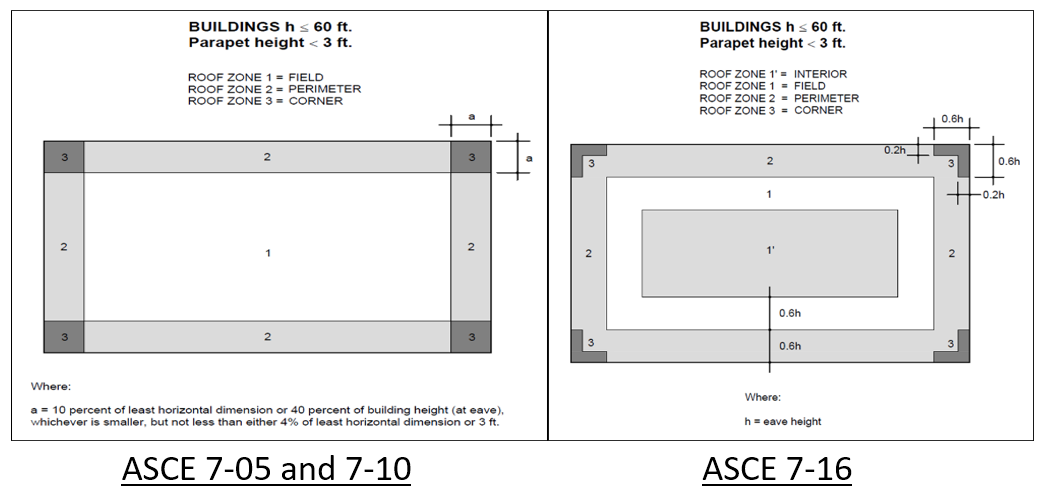
Figure 1: Roof zone layout for ASCE 7-05 and ASCE 7-10.
Enclosure Classifications. As covered previously, ASCE 7-05 and ASCE 7-10 have three classification types: Open, Partially Enclosed and Enclosed, while ASCE 7-16 added Partially Open and slightly modified the definitions. These classifications determine the values to use for the Internal Pressure Coefficient, GCpi. These are shown in Figure 2.
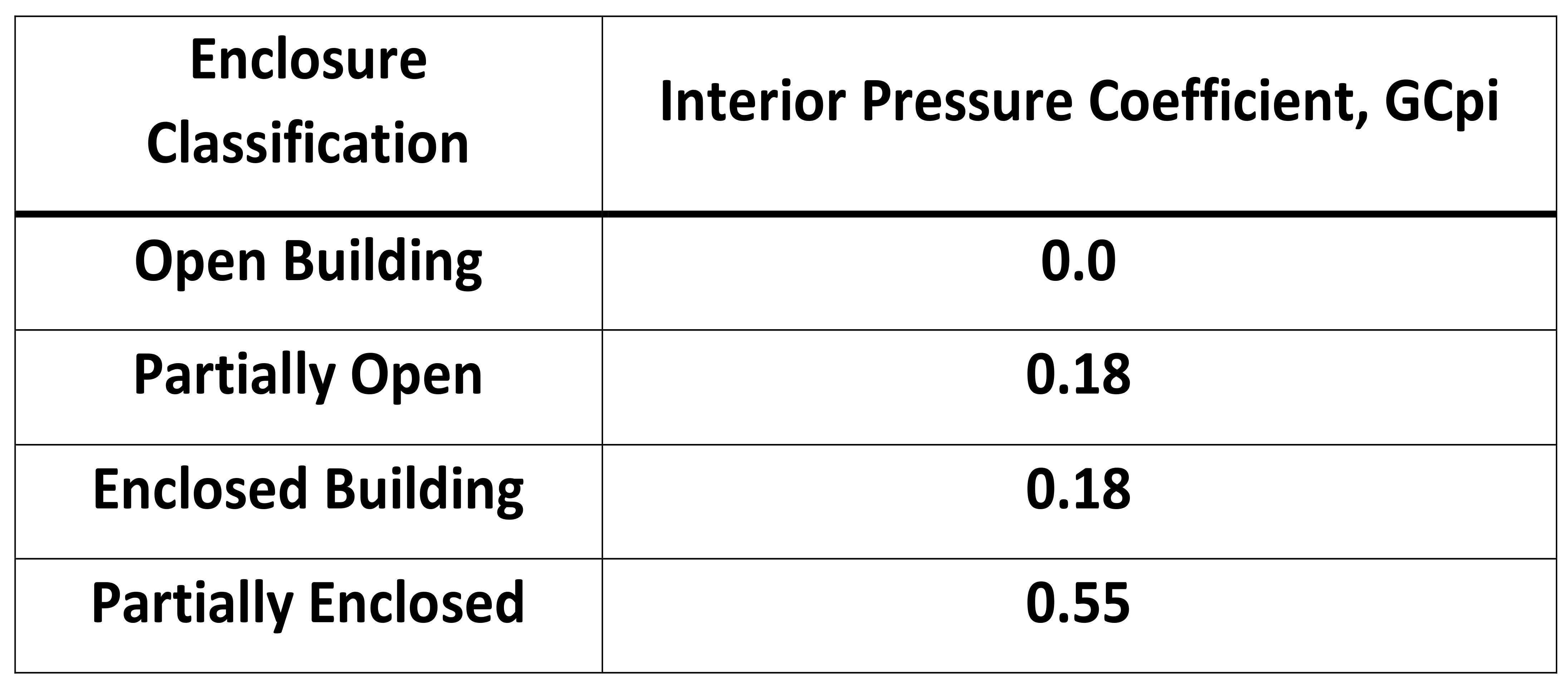
Figure 2: Interior Pressure Coefficients, GCpi, for ASCE 7-16.
. The values for External Pressure Coefficients have been significantly increased in ASCE 7-16. This is where much of the concern with ASCE 7-16 lies—the increase in the External Pressure Coefficients—and how the increases will affect design wind pressures. As seen in
Figure 3, the GCp values for Field of the roof increased by 70 percent, for the Perimeter by 28 percent, and for the Corners by 14 percent. Because of the different configurations of the roof zones and other factors that are intended to allow for a correction (i.e., a reduction) in velocity pressure, it is hard to state—broadly—a percentage that loads may increase. However, the factors selected by a conservative owner (e.g., choosing Partially Enclosed versus Enclosed) also have an effect on the design wind loads. Each project is different, so results will vary. The good news is that the roofing industry has numerous roof assemblies that have tested capacity to meet the design wind loads established under the direction of ASCE 7-16.

Figure 3: External Pressure Coefficients, GCp, for ASCE 7-16.
Determining Velocity Pressure. All of the previously discussed assumptions and selections and characterizations of the building are used to determine the Velocity Pressure for a roof project. The Velocity Pressure is the ‘foundational’ load that is used to determine the design wind pressures for each zone of a rooftop. It’s important to recognize there are two basic steps used to determine design wind pressures acting on a roof. The first step is to determine velocity pressure; the second step is to use velocity pressure to determine design wind loads for roof zones (e.g., field, perimeters and corners).
The equation to determine velocity pressure varies slightly in ASCE 7-05, ASCE 7-10 and ASCE 7-16. ASCE 7 uses the following base equation to determine velocity pressure (qh):
qh = 0.00256 (Kz)(Kzt) (Kd) (V2)(I)
Where:
qh = velocity pressure at mean roof height
Kz = exposure coefficient based on exposure and height
Kzt = topography factor (likely 1.0)
Kd = wind directionality factor (Components and Cladding uses 0.85)
V = basic wind speed for the location
I = Importance Factor (based on Occupancy Category)
Each version of ASCE 7 uses a variation of the above equation. In ASCE 7-05 for example, I—the Importance Factor—is in ASCE 7-05 only. The Importance Factor was absorbed into the wind maps, which means for ASCE 7-10 and ASCE 7-16, the Velocity, V, is adjusted within the wind speed maps. Also new in ASCE 7-16, a ground elevation factor (Ke) can be used to reduce pressures at higher elevations, or it can more conservatively be set to 1.0.
Determining Design Uplift Pressures
This is the second step in determining design wind pressures. After determining the velocity pressures, the next step is to calculate the design uplift pressures specific to the interior (if applicable), field, perimeter, and corner zones of a roof. Design uplift pressures are adjusted by multiplying the velocity pressure (qh) by the appropriate external pressure coefficients (e.g., GCp), as shown in Figure 3. The external pressure coefficient values are based on roof zones and the appropriate “effective wind area” (which we won’t go into in this article). Effective wind area is the tributary area for the element being considered, and 10 square feet is typically used for roof systems.
The internal pressure coefficient values are based on the building design (i.e., the enclosure classification). See Figure 2.
Determining Wind Uplift Resistance
The primary method for determining a roof system’s wind uplift resistance (aka, capacity) is through physical testing. The test methods to determine wind resistance are listed in the IBC Section 1504, Performance Requirements.
In the 2003 and 2006 International Building Code (IBC), for wind resistance of non-ballasted roofs, the codes state that built-up, modified bitumen, adhered or mechanically attached single-ply, through fastened metal panel roof systems, and other types of membrane roof coverings shall be tested in accordance with FM 4450, FM 4470, UL 580 or UL 1897.
In the 2009, 2012, 2015 and 2018 versions of the IBC, for wind resistance of non-ballasted roofs, the codes state that built-up, modified bitumen, adhered or mechanically attached single-ply roof systems, metal panel roof systems applied to a solid or closely fitted deck and other types of membrane roof coverings shall be tested in accordance with FM 4474, UL 580 or UL 1897.
These tests are run by approved testing agencies. FM Approvals, Underwriters Laboratory, Intertek, NEMO, PRI, and others can perform testing—according to the code-approved test methods—that can be used to determine a roof system’s capacity.
It is important that the testing method used to determine the wind-uplift capacity of a roof system is listed in the applicable building code.
Approval Listings. The tested roof systems are found in approval listings. Approval listings are maintained by various entities, such as government agencies, testing laboratories, and even a trade association. Examples of government agencies with approval listings include: Florida Department of Business and Professional Regulation, Miami Dade County, and Texas Department of Insurance. Testing laboratories that have listings of rated roofing assemblies include Underwriters Laboratories and FM Approvals. And lastly, SPRI sponsors the Directory of Roofing Assemblies (DORA) which is an online database of tested assemblies.
Case Studies
The changes to ASCE 7-16 are generally increasing the design wind pressures for roof systems. Increased design wind pressures leads to the use of higher-capacity roof systems. To what extent is this affecting the roofing industry?
Two buildings of different sizes and heights in two cities in the U.S., one centrally located and one along the Gulf coast, were studied to compare design wind pressures based on ASCE 7-10 and ASCE 7-16. By assessing the required roof-system capacity for all roof zones in conjunction with the increases in the size of roof zones, real numbers can be assessed to help answer the question “by how much will ASCE 7-16 affect the low-slope roofing industry?”
Note: While analysis of two building types in two cities does not represent a significant study, this study offers an example of how the 2016 version of ASCE 7 is going to affect installed roofing systems over the next decade.
Case Study Parameters and Design Wind Pressures. Design wind pressures (DWP) were determined for two building types in two cities. DWPs were based on varying the Risk Category and Exposure. Figure 4 shows the building types, cities, variables and constants.
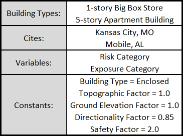
Figure 4: Case study parameters: building type, cities, variable, and constants.
The big box store is 290’ long x 169’ wide x 24’ tall, and the apartment building is 100’ long x 40’ wide x 55’ tall. Wind speeds were determined using ASCE7hazardtool.online, an online tool.
DWPs can be determined by using proprietary third party methods (e.g., RoofNav), simplified calculation tools (e.g., RoofWindDesigner), or hand calculations following the methods within the ASCE 7 standard.
For this case study, DWPs were determined using hand calculations via an Excel spreadsheet. The DWPs are slightly more refined since there was no rounding of wind speeds for ASCE 7-16. Both RoofNav and Roof Wind Designer round to the nearest 5 or 10 mph. The maps in ASCE 7-16 have been revised, not only from a wind speed perspective but from the number of wind isobars on the maps. The ASCE 7-16 maps are more refined which allows for more exact wind speed values.
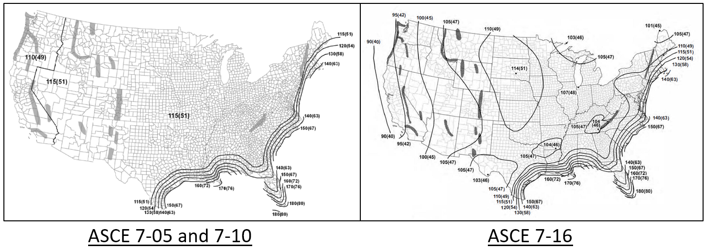
Figure 5: ASCE 7-10 Map, Risk Category II, showing a limited number of wind-speed isobars; ASCE 7-16 Map, Risk Category II, showing many additional wind-speed isobars.
In total, 72 different sets of DWPs were calculated. Buildings over 60 feet tall are designed the same in 7-16 as in 7-10; therefore, this article focuses on buildings less than 60 feet tall.
For this article, the design wind pressure analysis for the big box store in Kansas City, Mo., and the 5-story apartment building in Mobile, Ala., will be presented. The full study can be found here. Figure 6 shows the DWPs for the Big Box store in Kansas City, Mo., and Figure 7 shows the DWPs for the 5-story apartment building in Mobile, Ala.
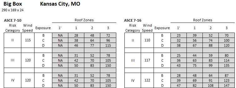
Figure 6: Design wind pressures based on ASCE 7-10 and 7-16 for a big box store in Kansas City, Mo.
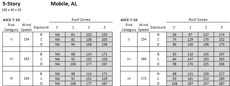
Figure 7: Design wind pressures based on ASCE 7-10 and 7-16 for a 5-story apartment building in Mobile, Ala.
Comparing Percent-Increases in DWP. Using the design wind pressures (for Risk Category III, Exposure C, Enclosed), the percent increase in DWP was calculated for each roof zone for the two case study buildings. The percent increases in DWP were calculated by dividing the ASCE 7-16 value with the corresponding ASCE 7-10 value for each roof zone. However, because there are 4 roof zones in ASCE 7-16 (and 3 roof zones in ASCE 7-10), both Roof Zones 1’ and 1 were divided by the value for ASCE 7-10 Roof Zone 1 to determine the percent increase. Values in the following charts that are below 100 percent (shaded gray) indicate a reduction in DWP from ASCE 7-10 to -7-16. Figure 8 shows the Percent Increases in DWP per Zone for the big box store in Kansas City, Mo., and Figure 9 shows the same for the 5-story apartment building in Mobile, Ala.
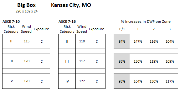
Figure 8: Percent increases in DWP per roof zone for a big box store in Kansas City, Mo.
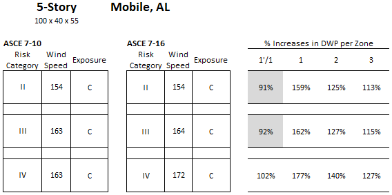
Figure 9: Percent increases in DWP per roof zone for a 5-story apartment building in Mobile, Ala.
For the big box store scenario, the percent increases in DWP per roof zone varies from 84 to 164 percent. The percent reductions (values less than 100 percent) are all in Roof Zone 1’ while Roof Zones 1, 2 and 3 have increased DWP. Roof Zone 1 percent increases are largest, and Roof Zone 3 increases are smallest.
For the 5-story apartment building scenario, the percent increases in DWP per roof zone varies from 91 to 177 percent. The percent increases in Roof Zone 1, again, are the largest while the smallest are in Roof Zone 3. Reductions, again, only occur in Roof Zone 1’.
It is worth noting that the increases in Pressure Coefficients from ASCE 7-10 to 7-16 (Figure 3) are, in fact, relatively indicative of the increases in DWP. For more on Pressure Coefficients and the wind design process, see this blog.
These two case studies show the 2016 version of ASCE 7 imposes higher DWPs in Roof Zones 1, 2 and 3. However, given the substantial reductions in Roof Zone 1’, it could be expected that installed roof system capacity will be lower. While that is hopeful, the roofing industry has a minimum-capacity backstop of 60 psf. This means that any calculated DWP at or below 60.0 psf (even for DWP values as low as 23 psf [Figure 6]) will have a 60-psf-capacity roof assembly installed to meet building code requirements. The reality is many buildings are required to use a 60-psf-capacity roof system when in fact ’60 psf’ is more capacity than needed based on calculated DWPs.
Comparative Analysis of Roof Zones and Uplift Ratings
Analyzing the roof zone layouts and the associated wind-uplift ratings based on the 2010 and 2016 versions of ASCE-7 provides a more direct comparison for each of the two case studies.
Big Box; Kansas City, Mo. The big box store in Kansas City, Mo. saw the DWP increase from 38 psf to 56 psf in Roof Zone 1 per ASCE 7-10 vs ASCE 7-16; and reduce to 32 psf in Roof Zone 1’. Because the lowest available wind-uplift rated roof system is rated to 60psf, the increases or decreases in Roof Zone 1 and 1 Prime are rendered ineffectual. A 60-psf-capacity roof should be installed in both Roof Zone 1 and Roof Zone 1’ per ASCE 7-10 and 7-16. Figures 10 and 11 show the roof zone layouts, associated design wind pressures, and the minimum wind-uplift rating for each roof zone for a big box store in Kansas City, Mo.
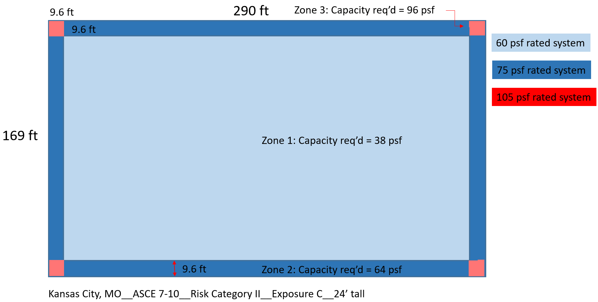
Figure 10: Roof zone layouts, design wind pressures, and the minimum wind-uplift rating for each roof zone for a big box store in Kansas City, Mo. based on ASCE 7-10.
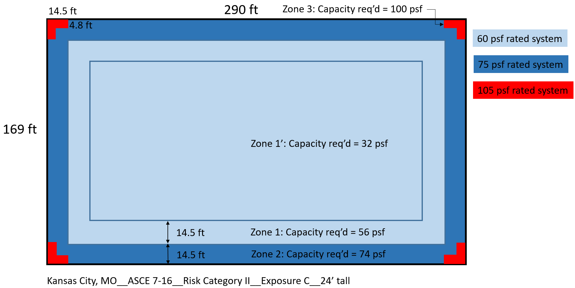
Figure 11: Roof zone layouts, design wind pressures, and the minimum wind-uplift rating for each roof zone for a big box store in Kansas City, Mo. based on ASCE 7-16.
For Roof Zones 2 and 3, the DWPs are not only increased, but the sizes of the roof zones that require higher capacity are also increased. Roof Zone 2 per ASCE 7-10 required a 75-psf-capacity roof, and a 75-psf-capacity roof will be needed per ASCE 7-16.
In this case, because of the increased size of the roof zones (specifically Roof Zone 2), approximately 9 percent of the roof area will need a higher capacity roof. Figure 12 shows roof area percentages based on the required roof system capacity for this scenario.
Big Box Roof Example (Kansas City, MO)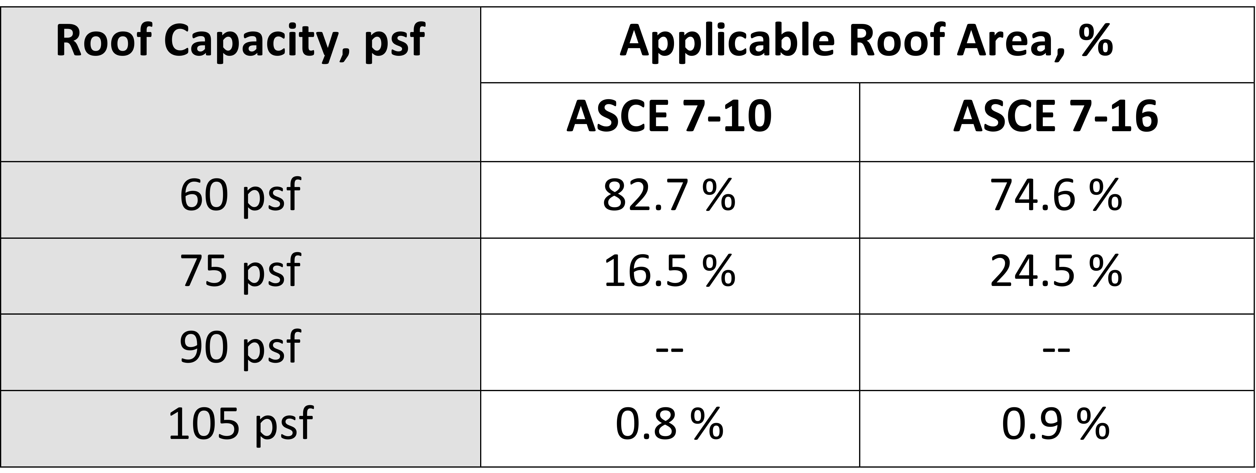
Figure 12: Required roof capacity and the roof area (%) where each is required.
5-story Apartment; Mobile, Ala. The 5-story apartment building in Mobile, AL (Risk Category II, Exposure C) saw the DWP increase from 81 psf to 129 psf in Roof Zone 1 per ASCE 7-10 vs ASCE 7-16; and reduce to 74 psf in Roof Zone 1’. However, and very importantly, because of the way the roof zone sizes are determined using ASCE 7-16, Roof Zones 1’ and 1 do not exist in this scenario. Figure 13 shows the roof zone layouts, associated design wind pressures, and the minimum wind-uplift rating for each roof zone for a 5-story apartment building in Mobile, Ala.
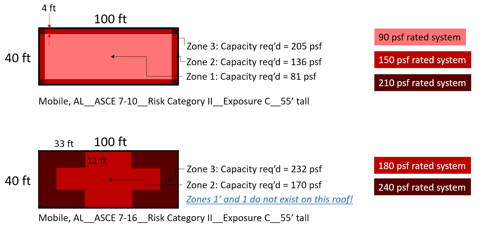
Figure 13: Roof zone layouts, design wind pressures, and the minimum wind-uplift rating for each roof zone for a 5-story apartment building in Mobile, Ala. based on ASCE 7-16 (bottom) and ASCE 7-10 (top).
The increases in DWP for the roof zones significantly increase the roof system capacity requirements for this scenario. The lack of Roof Zones 1 and 1 Prime is a significant factor in this case. The entire roof area will need a higher capacity, with much of the roof requiring a significant increase in capacity.
Figure 14 shows roof area percentages based on the required roof system capacity for this scenario.
5-Story Roof Example (Mobile, Ala.)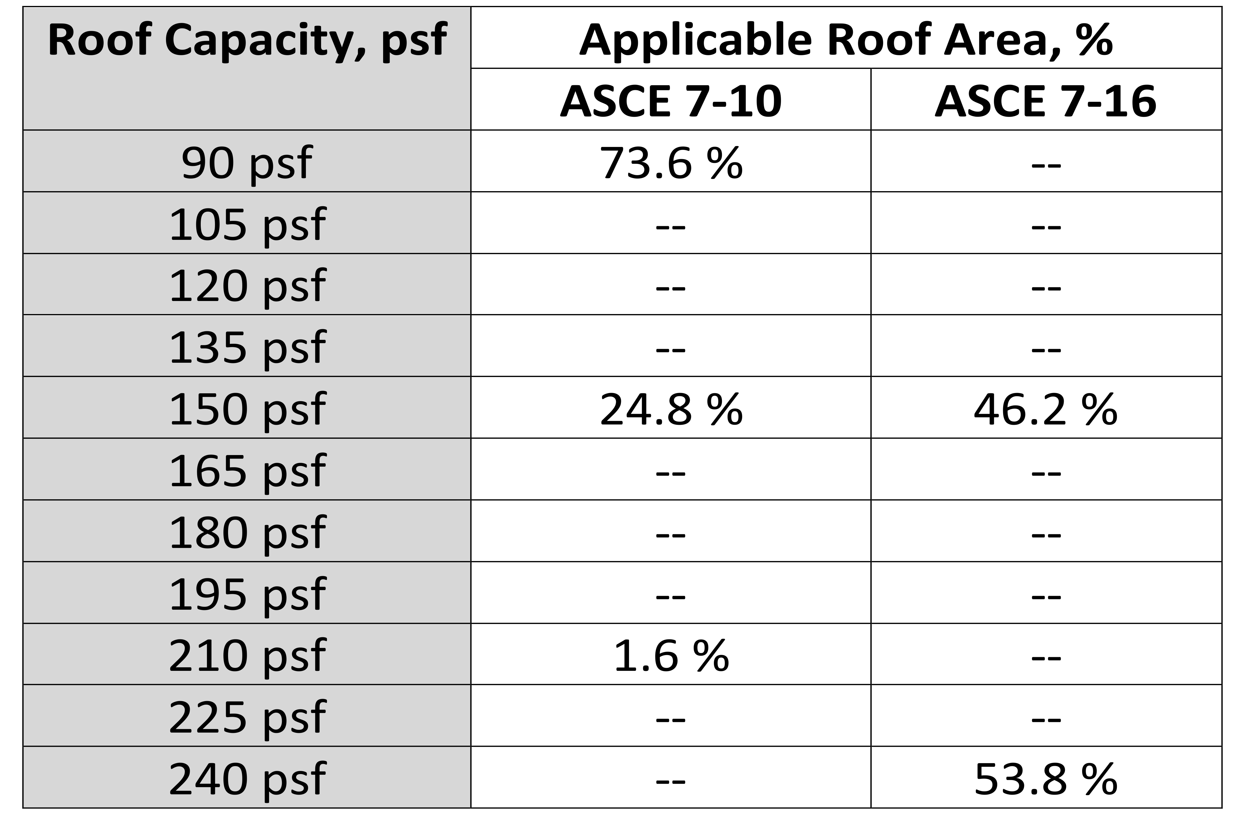
Figure 14: Required roof capacity and the roof area (%) where each is required.
Case Study Summary. A comparison of low-slope roof-system design wind pressures from a case study of two building types in two different cities was performed. Risk Category and Exposure Category were varied; design wind pressure (DWPs) were determined for 72 variants. The resulting DWPs were analyzed to begin to determine trends when comparing DWP results based on ASCE 7-10 and ASCE 7-16.
The observations from these case studies include:
- DWPs determined using ASCE 7-16 are increased in most cases.
vReductions of ASCE 7-16 DWPs are in Roof Zone 1’ (read as “one prime”), which is new to ASCE 7-16, when compared to ASCE 7-10’s Roof Zone 1.
- The largest increases in ASCE 7-16 DWPs are in Roof Zone 1.
- Due to larger (wider) roof zones and an additional roof zone, taller, smaller-footprint buildings may only have Roof Zones 2 and 3. Reductions in DWP for Roof Zone 1’ are not realized.
- Larger roof zone sizes mean larger areas of a roof are affected by increases in DWPs.
- Looking only at DWPs does not provide enough information; a comparison of required roof system capacities is needed.
Selecting Roof Systems
Selecting roof systems that have the appropriate wind-uplift capacity is primarily performed using one of the Approval Listing organizations: FM Approvals, Underwriters Laboratories, SPRI (see section below titled DORA), Florida Department of Business and Professional Regulation, Miami Dade County, and Texas Department of Insurance.
RoofNav. The “Assembly Search” function within RoofNav (roofnav.com) allows users to search the large database of Approval Listings from FM Approvals. Users input specific roof assembly features and performance requirements in order to find tested roof systems that meet the user’s requirements.
A RoofNav Approval Listing includes the roof system type, application, securement methods (for all layers), deck type, maximum slope, wind-uplift rating, internal fire-resistance rating, exterior fire-resistance rating, and the hail-resistance rating, as highlighted in Figure 15. The figure also highlights the options for securing the roof covering to the cover board. This points out that there are options available for many of the layers within the single Approval Listing. A designer may choose to specify as specifically as required to meet the owner’s performance requirements for the roof system.
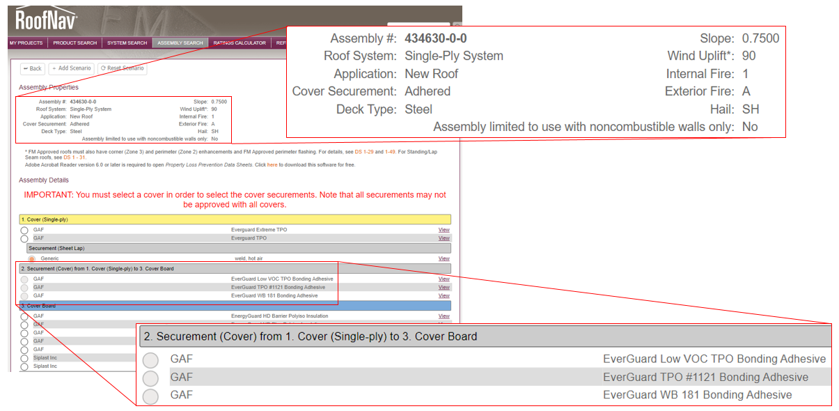
Figure 15: An example of the Information contained in a RoofNav Approval Listing.
Directory of Roof Assemblies. The Directory of Roofing Assemblies (DORA), which is provided by SPRI, the Single-Ply Roofing Institute, includes Approval Listings for single-ply and modified bituminous roof systems. Within DORA, users input material specifics and performance characteristics to find Approval Listings. A DORA Approval Listing includes a summary of the roof system, the wind-uplift capacity, and the specifics of each layer within the roof system, as shown in Figure 16. Like other Approval Listings, options exist for some or all of the layers, and designers can specify to their necessary level of detail.
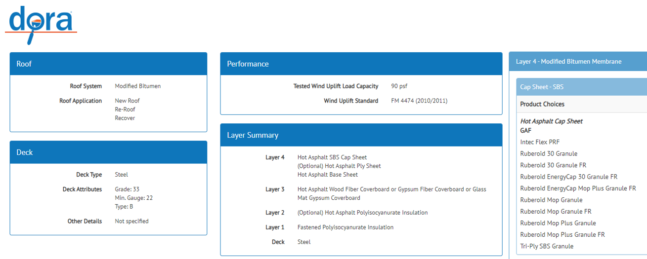
Figure 16: Example information contained in a DORA Approval Listing.
Conclusion
ASCE 7-16 DWPs are generally increasing relative to ASCE 7-10, but this impact is better understood by comparing the required roof system capacity for different building types and dimensions in different cities. Looking only at DWPs does not provide enough information; a comparison of required roof system capacities is needed. Not only did the DWPs change, but the methodology for determining the size of the perimeter and corner roof zones changed significantly in the new ASCE 7-16 version; the amount of roof area contained by the perimeter and corner roof zones increased. The case studies—of two buildings less than 60 feet tall in two cities—and corresponding analysis in this article are just one additional small step to understanding how the ASCE 7-16 will affect wind design over the next decade.
James R. Kirby, AIA, is a GAF building & roofing science architect who has authored and presented for three decades about roofing systems’ design, make-up, and efficient and long-term performance.


