Photo courtesy of Shaw Roofing
Building science is, in essence, the study of the impacts of heat, air, and moisture on the building enclosure. Through the study of building science, the design professional learns how to prevent damage from air and moisture infiltration, and how to improve the overall energy efficiency, durability, and long-term performance of buildings. Rather than viewing the elements of a building as a collection of individual and unrelated components, ensuring performance of the building enclosure requires a systems perspective. Avoiding risks in a building structure requires understanding how the increasingly complex systems required in a building come together, stay together, and perform together.
The Fundamental Science of Control Layers
It is an inescapable and universal truth that natural forces are always at work on buildings. The fundamentals of building science are found in the Second Law of Thermodynamics:
- Heat will flow from warm to cold;
- Moisture will flow from warm to cold;
- Moisture will also flow from wet to dry;
- Air flows from an area of higher pressure to one with lower pressure; and
- Gravity acts down.
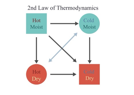
Image courtesy of GAF|Siplast
Energy, air, and moisture will flow between two zones until a state of equilibrium or balance is achieved. Understanding the preferred path of movement is the first step in knowing how to control the environment within a building enclosure.
What are Control Layers?
Control layer is the term used for the parts of the building enclosure that are designed to stop external elements from moving uncontrolled through a structure. There are four main control layers in a building: they address liquid water, air, heat, and water vapor. Whether the control layer completely stops the movement of the elements or slows down the movement depends on the materials used and the needs of the building.
In essence, the four control layers can be split into two main categories: those that manage moisture and those that manage energy efficiency. Moisture management works to prevent liquid water, water vapor, and condensation from impacting the building. Managing energy efficiency focuses on the movement of air and heat through the building enclosure. All of the control layers need to work together to achieve maximum effectiveness.
Moisture Management
Of the many challenges a building enclosure faces, water represents the greatest continuous threat. The presence of water in unwanted locations within the building enclosure can contribute to rot, decay, and biological growth. There are four primary ways moisture makes its way into a building and they all need to be considered when designing a building’s enclosure: flow of liquid water, capillary suction, air-transported water vapor, and diffusion.
The most obvious and impactful way is liquid water, or water from rain or snow. Buildings must be designed to efficiently manage or shed water by moving the water out and away from the structure. This is the primary role of the water control layer in the enclosure assembly.
Next is capillary action. This is how water moves through pores and small cracks, sometimes acting against gravity, and seeping into masonry, foundations, and any other tight spaces in the building.
The last two—air-transported water vapor and diffusion—can be the hardest to see. Moisture vapor transported in either manner can cause damage when it is allowed to condense or become liquid in a place where the liquid water cannot be managed. The materials and designs used to control air intrusion and reduce vapor diffusion are often less obvious. They must interact with the other building control layers, such as the air and thermal control layers, in order to perform.
The importance of a continuous air control layer to manage uncontrolled airflow, and the moisture it carries, cannot be overstated. Gaps and discontinuities in the air control layer within the building enclosure allow air and its associated moisture to enter the assembly. Air leakage can carry as much as 100 times the amount of moisture through a hole in the building enclosure when compared with the transport from vapor diffusion moving through the building materials. The amount of moisture air will hold is dependent on its temperature. Warm air can hold more moisture than cold air. When warm, moist air encounters a cold surface, the air will cool and the excess moisture that the air can no longer hold will condense on the cold surface, causing a problem if the water cannot be managed at that location.
Vapor diffusion through building materials can be less impactful because water vapor moves much slower in this manner. All materials used within the building enclosure have a permeance and will slow the movement of moisture vapor that is moving through the assembly by way of diffusion. Understanding the permeance of materials and how easily moisture vapor may flow through them—or not—is the first step in preventing issues caused by moisture moving in this manner.
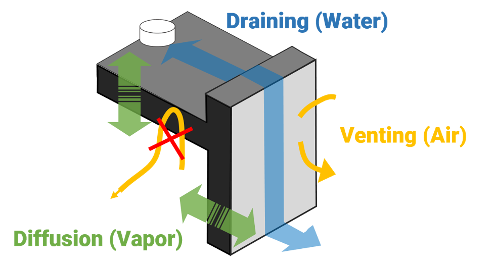
Image courtesy of GAF|Siplast
Moisture management strategies.
Using the roof-to-wall interface as an example to illustrate moisture management strategies, the first line of defense is to drain water away by directing water to roof drains and out from the wall. The next step involves venting or using airflow to pull moisture vapor out of the building enclosure assembly. The final moisture management step is managing diffusion: allowing diffusion to dry the assembly in at least one direction, accommodating any incidental moisture in the building materials to leave the assembly. The process of diffusion is slow and should be a strategy only for incidental moisture. Ensuring moisture vapor does not become condensation and liquid water where it cannot be managed in one of these ways becomes the responsibility of the thermal control layer.
Energy Efficiency Management
Managing energy efficiency of buildings relies upon both preventing uncontrolled air movement and resisting heat flow. Adding more insulation to the thermal control layer could seem to provide the answer to improving energy efficiency. However, simply adding more insulation to a building envelope soon reaches the point of rapidly diminishing returns. The real culprit behind poor efficiency is air movement.
Airflow through the building envelope is the most effective method of carrying heat and moisture into or out of a building. In order for air to flow in or out of a space, there needs to be a pressure differential across the boundary and an opening for the air to move through. Buildings become pressurized due to wind, stack effect, and heating, air conditioning, and ventilation (HVAC) systems. Wind exerts pressure on the building enclosure causing positive pressure on the windward side and negative pressure on the opposite side. Stack effect is caused by warm air rising, increasing pressures higher up in the building. Any discontinuities in the air control layer, no matter how small, will provide the opening for air along with heat and moisture vapor to move through the enclosure.
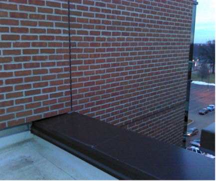
Image courtesy of SmithGroup
Airglow through the building envelope is the most effective method of carrying heat and moisture into or out of a building as shown in the FLIR image of a rising wall detail.
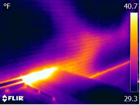
Image courtesy of SmithGroup
Air leakage has been identified as a significant, quantifiable contributor to poor building energy efficiency. According to “The Hidden Science of High Performing Building Assemblies,” Environmental Building News November 2012, air infiltration and exfiltration make up an estimated 25-40 percent of total heat loss from a building in a cold climate. Buildings in hot climates are not immune to the impacts of air leakage. In a hot climate, air leakage makes up 10-15 percent of total heat gain, increasing the energy costs to cool the interior. Losing up to one-third of conditioned air to uncontrolled airflow has a weighty impact on the operation of a building and is a significant preventable cost. Moist, hot air entering the conditioned space not only requires extra energy to cool, it also must be dehumidified. If it is not dehumidified, humid air can condense when it contacts a cooler surface, leading to damaging water buildup. These increases in energy usage are why the International Energy Conservation Code (IECC) has required the use of air barriers in building enclosures since 2012.
Control layers that address airflow not only create energy savings but also help to mitigate moisture accumulation. This interrelationship of air and moisture, and how they are controlled, leads to the importance of the interactivity of control layers.
Working Together = Success!
Given the interwoven concerns of managing air and moisture, control layers are better viewed as interconnected layers and assemblies and not just a single product or material. The enclosure is better defined as a combination of materials assembled and joined together in a system, providing a continuous barrier to water penetration, air leakage, moisture vapor intrusion and thermal movement through the building envelope.
The relative importance of each control layer is based upon the magnitude of impact it has on the performance of the building enclosure. The liquid water control layer must be addressed first. Uncontrolled liquid water in a building is extremely deleterious and failures here render other control strategies less consequential. Second in importance is the air control layer, due to its interrelationship with heat and moisture. The thermal control layer is next, as it regulates where condensation from leaked air could potentially occur. Finally, water vapor management strategies provide the final layer protection.
Any of these barriers’ effectiveness can be greatly reduced by discontinuities, even small ones. These openings can be caused by poor design, damage from other trades, improper sealing and flashing, mechanical forces, aging, and other forms of degradation. Thankfully, there are ways to avoid these discontinuities and set up a project for success.
Examining Control Layers in Action
Key Point: Each control layer serves a purpose and must be located properly to perform.
The perfect wall is an environmental separator—it has to keep the outside out and the inside in, writes Joseph Lstiburek, Principal Ph.D., P.Eng., ASHRAE Fellow, at Building Science Corporation. “In order to do this the wall assembly has to control rain, air, vapor, and heat. The best place for the control layers is to locate them on the outside of the structure in order to protect the structure. And since most of the bad stuff comes from outside the best place to control the bad stuff is on the outside of the structure before it gets to the structure.”1
How can the architect and construction team make this work? Is there a right and wrong order for control layers? As Lstiburek points out, “If you can’t keep the rain out, don't waste your time on the air. If you can’t keep the air out, don't waste your time on the vapor.”2 The first step is to ensure the layers are continuous. Any breaks in the system lead to trouble. While flat parts of the building enclosure can be designed relatively easily with a line for each control layer, managing the control layers becomes increasingly complicated at foundation, wall, and roof systems interfaces and as details, like parapets, are added.
Looking at a detail such as a parapet will help to illustrate the best practices for controlling each of these elements.
Water Control Principles
Preventing water from infiltrating the building enclosure at any point is of first concern when thinking about the building enclosure. Water control strategies should be planned in the way water flows: starting at the top, down to the bottom of the structure. The phrase “Slope to drain and then drip” also offers a good strategy summary. The water control layer must be continuous across all six sides of the building enclosure. The primary water control layer is the exterior surface of the structure, with a potential secondary water resistive barrier further into the assembly providing a final stopping point. Any interfaces of materials and assemblies must be lapped with the top material coming over a lower material. This lapping prevents a potential lip where water can sit and eventually work its way into the building. All membranes and flashing should be continuous under coping, with coping sloped inward toward roof drains. Drip edges on the outside of coping as well as on all other horizontal surfaces are vital to sending bulk water out and away from the building and preventing capillary action from bringing water back into the enclosure.
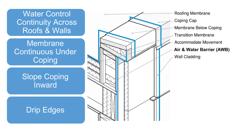
Image courtesy of GAF
Water control principles at the roof-wall interface.
Air Control Principles
The goal of an air control layer is the prevention of uncontrolled air movement. There are three main types of air movement through a building enclosure assembly: infiltration, exfiltration, and intrusion.
The most common forms of uncontrolled air leakage are infiltration and exfiltration, where outside air travels into or out of the building respectively. Infiltration and exfiltration are what is measured through air leakage testing. The IECC sets limits on these measurements when whole building airtightness testing is required. Air intrusion occurs when air within the building travels from conditioned space into unconditioned areas within the building enclosure, such as into the roof assembly or floor line space. It moves through the space, and then back into the conditioned part of the building. While this movement is not classified by the building or energy code as air leakage, it can still cause issues due to the heat and moisture that it brings into areas of the building that may not be designed to manage it. For example, in a cold climate, interior air that travels into the roof assembly can cool and create the potential for condensation. Condensation on the roof deck can lead to mold and decay.
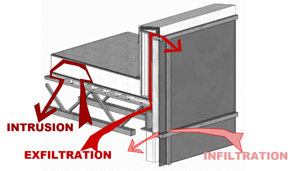
Image courtesy of GAF
Methods of air movement within a building.
To prevent the uncontrolled movement of air through the building enclosure, the air barrier must be made of systems and assemblies—a combination of materials working together—to prevent air leakage. The air control layer must be continuous across roofs and walls and must have continuity at interfaces. Per Section C103.2.1 of the IECC, it is the designer of record’s responsibility to detail the continuous air barrier around the entire building enclosure.
Several different roofing materials will block air and can be classified as an air barrier material. In order to fully function as the air control layer and be part of an air barrier assembly, these materials need to be installed and tied into penetrations and the wall assembly in such a way as to ensure airtightness at the interfaces. Consider how a roof membrane often runs up and over a parapet wall or is flashed at an exhaust pipe: the building designer needs to specify that the membrane not just overlap the wall air barrier or surround the pipe, but also that it is flashed and sealed to both in such a way that air cannot escape.
Thermal control principles
The thermal control layer follows the same principles as the other control layers. The thermal control layer is designed to resist the movement of heat from one side of the building enclosure to the other. Continuous insulation is unambiguous in the code, within IECC as well as the referenced ASHRAE 90.1. IECC C103.2 depicts the thermal envelope, and thermal bridging requirements are covered in IECC 402.7.5. Solutions for details like parapets will depend on construction type, location of insulation in the wall and roof assemblies, and design preference for the boundary of the conditioned space. Any breaks in the thermal control layer or insufficient insulation will increase the risk of condensation occurring at that location, whether it be from humidity in the conditioned space or uncontrolled water vapor entering the assembly from elsewhere.
Vapor control principles
The vapor control layer can be the most challenging of the control layers. The vapor control layer is responsible for slowing the movement of moisture vapor through the building enclosure. As defined by the IBC, moisture vapor will stop moving at a material with a permeance of <0.01 perms when tested to ASTM E96. As such, a separate vapor retarder or vapor barrier may not be required and may actually cause damage to the structure if used improperly.
To avoid unintended consequences, the designer should first be aware of the vapor permeance of all the layers in the enclosure and verify the location of any low permeance vapor retarders in the assembly. If there is more than one low permeance vapor retarder in the assembly, moisture can get trapped between layers, leading to condensation and related issues. Ideally, the material with the lowest vapor permeance should be placed on the warm side of the enclosure assembly. To help ensure there is no issue with moisture vapor such as condensation occurring in the wrong location, a moisture analysis can be performed. Hygrothermal analysis such as WUFIⓇ can provide this information, but it also relies upon the assumption that there is a perfect air barrier installed. For these reasons, a separate vapor control material may not always be needed. The decision matrix for where a vapor retarder is located within the assembly comes down to building use, climate zone, the design of the enclosure, and outside humidity levels that need to be considered.
One area where vapor retarders can be beneficial is in low-slope roof decks. They can also be beneficial in buildings with large temperature differences from interior to exterior and with building uses that require high interior moisture levels, either from use or during construction. Additionally, a vapor retarder is advantageous above concrete roof decks where curing moisture can cause issues for the rest of the roof assembly.
Case Study: Examining Parapet Perplexities of the Control Layers
Parapets are a critical interface where building aesthetics meet performance. The 2018 International Building Code (IBC) defines a parapet as “the part of any wall entirely above the roofline.” It is also the junction where building aesthetics combines with structural performance, air and moisture management, energy efficiency, construction trade sequencing, and operational maintenance. At such a critical interface, proper detailing, installation coordination, and execution are paramount.
Most of the components of a roof system limit air infiltration and can be considered as air barriers. Is there a best practice location to stop the formation of condensation within the roof system?
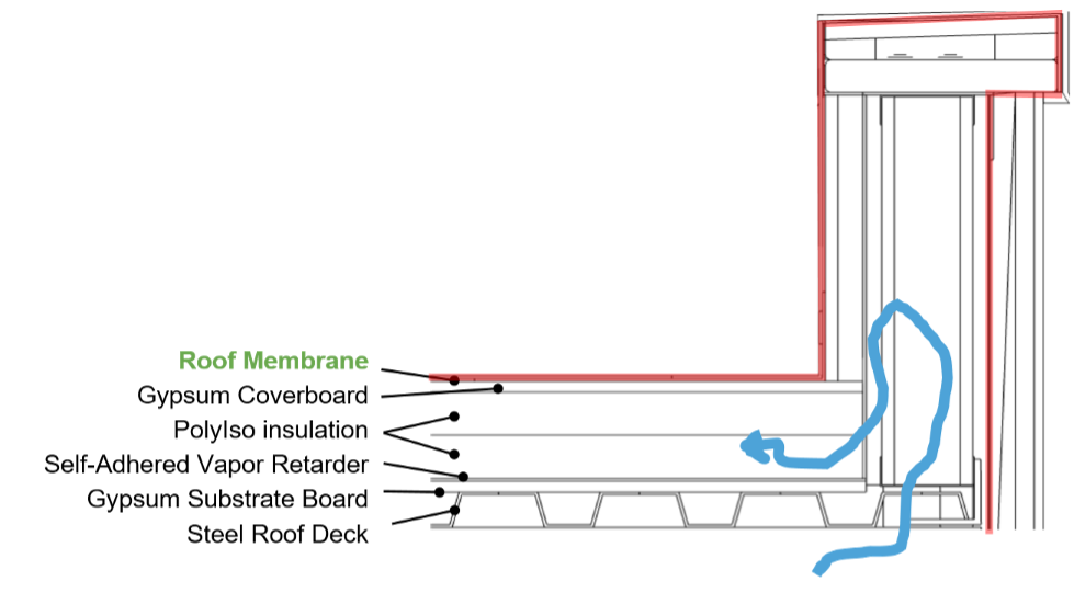
Image courtesy of GAF
Image 7.
If the roof membrane is designed and installed as the continuous air barrier going up and over the outside of the parapet, tying into the air barrier in the wall assembly, then air intrusion can potentially condense on cold surfaces within the roof assembly or under the top of the parapet. This is because conditioned interior air, as shown by the blue arrow in Image 7, can travel into the parapet. If any of these components or surfaces are below the dew point, moisture in the air will condense. Condensation is what can cause issues in this part of the building enclosure.
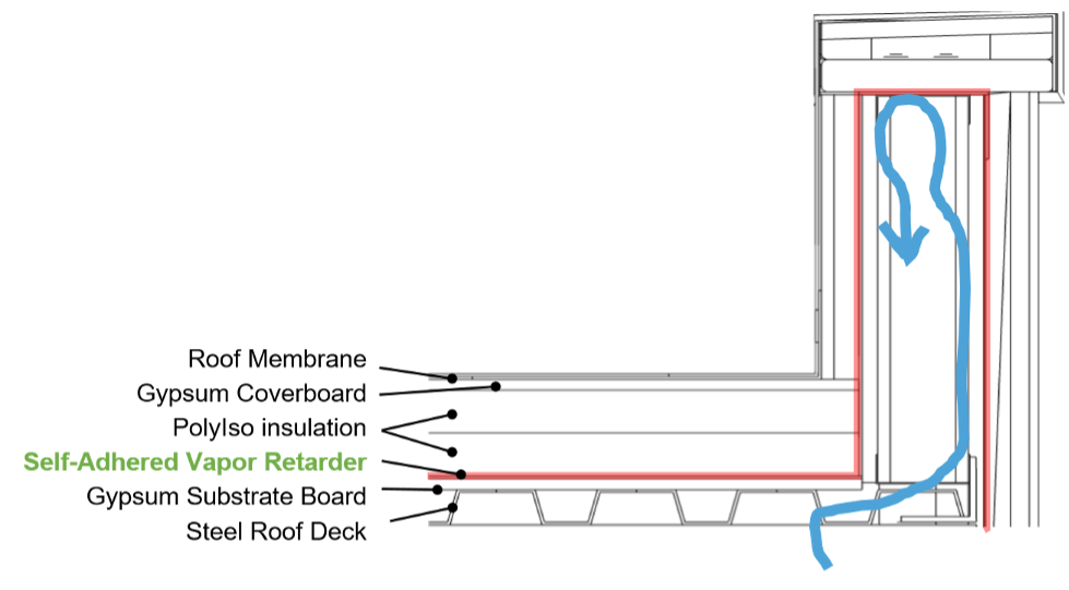
Image courtesy of GAF
Image 8.
Instead, a vapor retarder on the roof deck can be installed as and function as the air barrier. This will make it easier to bring the air barrier onto the inside of the parapet and interior to the insulation. Any air intrusion, as depicted by the blue arrow in Image 8 is less than in the previous option and there is no risk of moisture getting into the roof insulation. This configuration certainly helps prevent air intrusion in the roof system but may still allow air up into the parapet. Condensation may still occur on cold surfaces, especially if the top of the parapet has insufficient insulation.
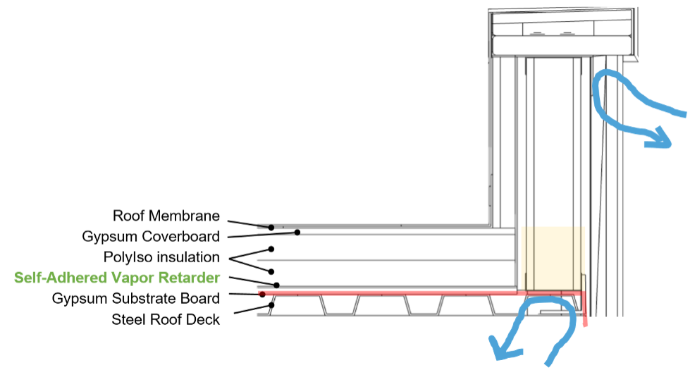
Image courtesy of GAF
Image 9.
One final option as shown in Image 9 is to remove the parapet from the conditioned space entirely. This starts in the same manner as the previous example with a self-adhered vapor retarder installed as the air barrier on the roof deck. The parapet is then at least partially filled with insulation allowing the air barrier to continue along the base of the parapet wall and connect to the wall air barrier. This placement keeps the air barrier on the warm side of the insulation in winter and prevents warm, moist air from getting up into the parapet cavity and roof structure where condensation could cause harm. This assembly design is now controlling air intrusion as well as air leakage across the building enclosure. If there are further concerns for a particular building, hygrothermal analysis can help determine if any condensation is likely to occur.
Proper Sequencing and Design of Control Layer Continuity
Key Point: Drawing the lines for all 4 control layers at each specific detail will help check for continuity.
These are some key strategies to maintain continuity of each of the control layers:
- Water control is managed first by the roof membrane and the cladding. A secondary water control layer, in the form of a water-resistant barrier or WRB, is often found in the wall assembly applied to the sheathing, typically behind or below the exterior insulation.
- Air control can be managed at the deck level of the roof, which can more readily be linked into the wall air barrier. The roof membrane can also be used as an air barrier as long as the detailing and transitions are done carefully.
- Thermal control continuity is maintained by connecting the roof and wall insulation, which can be challenging. This is easiest with continuous insulation on the outside of the structure. It is important to be mindful of cavity insulation or designs where insulation is split between inside the cavity and outboard of the structure, as there are potential risks for condensation due to the thermal bridges of the structure.
- Vapor control can be in the same plane and the same materials as the air control layer, depending on the building location needs, construction methodologies, product choice, and occupant use of the building.
Defining Continuity
The four key control layers (water, air, thermal, and vapor) should generally be continuous across all six sides of the building enclosure. The “pen test”—tracing each of the control layers around the building enclosure—is a helpful tool to design and communicate the intent of the critical components and functions of the building enclosure. The “pen test” is relatively easy in theory, but it can get complicated when the designer factors in the control layers at each condition, penetration, and transition. The pen test should be performed not only on the plans and elevations, but on the interface detail drawings where multiple materials and trades intersect.
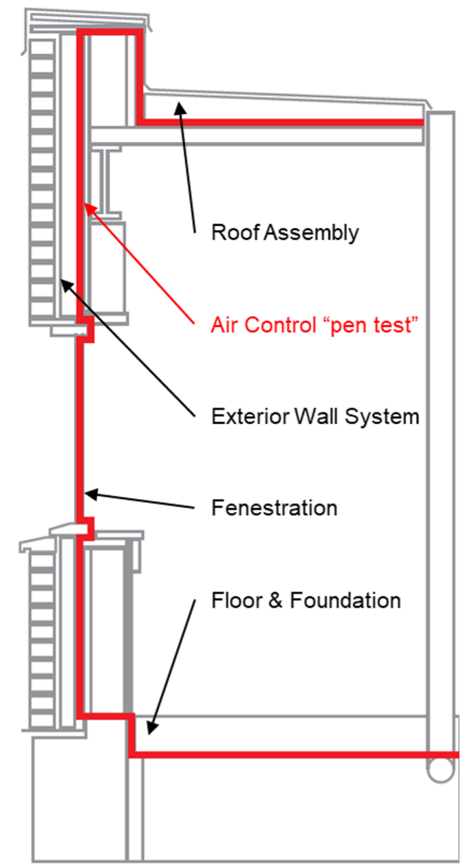
Image courtesy of GAF
Example of a “pen test” shown, as a red continuous line is drawn across building envelope elements to verify no gaps exist.
Identifying and maintaining continuity of the four key control layers is important in the design phase. Detailing and identification of the control layers in the drawings is critical to ensuring that the design intent is implemented in the field. This can require the design and specification callouts to be very specific. If the sequencing of components or trades in the field impacts the intended continuity or performance of the control layer in the design, it needs to be addressed before construction starts to prevent rework.
At a critical interface like a parapet, proper detailing, installation coordination, and execution are paramount. Control layer discontinuities can lead to failures in the field. For instance, air leakage can lead to concealed condensation and interior moisture damage.
Low-Slope Roofs and Wall Air Barrier Assemblies
One problem confronting the design professional is that there are lots of ways to accomplish performance goals for the building. The questions of how to design and sequence the control layers to prevent issues in the building are not simple. The building code can further complicate the picture, as it requires both ambiguous and specific things. For example, air and thermal barriers need to be continuous. Exterior walls and roof assemblies requirements are separated, but flashing requirements tie them together.
The International Energy Conservation Code (IECC) is a building code created by the International Code Council in 2000. It is a model code adopted by many state and local jurisdictions in the United States for the establishment of minimum design and construction requirements related to energy efficiency. In 2012, the IECC first published air barrier requirements which state that “continuous air barriers shall be provided throughout the building envelope.” There are exceptions to this requirement, but these are diminishing with each new version of the code.
There are three ways of achieving compliance with air barrier requirements:
- Materials (i.e. prescriptive)—the IECC published a list of materials they consider to be air barriers. Materials not on the list must be tested and shown to have an air permeance ≤ 0.004 cfm/ft2 under pressure differential of 0.3 in. water gauge (w.g.) tested in accordance with ASTM E 2178.
- Assemblies—assemblies consist of materials and components (sealants, flashing, etc.) that when put together can create a continuous air barrier, inclusive of penetrations. An average air permeance ≤ 0.04 cfm/ft2 under pressure differential of 0.3 in. w.g. tested in accordance with ASTM E 2357, 1677, or 283 is required.
- Whole building airtightness testing—the air leakage rate of a completed building enclosure can be tested and confirmed to be ≤ 0.40 cfm/ft2 at a pressure differential of 0.3 in. w.g. per ASTM E779, ASTM E3158 or equivalent method approved by a code official. Whole building airtightness testing will no longer be just an option for most buildings starting with the 2024 IECC, making the continuity of the air control layer even more critical to a building’s success.
The use of vapor retarders in low-slope roof assemblies will determine how the different control layers are detailed at transitions and at the roof-to-wall interface. All vapor retarders prevent air movement, but not all air barriers stop vapor diffusion. That means that when design professionals designate the use of a vapor retarder in a roof system, that retarder is also acting as an air barrier. The caution when using the vapor retarder as the air control layer is that the vapor retarder needs to be sealed at all perimeters and penetrations in order to perform as part of the air barrier assembly. It needs to be flashed and sealed to the wall air barrier, so air does not penetrate the interface. Practically speaking, all vapor retarders are air barriers if they are installed continuously and sealed to block the passage of air.
Case Study: Construction Sequencing of Control Layers for a Balloon Parapet
Sequencing of construction is very important for the execution of the continuous control layers. Understanding how each of the details will be constructed and how the different trades will interact with each other during the installation process will ensure that each of the control layers is continuous. By thinking through this sequencing, and even detailing out the installation sequence for complex details, clarity will come to all parties involved.
In this example of a balloon parapet, fore-thought in the process is ideal. Once the roof deck is laid and the wall is framed and sheathed, place a piece of flashing over the roof-to-wall interface below where the parapet will be constructed. This flashing will allow for easy integration to the wall air barrier and allow for the layers to be properly ship-lapped, providing continuous water and air control between the roof and the wall assemblies. This loose piece of flashing on the corner allows future materials to tie in when installed. After the flashing is laid, the parapet is then constructed over it in a balloon-framed configuration.
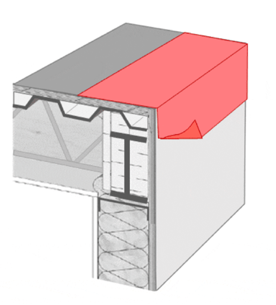
Image courtesy of GAF
Image 11 and 12. Sequence of Installation. Pre-treated corner and parapet wall.
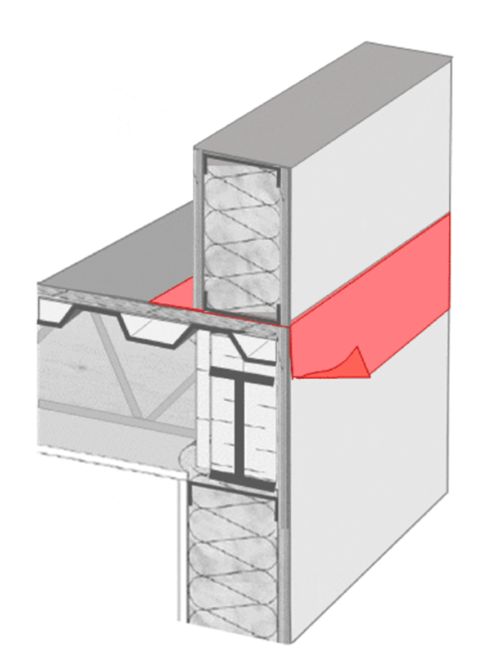
Image courtesy of GAF
Image 12.
Next, the remainder of the air barrier is applied to both the roof and wall systems, lapping over the previously installed flashing on the roof and over the top of the parapet. The flashing over the top of the parapet should lap over the wall air barrier, which itself laps over the flashing installed before the parapet was built. This creates full integration between the assemblies and provides proper lapping of the different layers. The air barrier on the remainder of the wall must lap under the flashing at the roof-to-wall interface.
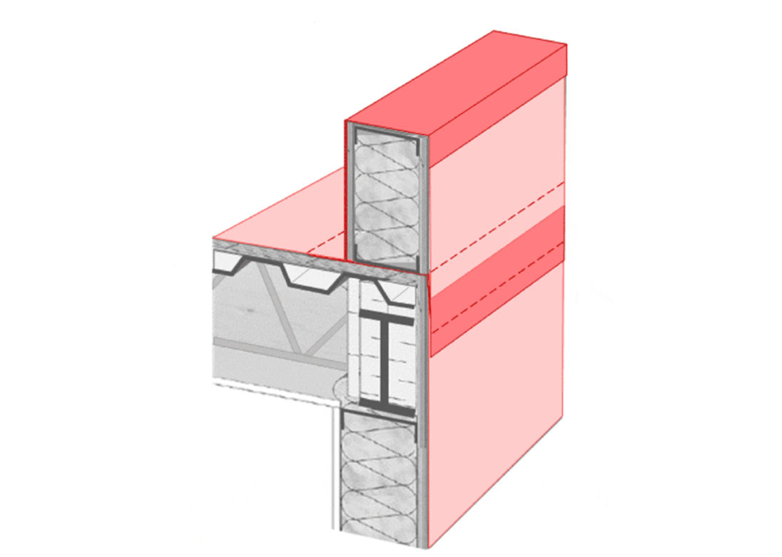
Image courtesy of GAF
Image 13. Air barrier integrated through interface.
Next, continuous insulation is installed as required by code. This provides the thermal control layer. Insulation is applied to the roof deck, back-side of the parapet wall, and exterior wall to maintain continuity. Ideally, there should be insulation on top of the parapet wall as well, especially if there is no insulation within the parapet itself. Redundancy and sufficient shingle- or ship-lapped insulation is important on the low-slope roof, as this installation method takes into account the expansion and contraction of layers that may occur during the life of the building and provides room for materials to shift without breaking continuity. Exterior wall flashing is installed to maintain shiplap and provide water control continuity at the area where the roof membrane will terminate.
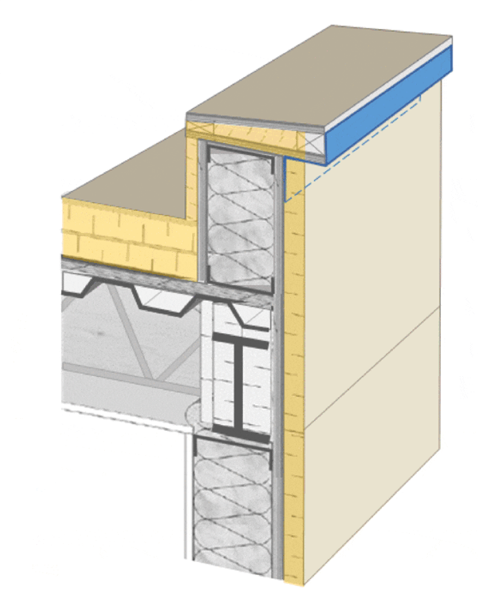
Image courtesy of GAF
Image 14. Continuous insulation installed (yellow).
The roof membrane is installed next. The roof membrane continues to the horizontal roof edge and is extended up the backside of the parapet wall. Depending on the roof membrane used, it can either continue up over the top of the parapet, or an additional piece of flashing will transition from the roof membrane, up over the parapet and terminate over the previously installed exterior wall flashing.
The outer water control layer on the wall assembly is never relied on to perform without any leaks, so a secondary membrane and control strategy is necessary. Typically, the air barrier material and assembly will also perform as the secondary water resistant barrier. The exterior wall flashing should be tied into and properly lapped onto the secondary water resistant barrier.
Finally, ANSI/SPRI ES-1 compliant coping is lapped over the cladding and the roof membrane or flashing with drip edges on both sides. It should also maintain an overall slope towards the roof system to shed water. It is important to have a negative slope off the coping, directing water back onto the roof and ultimately to the roof drains. The coping should also include drip edges to prevent water wicking up under the coping. When detailing and doing the “pen test” on the water control layer that has just been shown, it is critical that the line be continuous along the entire roof and wall.
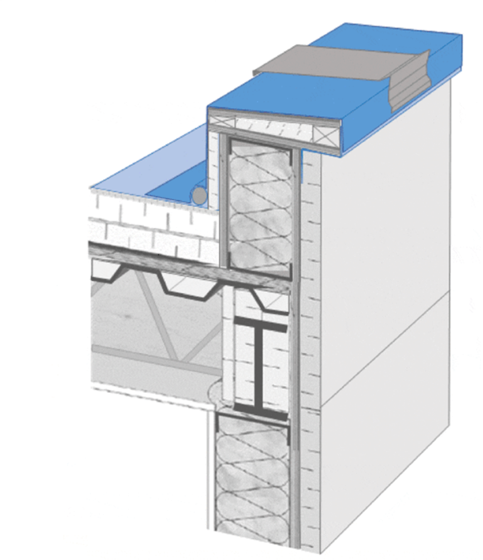
Image courtesy of GAF
Images 15. Roofing membrane installed followed by coping and cladding.
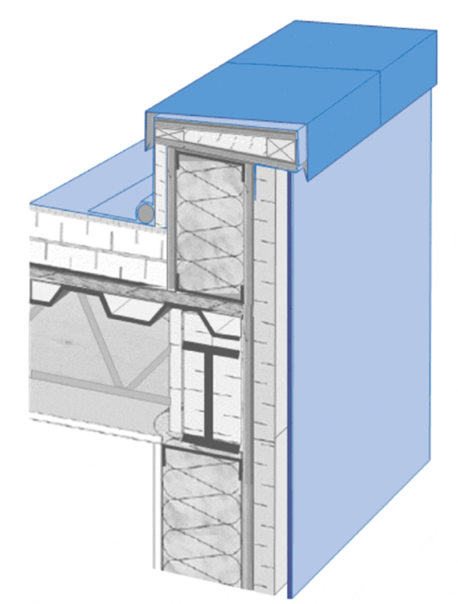
Image courtesy of GAF
Image 16. Roofing membrane installed followed by coping and cladding.
Thinking through how the roof assembly terminates and ties together at the interface of the wall and roof also has long-term ramifications for performance, maintenance, service, and potential re-roofing. The design team should consider the maintenance part of the lifespan of the building as well. Understanding the maintenance requirements and how a building manager will need to take care of these items over time will highlight if the details need to be adjusted for long-term performance. When the building is re-roofed, it is important that the design has enough vertical height to lay a new roof without reinstalling cladding, to properly terminate the new roof membrane into the existing wall assembly control layers and that there is necessary space available to include any additional insulation when a new roof is placed.
Specification for Successful Projects
Key Point: A specification requiring continuity of control layers, communication between trades, verification of material compatibility, and quality control is critical to success.
There are a few key items that designers can include in their specifications to help ensure the control layers will be installed properly and that the interface details are not missed. The specification sets up communication between all parties throughout a project and puts potential problems under a continual, multidisciplinary spotlight that helps a team to catch them as early as possible, even during the design stage. Items such as defining the complete scope of work for the contractors installing the different control layer assemblies and specifying the party responsible for installing flashing and transitions between systems assigns responsibility and allows for easier scheduling and quality assurance in the field.
First, require shop drawing submittals that include details at the many interfaces around the building enclosure. This will confirm everyone understands how the materials are to be installed and who will install them. This will also highlight areas that may have been missed in specifications as to which trade is responsible for which part of a specific detail. Critical detail locations are often difficult to illustrate on two-dimensional drawings. They can require exploded diagrams and sequenced information to better communicate the design intent.
Next, the materials selected for each part of the system need to be vetted. Questions such as will the materials adhere to each other, are they chemically compatible, and can they be installed in the order required, should be answered before construction starts. This information should be easily available from the manufacturers chosen, along with support to assist in any detailing questions. If substitutions are made, compatibility and adhesion of the components needs to be reconfirmed.
Additionally, architects can specify mockups in the project documents and even require performance testing of the mock-up to confirm interfaces are functioning as intended. This helps to flush out the constructability of the design and anticipate issues that may arise during construction. Mock-ups can also help installation crews by being a reference as to agreed upon methods and providing a reference for any new crew members on the project. Having a physical example allows for confidence that, when the roof and other assemblies are installed, the team can feel assured that it will perform the way it was designed to.
Finally, quality control and operational maintenance are ways to ensure long-term performance of the building enclosure. It is important to have quality assurance and quality control occur throughout the project and not be confined to a final walk-through in the field. Fixing issues or missed details at the “almost done” stage is very hard when faced with sequencing realities.
There are four critical components to a robust detail: the material, its installation, simplification of the detail where possible, and thorough communication among design and installation professionals. Four quick checks can help design professionals ensure these are met.
They are:
- Material: are the selected materials compatible, will they adhere?
- Installation: how are the control layers installed and interfaced, what is the order of operations?
- Simplify: can fewer materials be used, or installation done in fewer steps to avoid confusion in the field?
- Communication: is the whole team engaged in conversation to create a multidisciplinary approach?
Architects strive to achieve a building that strikes a delicate balance between aesthetics and performance. From the architect's perspective, one of the biggest challenges is meeting this design vision without jeopardizing performance. This is highlighted most at the roof-to-wall interface. Blending high-performance with aesthetics means making the functional elements, like control layers, essentially invisible to the naked eye but still have them perform as designed. With any project, there are a number of factors to consider when choosing the right design: overall performance, sustainability profile, potential risks, and more. Understanding building science and creating robust control layer details and specifications helps professionals deliver better solutions for their customers.
End Notes
1Lstiburek, Joseph. “BSI-001: The Perfect Wall." Building Science.com Corporation. July 15, 2010. Accessed June 7, 2023.
2Ibid.
Andrea Wagner Watts is the Building Science Education Manager for GAF, engaging with industry professionals to provide guidance, technical support and education for roof and wall assemblies. With more than 15 years of experience in the industry, Andrea strives to improve the overall performance of the building enclosures through application innovation, product development and building science research. Andrea has published on building science, assembly interfaces, durability and resilience and holds multiple patents. She serves as an executive board member of ABAA, is the co-chair of their Technical Committee and chairs the ASTM E06 Task Group on air barriers.


