This CE Center article is no longer eligible for receiving credits.
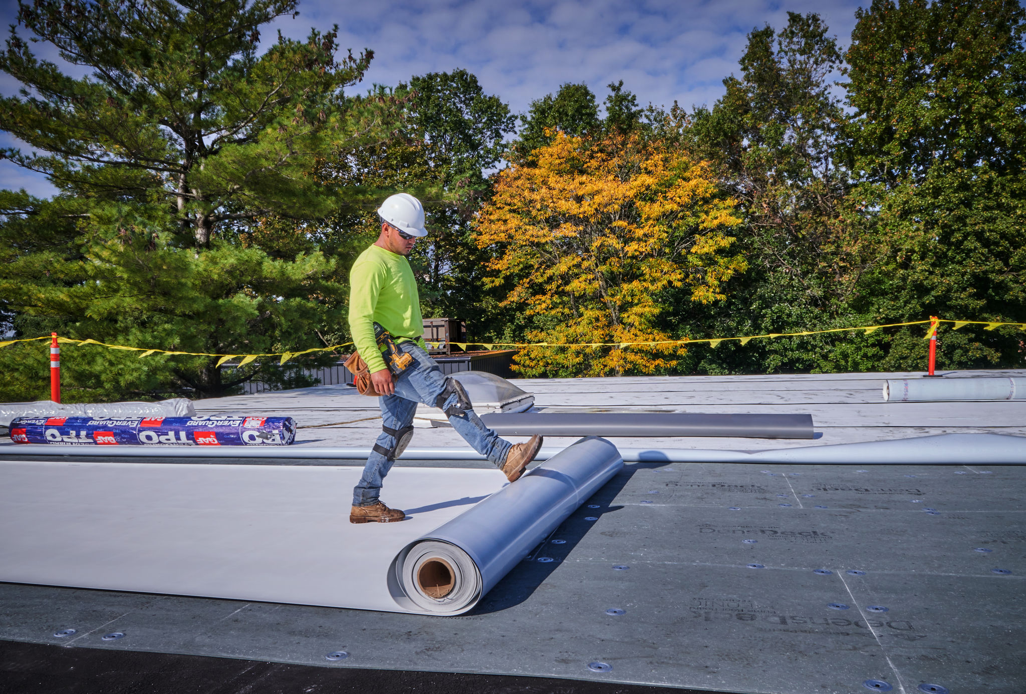
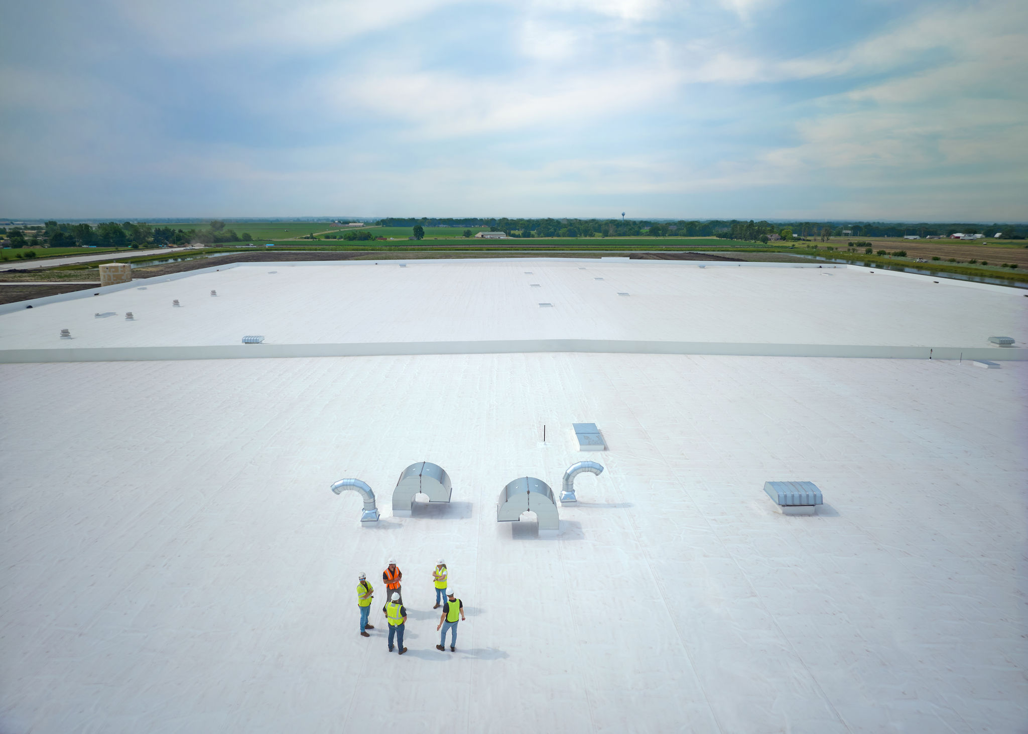
While some attribute success to being at the right place at the right time, roofing success is more about thoughtful design and installation rather than happenstance. Roofing plays an extremely important role in protecting the building from the elements, impacting energy efficiency, and contributing to the resilience goals of a building. Selection of every roofing assembly component, from the insulation to the membrane, including the attachment method can impact both the service life and the performance of the roof assembly. A successful roof design, which incorporates the building’s design parameters, will withstand the test of time.
All Images courtesy GAF I Siplast
Setting the Right Requirements—The Code
Codes provide the minimum requirements for construction. Code represents a baseline for design and has few regulatory provisions that focus on resilience. Designers can, and often should, design beyond the minimum code requirements to improve the durability and longevity of their buildings. The code requirements come from the International Building Code® (IBC) and the International Energy Conservation Code® (IECC), and are either performance or prescriptive requirements. The code also references specific key standards from documents issued by organizations including ASTM International (ASTM), ASHRAE (The American Society of Heating, Refrigerating and Air-Conditioning Engineers), and The American Society of Civil Engineers (ASCE).
Building Code Prescriptive Requirements
Chapter 15 of the IBC provides minimum requirements for the design and construction of roof assemblies and rooftop structures. The chapter addresses Roof Drainage (1502), Weather Protection (1503); Requirements for Roof Coverings (1507); Flashing (1503.2); Coping (1503.3); Wind Resistance of Roofs (1504.1, ASCE 7); and Edge Securement, Low-slope Roofs (1504.5). Such sections include requirements for emergency overflow drainage, gutter securement, and the ability of roofs to withstand wind events, foot traffic, and fires. While these topics may seem obvious to include, roof coverings must be designed and installed in accordance with this code and the manufacturer’s approved instructions. First, code considerations must be taken into account during roofing materials selection and installation. Then, they can be enhanced for each unique roof design.
Energy Code—Commercial Requirements
The IECC recognizes the roof’s role in energy performance. Energy codes apply to roofs because the R-value established in the roof assembly enables containment of conditioned air inside the building. The roof's contribution towards maintaining the enclosure and keeping the interior environment separate from the exterior means that heating, ventilation, and air conditioning (HVAC) systems do not have to work as hard, resulting in reduced energy consumption.
Under IBC Chapter 13, Energy Efficiency, “Buildings shall be designed and constructed in accordance with the International Energy Conservation Code - 1301.1.1.” Designs can comply with either the requirements of ANSI/ASHRAE/IESNA 90.1 or the requirements of the IECC Commercial Provisions, which apply to all buildings except for residential buildings 3 stories or less in height.
The version of the Code is adopted at the state level; the most recent version is dated 2021, where significant updates were made in regards to the air barrier requirements. Since 2010, the IECC states that a continuous air barrier must be provided throughout the building thermal envelope (2021 IECC §C402.5.1. Air Barriers). The air barrier is permitted to be located on the inside or outside of the building envelope, located within the assemblies composing the envelope, or any combination thereof. The air barrier selected needs to comply with Sections C402.5.1.1 for materials and C402.5.1.2 for assemblies. This section is important as the roof air barrier, whether a dedicated air barrier or the roofing membrane as the air barrier, is required to be continuous across the roof as well as continuously transitioned to the exterior wall air barrier. This requirement is critical to understand when detailing the roof at both roof penetrations (discontinuities) and at the roof to exterior wall interface.
The energy code additionally sets requirements for thermal performance, including a minimum R-value for the roof. This R-value is based on climate zone and geographic location (IECC C301.1 and 90.1 Annex 1). It should be noted that the R-values in the Code are denoted as minimum R-values. The unique building type should be taken into account when designing the R-value for the roof. Owners selecting to achieve higher energy savings, or specialty buildings such as cold storage, frequently require more insulation than required by the Code.
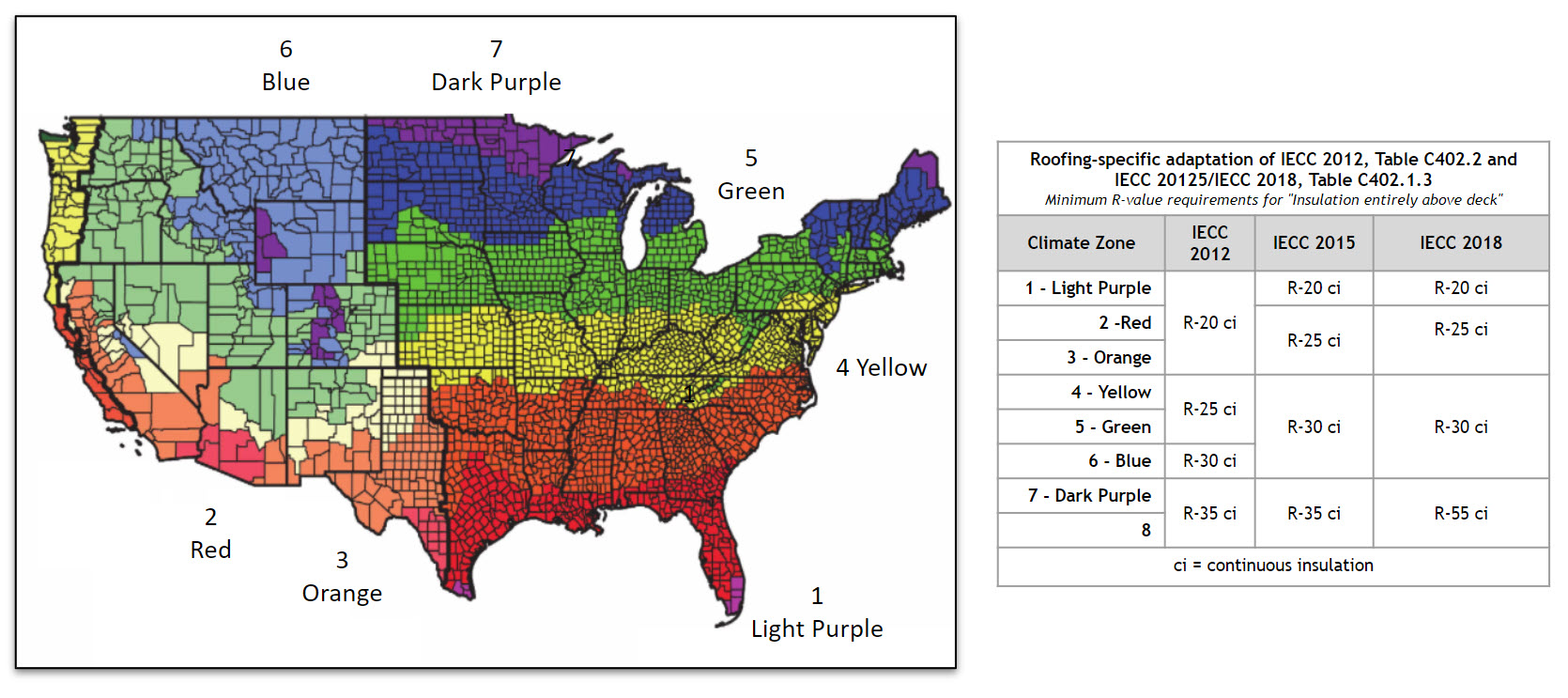
IECC Map with minimum R-value requirements.
Guidelines for installation, as provided by the codes, are also critical to achieving predicted energy efficiency. Starting in 2018, the IECC Section C402.2.1 requires two layers of insulation at the roof and provides that this installation should be staggered and offset during installation, to prevent airflow between the joints.
Wind Design
Determining the wind loads affecting a roof system is based on requirements contained in the IBC and the American Society of Civil Engineers (ASCE) 7, Minimum Design Loads and Associated Criteria for Buildings and Other Structures.
Wind mapping tools, such as the ASCE 7 Hazard Tool, helps select a location-based wind speed (in miles per hour, mph) that is used to determine the loads that will be acting on the roof system.
Recent building codes have become more stringent in determining design wind loads for roof systems. The requirements are based on historical data that has been collected over decades. Variables, such as the local building code and building dimensions, building use, occupancy, exposure, and type, are also used in various equations to determine loads acting on a roofing system. The wind speed, in miles per hour, is then converted into a wind uplift pressure, in pounds per square foot (psf). It is these wind uplift pressures that the roof assemblies must be able to withstand.
The main objective is to have the capacity of the roof greater than the projected wind loads. Wind uplift pressures will vary for each unique building and therefore, calculating the wind pressures for each roof is imperative.
Please see below for further resources and information on Wind Design:
Wind Design and (the new!) ASCE 7-16
Prevailing Winds and Prevailing Codes, A Summary of Roof Related ASCE 7-22 Changes
Establishing the Right Design Parameters
Design parameters provide the starting point to determine which roofing assembly to install on a property. It is these requirements that shape the building design, including building envelope and structural considerations. Owner requirements, including building type and use will dictate some design parameters for the roof, with the code, including regional and local climate factors setting the remainder of the requirements. Selection of the roofing assembly will influence service life and energy savings over the life of the roof. Selecting the right roof ultimately means mitigating risk and ensuring that the roof will perform as intended.
Building Use
The building use, including rooftop use, may have the most impact on a building design. The interior spaces will influence the building shape, size, and interior conditions, all of which influence the roof design. The roof will need to incorporate desired energy considerations, which influences the amount of insulation. Airflow, vapor drive, and moisture potential, will each influence the roof assembly as consideration of a dedicated air or vapor retarder may be required based on interior conditions.
While these are not all roof design considerations, these are some to consider or some questions to be asking:
Are there requirements for impact resistance?
- Consider an appropriate coverboard based on the type of impact resistance required. Foot traffic may require a coverboard with less compressive strength whereas impact requirements for hail, such as very severe hail, will require a coverboard with more compressive strength. A thicker and more robust membrane will also provide impact resistance.
Is there a particular level of fire resistance required?
- Consideration may be given to a fire rated assembly.
Will there be exercise rooms or shower facilities that may increase the moisture level in the building?
- Consider a dedicated vapor retarder at the roof deck level to prevent moisture from entering the roof assembly.
Will enhanced chemical, or grease and oil resistance be required, such as from food processing or cooking operations?
- Consider a membrane that will be resistant to the chemicals, greases, or oils that may be expelled onto the roof. Membrane types will differ on their resistance to each type of chemical.
While some attribute success to being at the right place at the right time, roofing success is more about thoughtful design and installation rather than happenstance. Roofing plays an extremely important role in protecting the building from the elements, impacting energy efficiency, and contributing to the resilience goals of a building. Selection of every roofing assembly component, from the insulation to the membrane, including the attachment method can impact both the service life and the performance of the roof assembly. A successful roof design, which incorporates the building’s design parameters, will withstand the test of time.
All Images courtesy GAF I Siplast
Setting the Right Requirements—The Code
Codes provide the minimum requirements for construction. Code represents a baseline for design and has few regulatory provisions that focus on resilience. Designers can, and often should, design beyond the minimum code requirements to improve the durability and longevity of their buildings. The code requirements come from the International Building Code® (IBC) and the International Energy Conservation Code® (IECC), and are either performance or prescriptive requirements. The code also references specific key standards from documents issued by organizations including ASTM International (ASTM), ASHRAE (The American Society of Heating, Refrigerating and Air-Conditioning Engineers), and The American Society of Civil Engineers (ASCE).
Building Code Prescriptive Requirements
Chapter 15 of the IBC provides minimum requirements for the design and construction of roof assemblies and rooftop structures. The chapter addresses Roof Drainage (1502), Weather Protection (1503); Requirements for Roof Coverings (1507); Flashing (1503.2); Coping (1503.3); Wind Resistance of Roofs (1504.1, ASCE 7); and Edge Securement, Low-slope Roofs (1504.5). Such sections include requirements for emergency overflow drainage, gutter securement, and the ability of roofs to withstand wind events, foot traffic, and fires. While these topics may seem obvious to include, roof coverings must be designed and installed in accordance with this code and the manufacturer’s approved instructions. First, code considerations must be taken into account during roofing materials selection and installation. Then, they can be enhanced for each unique roof design.
Energy Code—Commercial Requirements
The IECC recognizes the roof’s role in energy performance. Energy codes apply to roofs because the R-value established in the roof assembly enables containment of conditioned air inside the building. The roof's contribution towards maintaining the enclosure and keeping the interior environment separate from the exterior means that heating, ventilation, and air conditioning (HVAC) systems do not have to work as hard, resulting in reduced energy consumption.
Under IBC Chapter 13, Energy Efficiency, “Buildings shall be designed and constructed in accordance with the International Energy Conservation Code - 1301.1.1.” Designs can comply with either the requirements of ANSI/ASHRAE/IESNA 90.1 or the requirements of the IECC Commercial Provisions, which apply to all buildings except for residential buildings 3 stories or less in height.
The version of the Code is adopted at the state level; the most recent version is dated 2021, where significant updates were made in regards to the air barrier requirements. Since 2010, the IECC states that a continuous air barrier must be provided throughout the building thermal envelope (2021 IECC §C402.5.1. Air Barriers). The air barrier is permitted to be located on the inside or outside of the building envelope, located within the assemblies composing the envelope, or any combination thereof. The air barrier selected needs to comply with Sections C402.5.1.1 for materials and C402.5.1.2 for assemblies. This section is important as the roof air barrier, whether a dedicated air barrier or the roofing membrane as the air barrier, is required to be continuous across the roof as well as continuously transitioned to the exterior wall air barrier. This requirement is critical to understand when detailing the roof at both roof penetrations (discontinuities) and at the roof to exterior wall interface.
The energy code additionally sets requirements for thermal performance, including a minimum R-value for the roof. This R-value is based on climate zone and geographic location (IECC C301.1 and 90.1 Annex 1). It should be noted that the R-values in the Code are denoted as minimum R-values. The unique building type should be taken into account when designing the R-value for the roof. Owners selecting to achieve higher energy savings, or specialty buildings such as cold storage, frequently require more insulation than required by the Code.
IECC Map with minimum R-value requirements.
Guidelines for installation, as provided by the codes, are also critical to achieving predicted energy efficiency. Starting in 2018, the IECC Section C402.2.1 requires two layers of insulation at the roof and provides that this installation should be staggered and offset during installation, to prevent airflow between the joints.
Wind Design
Determining the wind loads affecting a roof system is based on requirements contained in the IBC and the American Society of Civil Engineers (ASCE) 7, Minimum Design Loads and Associated Criteria for Buildings and Other Structures.
Wind mapping tools, such as the ASCE 7 Hazard Tool, helps select a location-based wind speed (in miles per hour, mph) that is used to determine the loads that will be acting on the roof system.
Recent building codes have become more stringent in determining design wind loads for roof systems. The requirements are based on historical data that has been collected over decades. Variables, such as the local building code and building dimensions, building use, occupancy, exposure, and type, are also used in various equations to determine loads acting on a roofing system. The wind speed, in miles per hour, is then converted into a wind uplift pressure, in pounds per square foot (psf). It is these wind uplift pressures that the roof assemblies must be able to withstand.
The main objective is to have the capacity of the roof greater than the projected wind loads. Wind uplift pressures will vary for each unique building and therefore, calculating the wind pressures for each roof is imperative.
Please see below for further resources and information on Wind Design:
Wind Design and (the new!) ASCE 7-16
Prevailing Winds and Prevailing Codes, A Summary of Roof Related ASCE 7-22 Changes
Establishing the Right Design Parameters
Design parameters provide the starting point to determine which roofing assembly to install on a property. It is these requirements that shape the building design, including building envelope and structural considerations. Owner requirements, including building type and use will dictate some design parameters for the roof, with the code, including regional and local climate factors setting the remainder of the requirements. Selection of the roofing assembly will influence service life and energy savings over the life of the roof. Selecting the right roof ultimately means mitigating risk and ensuring that the roof will perform as intended.
Building Use
The building use, including rooftop use, may have the most impact on a building design. The interior spaces will influence the building shape, size, and interior conditions, all of which influence the roof design. The roof will need to incorporate desired energy considerations, which influences the amount of insulation. Airflow, vapor drive, and moisture potential, will each influence the roof assembly as consideration of a dedicated air or vapor retarder may be required based on interior conditions.
While these are not all roof design considerations, these are some to consider or some questions to be asking:
Are there requirements for impact resistance?
- Consider an appropriate coverboard based on the type of impact resistance required. Foot traffic may require a coverboard with less compressive strength whereas impact requirements for hail, such as very severe hail, will require a coverboard with more compressive strength. A thicker and more robust membrane will also provide impact resistance.
Is there a particular level of fire resistance required?
- Consideration may be given to a fire rated assembly.
Will there be exercise rooms or shower facilities that may increase the moisture level in the building?
- Consider a dedicated vapor retarder at the roof deck level to prevent moisture from entering the roof assembly.
Will enhanced chemical, or grease and oil resistance be required, such as from food processing or cooking operations?
- Consider a membrane that will be resistant to the chemicals, greases, or oils that may be expelled onto the roof. Membrane types will differ on their resistance to each type of chemical.
Is the required interior temperature lower than a typical building temperature, such as for a cold storage facility or a hockey rink?
- Consider additional insulation to maintain interior temperatures as well as appropriate air sealing to prevent condensation within the roof assembly.
Is there a high humidity interior environment such as for a natatorium or laundry facility?
- Consider the use of a vapor retarder at the roof deck level to prevent condensation and uncontrolled air movement.
Will the roof need to integrate a steep to low slope design?
- Consider the transition between steep slope and low slope materials including compatibility and warranty.
Are there any use restrictions for the building, such as a laboratory or hospital which requires the building to be fully pressurized?
- Consider a dedicated vapor retarder or air barrier at the roof deck level with appropriate air sealing detailing to ensure no air loss occurs into the roof system.
Will there be overburden on the roof, including rooftop solar or an amenity deck?
- Consider a coverboard and insulation with a high compressive strength. A thicker and more robust membrane will also provide resistance to added foot traffic and weight of the overburden system.
Building Location and Climate
The climate zone where the building is sited also impacts assembly design and specification—whether the structure is in warm and humid Florida, in the dry and cold mountains of Colorado, in temperate and windy Indiana, or within a major metropolitan heat island, like New York City or Los Angeles. The geographic location of a building will affect the weather that the building needs to endure including the amount of rain, snow or sun. More robust membranes and roofing assemblies should be considered where there are extremes of temperature or weather conditions, including high winds and hail. Weather and temperature constraints can also vary greatly depending on exposure and the structure’s position within an urban or rural environment. A more robust system will allow for the roof assembly to be resilient to weather events.
Consideration to wind resistance also varies widely, as coastal locations are impacted by higher wind speeds. Additionally, the wind speed that a particular building will need to resist can vary widely even from one part of the state to the next, depending on its immediate surroundings, whether the building is on a hill or isolated location, or more sheltered from wind impacts by taller surrounding buildings or trees.
Local city and county regulations may have specific requirements for reflectivity and volatile organic compounds (VOCs). Reflectivity requirements impact the membrane color selection, which require lighter colored membranes. The limitation of the VOCs will impact the roof attachment method as certain adhesives may not meet the regulations.
Choosing the Right Materials: Roof Components
The main purpose of a roofing system is to shield buildings and their occupants from the exterior climate or weather conditions. This purpose includes providing immediate protection from wind, rain, hail, snow, heat, cold, and sun, as well as sheltering from the long-term impacts of these weather elements. The roofing system must also be able to shed moisture and provide insulation. A roofing "system" is composed of several components that must work together to provide the best overall protection.
Basic roof components for a low-slope commercial roof include:
- Roof deck
- Substrate board/roof board & vapor retarder/air barrier
- Insulation
- Coverboard
- Roof membrane
- Overburden
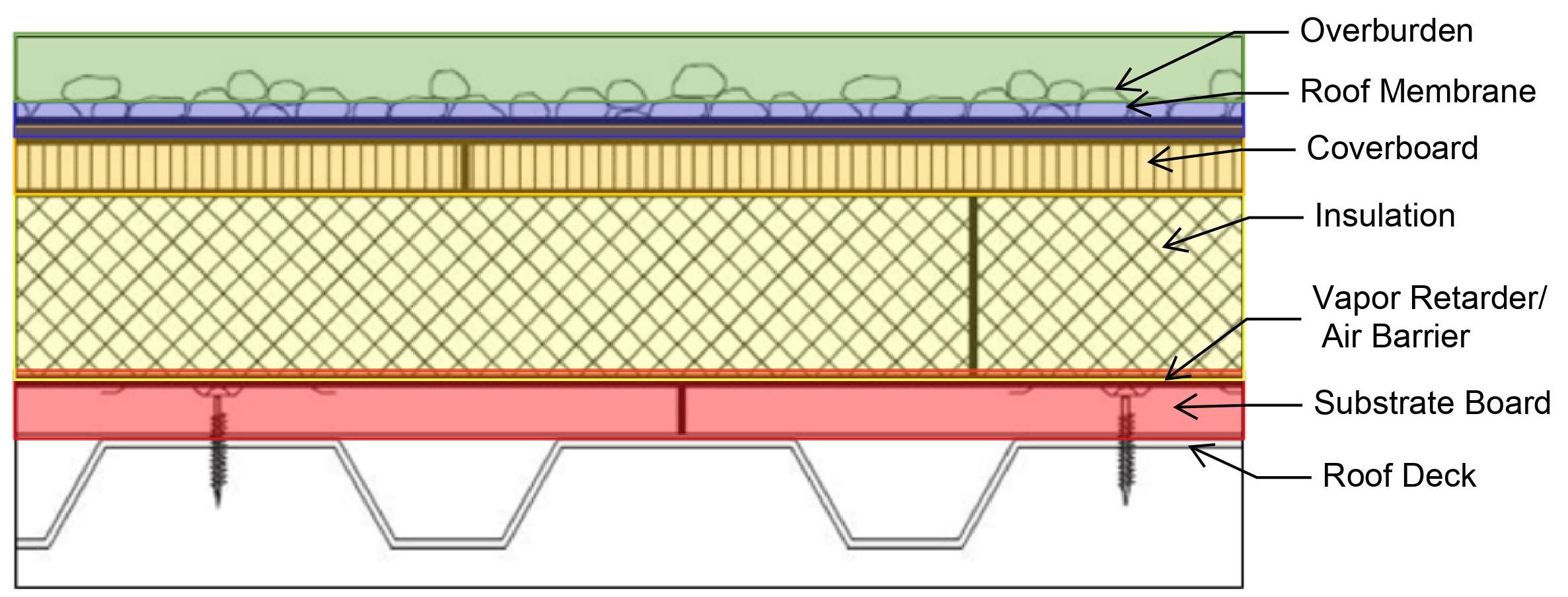
Basic roof components.
Roof Deck
Just as the foundation is the load-bearing portion of a building, roof decking forms the load-bearing portion of the roof system. Decking is designed to bear the weight of the entire roofing system, as well as snow, overburden, or equipment. The maximum load that the roof deck can withstand is most often limited by the overburden, particularly during reroofing of existing buildings.
There are three main roof deck types, classified by material: metal, wood, and concrete. Roof deck selection is influenced by the building construction type, building use, and regional trends. Each has their own implications to roof system selection including roof attachment methods and reaction to moisture.
Metal Decks
Metal decking accounts for approximately 45 percent of low-slope commercial roof decks due to its strength and speed of installation. Metal decks may be installed only as a metal deck or may also include a concrete slab. Additionally, metal decks may be vented or unvented. Vented decks are typically used for lightweight structural concrete systems to allow for drying of the concrete placed on top of the metal decking. For metal decks without concrete, the deck profile and gauge can impact the performance of the roofing system, including structural ratings, wind uplift resistance, and fire resistance.
For metal decks without concrete, which are most commonly unvented metal decks, roof systems are typically mechanically attached to the metal deck. Roof systems can be mechanically attached through all of the layers of insulation, or only the first layer of insulation with additional layers adhered. Ballasting roof materials is also an option, however, wind uplift and weight of specific ballasted assemblies should be verified. Another consideration for metal decks is the flute span capability of the materials placed directly on the metal deck. The concept of flute span capability is directly associated with the strength of the material being installed and its ability to handle the anticipated loads where the material is not supported by the top flange of the roof deck (that is, over the flute). This is directly related to thickness of materials, such as rigid insulation, perlite boards, or gypsum roof boards that may be placed directly on the deck.
While steel takes longer to degrade from moisture than other construction materials, steel is still susceptible to moisture intrusion. Moisture on the steel deck can cause corrosion, including rust, that if left untreated, can weaken the deck structure and require section replacement.
Wood Decks
Wood decks may be composed of plywood, oriented strand board (OSB), plank, panelized, or mass timber. Roughly 25 percent of roof decks are wood, a factor related to both regional construction preferences and the age of the building. Wood is a combustible and organic material, which are primary characteristics that need to be considered when designing low-slope roofing assemblies. Being an organic material, wood is susceptible to moisture so insulation placement and condensation potential are critical in the design. While it is common to have below-deck insulation in wood deck assemblies, the addition of insulation above deck may substantially reduce the condensation potential in assemblies where there is risk. Condensation, or trapped moisture on wood decks can rot the wood deck, which can lead to substantial wood deck replacement during reroofing.
Additional considerations are required to accommodate combustibility requirements. A material such as a fire resistant slip sheet may be required on the deck prior to installation of insulation, or the use of a fire rated insulation board with coated glass fiber facers that will meet a specific fire rating may be installed directly on the wood deck.
Roof systems are typically mechanically attached to wood decks. Where rigid insulation is used above deck, the first layer of insulation can be mechanically attached and subsequent layers can be adhered.
Concrete Decks
Concrete decks may be either structural or LWIC (lightweight insulating concrete). Structural concrete decks can be further divided into normal weight, lightweight structural, post-tensioned, and precast categories. While each of these are installed differently and have different structural properties, they are similar in moisture considerations and roof system attachment.
Concrete roof decks account for approximately 30 percent of roof decks. While concrete roof decks can be both mechanically attached and adhered, particular attention is needed when designing attachment to a concrete roof deck. Mechanical fastening is more labor intensive, and for structural concrete roof decks, X-ray or GPR is required so that the mechanical attachments do not penetrate the structural reinforcement. Adhered attachment methods are preferred for structural concrete decks. Ballasting roof materials is also an option, however, wind uplift of specific ballasted assemblies should be verified.
The inherent moisture in concrete decks is a concern. One of the main components in concrete is water, so the question of whether the concrete is ‘dry’ is often debated. A common misconception is that a concrete roof deck will be dry in 28 days, however, 28 days is the accepted time that concrete needs to obtain required compressive strength, not dryness. Additionally, as roof decks are exposed to the weather (rain, dewpoint condensation) during construction, water is reintroduced into the roof deck. The concern with a concrete deck that is not dry is that the inherent moisture in the deck is trapped within the vapor impermeable roofing assembly. The trapped moisture can lead to moisture accumulation, mold, and deterioration of roofing assemblies. For this reason, Class 1 vapor retarders installed on the deck level are recommended.
Trapped moisture within the concrete also has concerns over the lifespan on the roofing system. The repair of a concrete roof deck in a reroof scenario requires specialized contractors and equipment to properly repair the deteriorated locations. At locations of deterioration, the concrete is removed and new concrete is placed. While these repair methods are common, the concrete patches reintroduce moisture into the roof system.

Roof deck comparison chart.
Insulation
Rigid roof insulation is typically installed above the roof deck in most commercial assemblies. The most common insulation materials for commercial low slope roofs include polyisocyanurate (polyiso), expanded polystyrene (EPS), and extruded polystyrene (XPS). Other types such as mineral wool and vacuum insulated panels (VIP) are also available and installed in various roofing assemblies.
The selection of insulation should contrast among the various properties of the insulations; each of these types have their place in the market. Providing adequate insulation is critical in roofing assemblies for overall energy efficiency of the building. The higher the R-value, expressed per inch, the better the thermal performance of the insulation and its effectiveness at maintaining interior temperatures. One factor to consider for existing roofs where termination heights are limited, selecting a material with a higher R-value per inch can reduce the height of the insulation to help designers meet the height restrictions. Besides thermal resistance and a stable R-value, the insulation’s compatibility with adhesives, its component compatibility, water absorption, and compressive strength all need to be compared prior to selecting a material.
Polyiso has become the dominant insulation for commercial roofing, making up more than 70 percent of the market. Of the most common insulation types, polyiso offers the highest R-value per inch, meaning that polyiso does not require as much thickness as other types of rigid insulation to achieve the same insulation performance. Polyiso also offers good fire resistance as being a thermoset. Unlike polystyrene foams, it does not melt during a fire which can be hazardous for occupants and fire crews. Polyiso insulation is manufactured with a facer on each the top and bottom of the board. Two types of facers are available including glass fiber reinforced facers (GRF) and coated glass facers (CGF). GRF are made with organic fibers, and CGF are made with inorganic fibers; CGF further provides moisture protection and resistance to mold. Due to the facers, adhesives used in many adhered systems do not adversely affect polyiso, allowing it superior solvent compatibility when compared with polystyrene foams.
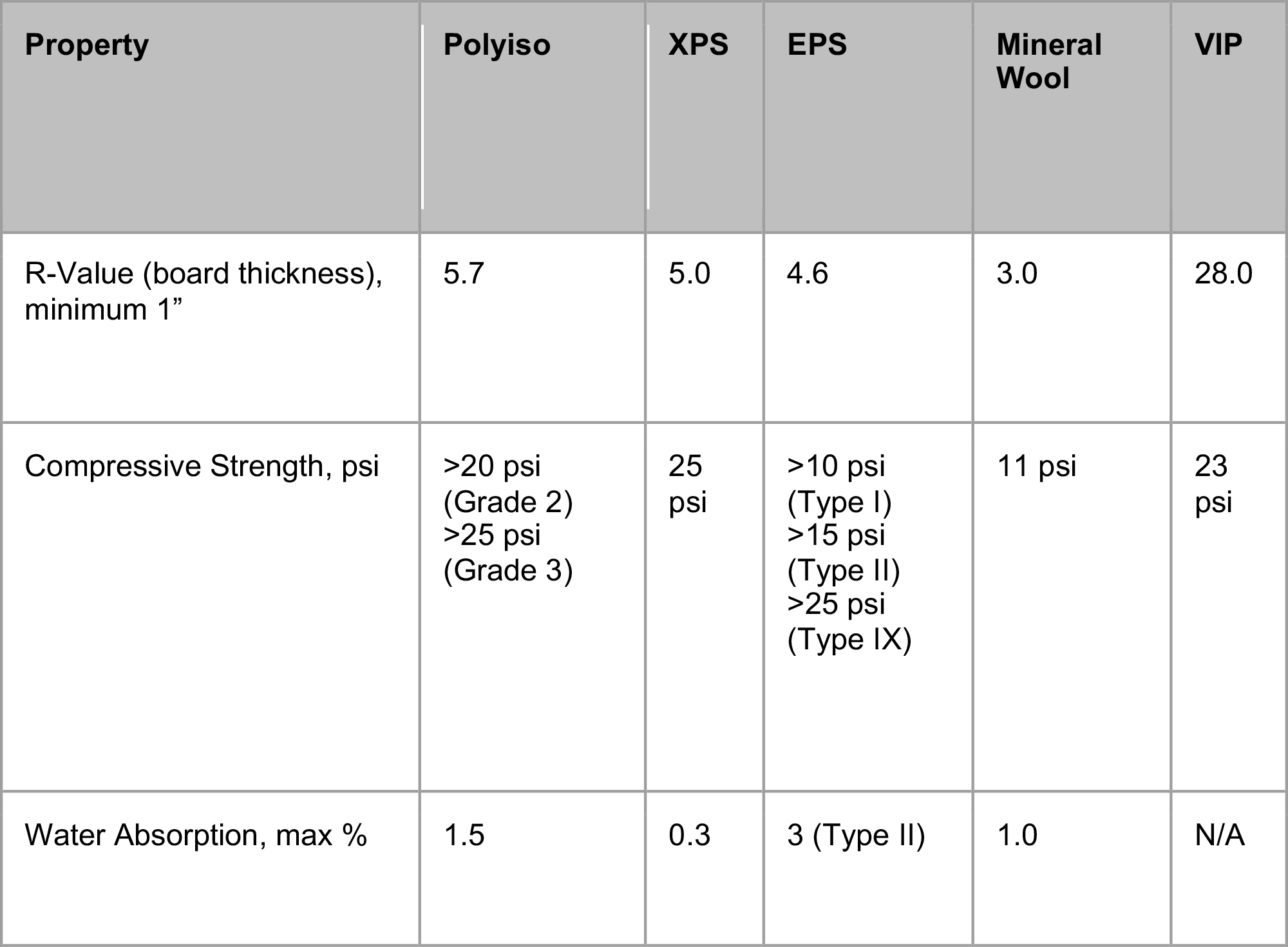
Insulation comparison chart.
Improper installation of the right insulation can impact overall roof performance. Insulation boards are required to be installed so that the joints are staggered and offset, and several layers of insulation should be installed rather than just one thick layer. Gaps between boards can decrease insulating ability by allowing thermal loss, as well as an increased condensation potential if air travels into and through the roof assembly. Air flowing between the boards also brings moisture, which if allowed to condense, can saturate the insulation boards. Wet insulation has an R-value of approximately zero, rendering wet insulation useless.
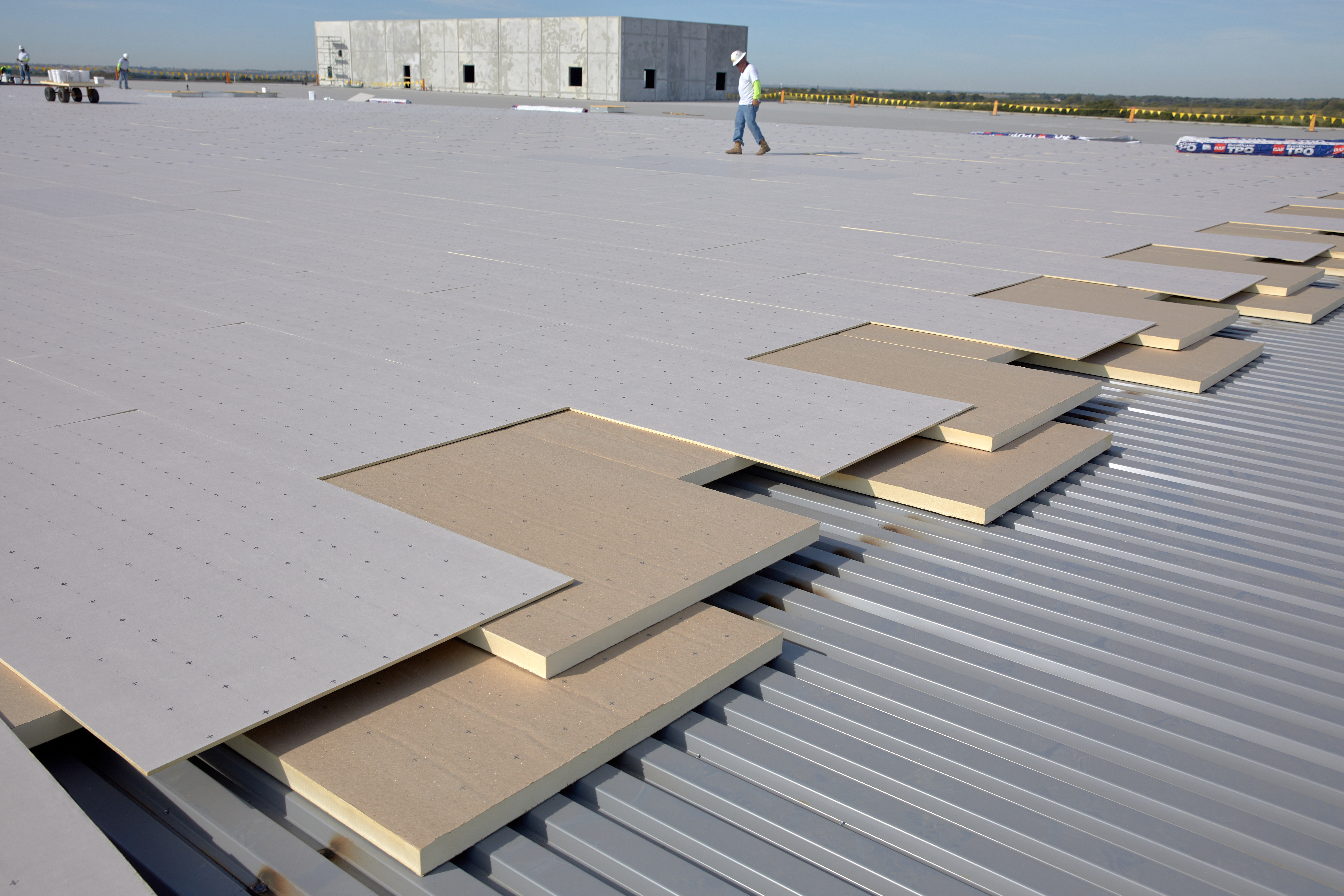
Staggering and offsetting insulation board joints on a steel deck.
Substrate Board/Roof Board and Vapor Retarder/Air Barrier
While not every roof assembly requires a dedicated vapor barrier or air barrier, it is important to know when one should be installed as well as recognize when it should not. Most often the roofing membrane functions as both the air barrier and the vapor barrier, however, controlling moisture is critical in roofing assemblies, and the use of a dedicated air or vapor barrier may assist in doing this. While both air barriers and vapor retarders can be used at the deck level to control air flow, only vapor retarders mitigate vapor transmission. A best practice is to install a vapor barrier on a concrete deck or over a building with high interior humidity where there is a higher potential for moisture vapor to enter into the roof assembly. For buildings with steel decks and spaces with high interior humidity, such as a natatorium, a substrate board installed on the steel deck will provide a sound substrate for the vapor retarder.
Incorrect placement of a vapor retarder can inadvertently trap moisture, and therefore, it can be a better design choice to not install a vapor retarder than to install it in the wrong configuration. The location and presence of a vapor retarder should be confirmed by hygrothermal analysis or a qualified design professional. Additionally, detailing for any air or vapor barrier is important as it must be continuous, across the roof and tied into the wall air or vapor barrier, without interruptions in order for it to function as intended.
Learn more about “Air Barriers, Vapor Retarders, and the roof in between”.
Coverboards
Coverboards are installed to prolong the life of the roof system, as they offer protection against fire, moisture, and heavy traffic. High density (HD) polyiso, glass mat, cementitious, and gypsum coverboards are the most common on the market today. Wood fiber and perlite are also available, although installed less frequently. Each has their advantages and considerations, including capability to resist hail and fire, and installation convenience. Coverboard selection also depends on the activities planned on the roof: for example, a higher compressive strength will be needed for solar or overburden installations, areas that experience larger hail, or high foot traffic zones. Coverboards also provide added protection against penetration, including tools dropped by service contractors. Coverboards not only increase the durability and resilience of a roof, but are considered a best practice to protect the entire roof assembly. Incorporating a coverboard into a roof assembly decreases overall lifecycle costs as replacement cycles are lengthened since the addition of the coverboard will mitigate damage from impact or foot traffic.
Coverboard selection may be influenced by ease of installation including weight of materials and ability to cut on-site. Wood fiber boards quickly became replaced in the market by newer technologies due to its heavyweight and the need for saws to cut. Most technologies only require the use of a utility knife. The weight of the boards also varies by material type. HD polyiso is very light and easy to cut, whereas glass mat gypsum is heavier, but must be used in areas where there is risk for larger hail stones.
Many insurance companies, including FM Global, may require a coverboard based on building location. FM Global has divided the contiguous US into three hail zones: Moderate Hail Zone, Severe Hail Zone, and Very Severe Hail. The hail zones are divided into the likelihood that a hail stone of a particular size is likely to occur in that zone. The selection of a coverboard will be determined by its ability to resist damage from hail of a particular size. For example, most coverboards available meet Severe Hail requirements, but only glass mat gypsum coverboards and plywood meet the restrictions of Very Severe Hail.
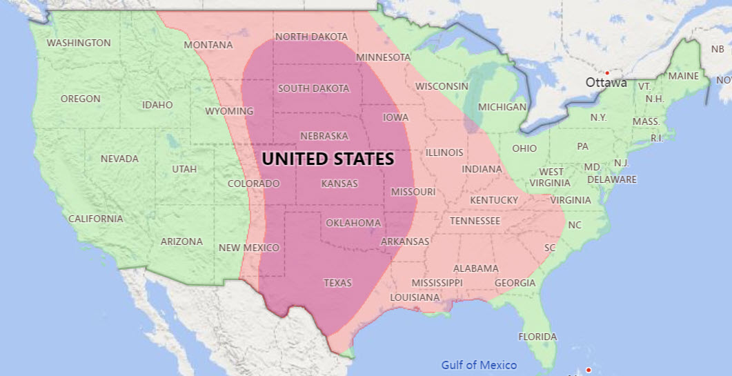
FM Global Hail zones where green is moderate hail (hail size ≤1.75”), pink is severe (hail size >1.75” and ≤2”), and dark pink is very severe hail (hail size >2”).
Each cover board has its place in the market. The roof assembly goals, including hail or resilience, should be reviewed in conjunction with the coverboard selection.
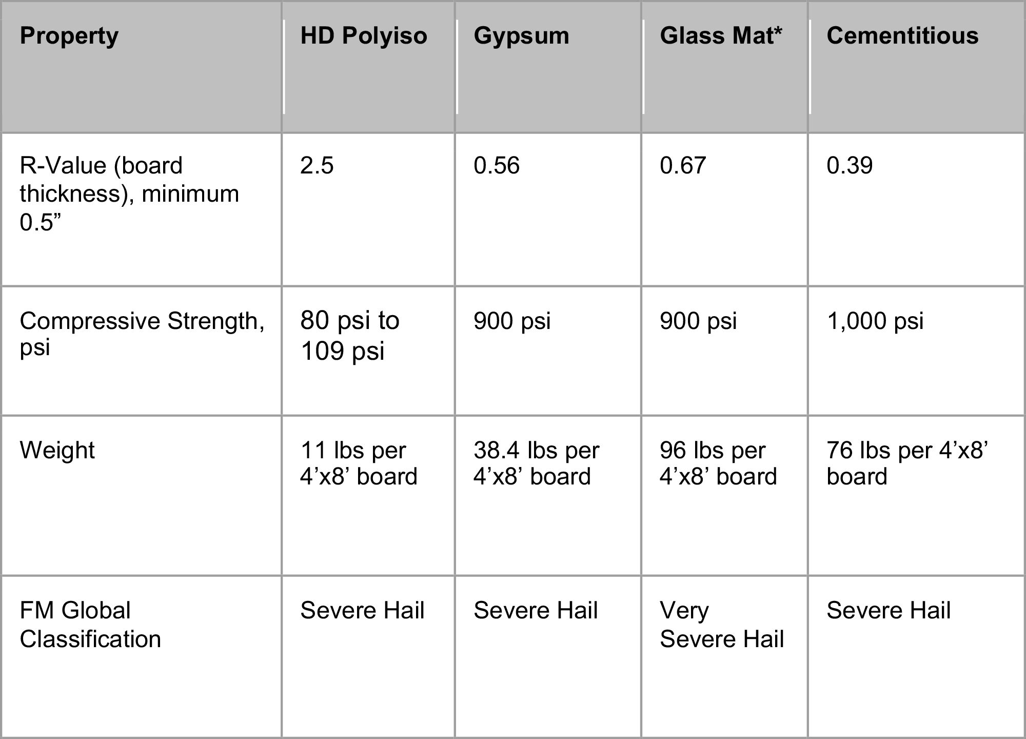
Coverboards compared at a glance. *Note that glass mat boards are typically ⅝ inches in thickness
Topping it Off: Selecting the Right Membrane and Attachment Method
Selection of the roof membrane, which acts as the waterproofing layer that protects the building, is critical. The membrane performance and roofing assembly configuration, including the location of the membrane in the assembly, must be considered. Selecting a membrane not adapted to the site specific challenges it will face can result in poor performance, costly repairs, or even replacement. Membrane performance is not only dependent on the associated roofing assembly materials, but also upon its design details and installation. Roof assembly selection and project specific design details down to the last termination and penetration detail should be provided to ensure the roof is installed in accordance with the contract documents.
Roofing Membrane Types
General roofing membrane types fall into these categories: asphaltic, single-ply, and liquid applied. Each roofing type has different chemical compositions, installation methods, and advantages; each of them has their place in the roofing industry.
Asphaltic roofing includes built-up roofing and modified bitumen. Both roofing types consist of several layers, or plies, of roofing, that are installed on the roof with various forms of asphalt.
Single-ply membranes are, as their name implies, a single layer of membrane roof material and are produced in rolls. Due to the nature of a single-ply roof, it can be rolled out more quickly than a traditional asphaltic system. However, due to the one layer, the membrane is not as robust as an asphaltic roof system with a granular surface. Single-ply membranes include EPDM, TPO, and PVC. The primary difference between the membranes is chemical composition, performance when exposed to chemicals at the roof surface, and treatment of the seams. Single-ply membranes are the most popular roofing membrane today due to their ease of installation and low cost compared to asphalt based materials. The chemical make-up of each of the membranes is different, and therefore, each of the membranes is preferable in different applications.
Liquid applied membranes are similar to a built-up roof where there are layers of liquid applied membrane and reinforcement installed directly on the roof. There are various chemical compositions available on the market.
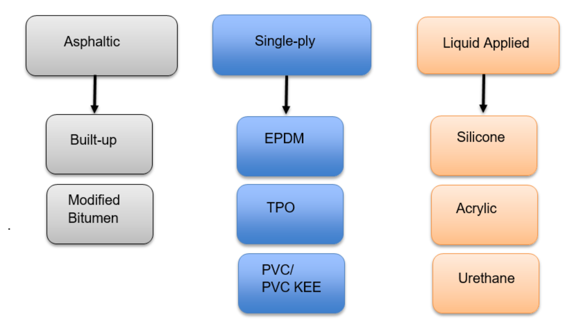
Roofing membrane types.
Built-up Roofing
As the original asphalt roof, built-up roofing dominated the low-slope roofing market for over 100 years but peaked in popularity during the 1970’s. Built-up roofing is labor intensive and requires special skills for installers, however, it is still installed today due to its robustness as a result of the many layers. Built-up roofing, or BUR, utilizes multiple layers of asphalt alternated with roofing ply sheets. Built-up roofs typically consist of four to five base plies of reinforcement and a cap ply where these layers are “built-up” across the roof deck. The asphalt is heated on the roof in a kettle, at temperatures upwards of 450 degrees Fahrenheit. Once the asphalt is melted, the plies are ‘mopped’ into place. After the plies are in place, an additional ply with UV protection is added on top of the base plies. The topmost layer, or cap ply, often consists of a ‘flood and gravel coat’ which is an additional layer of hot mopped asphalt with gravel cast into the melted asphalt. Gravel protects the asphalt from UV deterioration and also provides additional robustness to the base plies. One advantage of using hot asphalt is that it can be melted and installed in a wide range of temperatures, including very cold temperatures.
Today, BUR roofs have been largely replaced by modified bitumen roofs in part to the high labor and skill set required for these roofs. Additionally, some insurance companies do not allow for a hot kettle to be on the roof due to the fire hazard. The fumes of the melted asphalt can also be a concern in an existing building in a reroof scenario. However, BUR, with a completed thickness of 200 mils or more, is a robust roofing solution that is still used in many roof applications where robustness is a primary factor including at hospitals and schools.
Performance highlights:
- Redundancy to protect against moisture intrusion, damage (4-6 plies).
- Gravel surfacing provides excellent protection against damage and penetration.
- Low temperature installation.
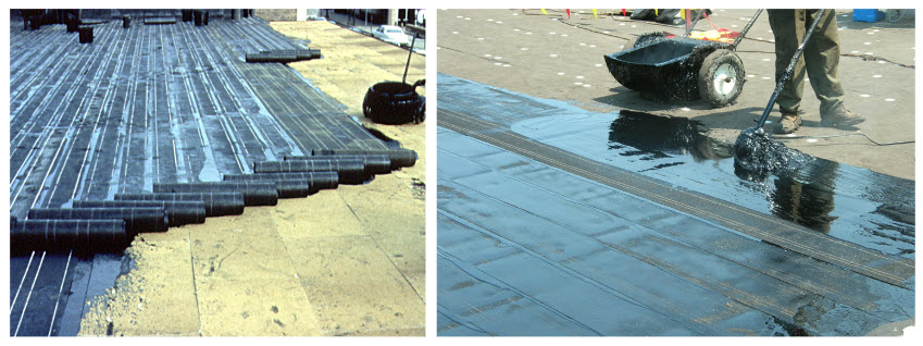
Modified bitumen installation, base plies being installed (left), hot mopping asphalt (right).
Modified Bitumen
Created in Europe in the 1960’s, modified bitumen is a modern day built-up roof that consists of the same asphalt plies, but instead of building the plies on the roof, they are produced in rolls in a factory. Modified bitumen roofs offer the same durable protection of a built-up roof with a faster and more consistent installation since the rolls are pre-manufactured offsite. Modified bitumen roofs have a base ply and a granulated cap sheet (called a two ply system), where the cap sheet has embedded granules that provide an excellent wearing surface. The multiple plies create a robust system where the completed thickness can be more than 200 mils.
Bitumen, another word for asphalt, is modified by two main polymers, hence the name modified bitumen. Modified bitumen roofs are either SBS (Styrene Butadiene Styrene), which is modified by bitumen rubber polymers or APP (Atactic Polypropylene) which is modified by plastic polymers. The modified bitumen is placed on reinforcement in the factory and manufactured into rolls or ‘sheets’. Due to the two polymers that modify the asphalt, the sheets behave slightly differently and can be installed in various methods. Synthetic rubber allows the SBS sheets to achieve greater elongation ratings than other asphaltic systems. SBS systems also have the widest range of application methods as they can be hot-mopped, cold-applied, torch applied, or self-adhered. APP is typically only torch applied. Both systems have several layers for redundancy, and the cap plies can be covered in granules of various colors, including white for increased reflectivity.
With the wide variety of installation method options, modified bitumen is a robust roofing solution that can be adapted for many applications. For existing buildings where fumes from hot mopping or a torch application may be a concern, cold-applied or self-adhered installation methods are alternatives. Additionally, there are available liquid flashings that can be installed with modified bitumen systems. Liquid flashings are ideal for odd shaped penetrations and areas that are difficult to flash due to a high number of penetrations in one location or if there is limited accessibility.
Performance highlights:
- Faster to install than BUR.
- Redundancy to protect against moisture intrusion, damage (2-3 plies).
- Available with highly reflective granules on the cap sheet for energy savings.
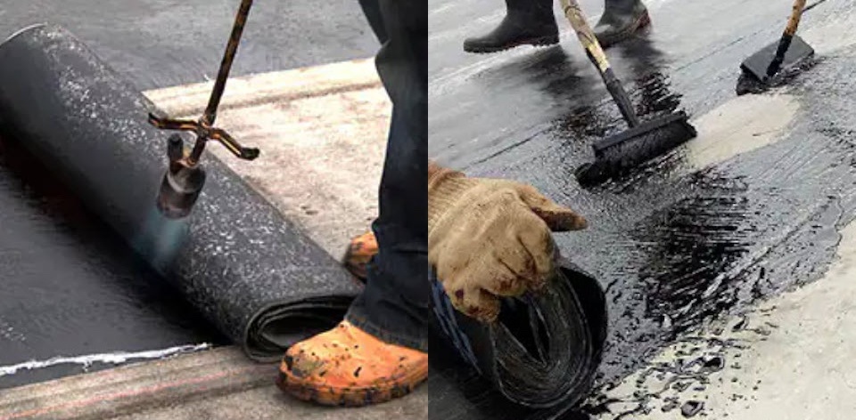
Modified bitumen torch applied (left) and cold applied (right).
EPDM (Ethylene Propylene Diene Monomer)
EPDM was first introduced to the automotive industry in the 1960’s and is often referred to as a rubber roof. EPDM quickly gained popularity due to its ease and speed of installation as it is manufactured in rolls that are shipped to the site and rolled onto the roof with no additional membrane layers required. Currently, EPDM roof installations account for approximately 15 percent of the commercial roofing market. EPDM is typically black in color due to its ingredient of carbon black. However, white EPDM is available often at an increased price and decreased UV resistance when compared to black EPDM.
EPDM is available in large sheets, which are flexible and bend easily at transitions making it easy to install. Seams between sheets must be glued or taped, which can lose adhesion over time, especially if not prepared properly during installation. Additionally, EPDM is prone to shrinkage over time, which can put stress on the glued or taped seams. EPDM has poor resistance to acids, greases, oils, and is incompatible with asphaltic products. Compatibility for any potential chemicals on the roof should always be confirmed.
EPDM is typically manufactured in thicknesses of 45 to 90 mils and is versatile in its attachment method as it can be mechanically attached, ballasted or adhered, which makes it ideal for a wide range of applications.
Performance highlights:
- Available in very large sheets.
- Very flexible and easy to bend at transitions.
- White EPDM is available but with added cost.
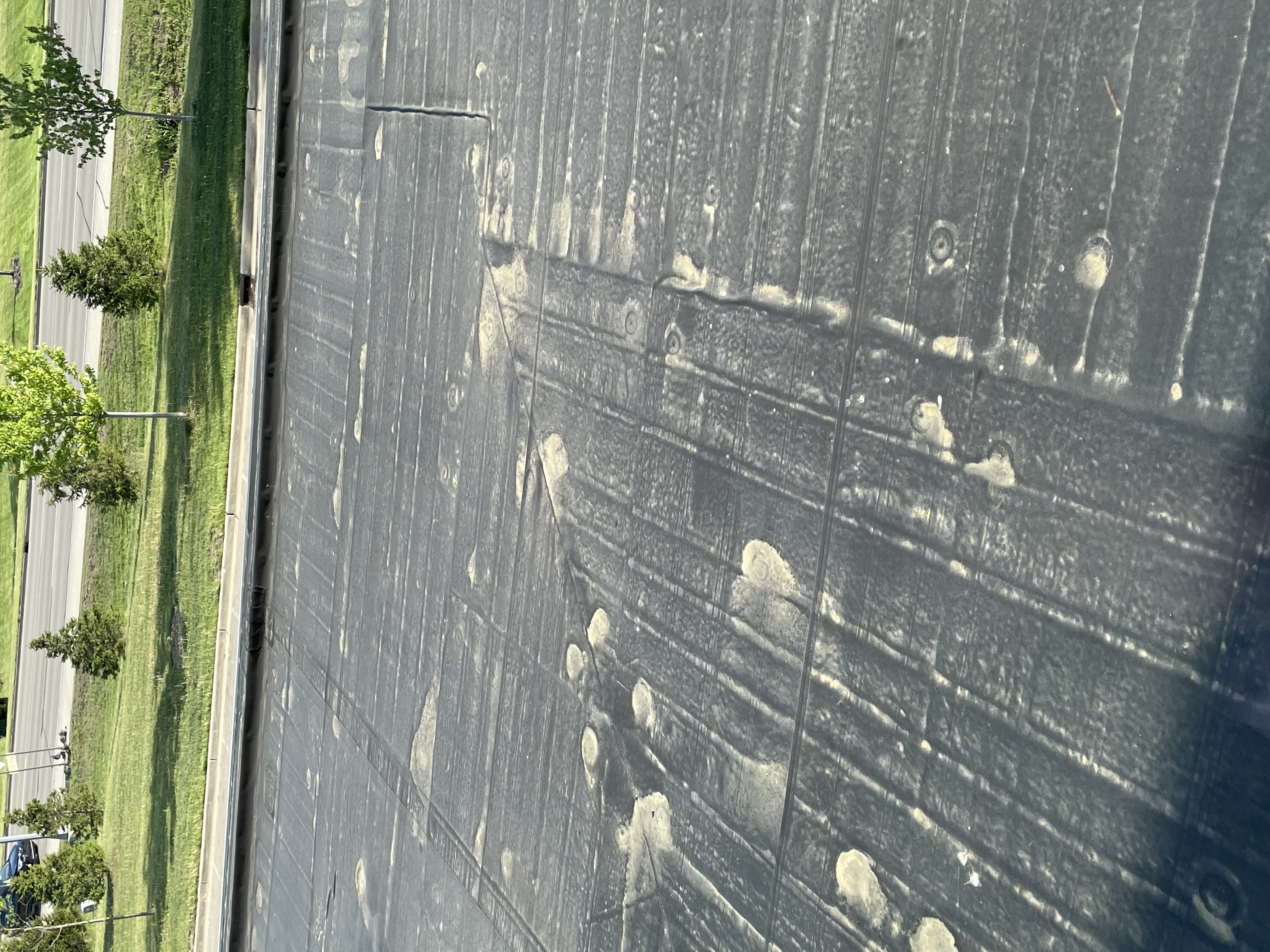
Black EPDM roof.
TPO (Thermoplastic Polyolefin)
TPO membranes were first introduced into the roofing market in the early 1980’s and were standardized with the creation of ASTM D 6878 in 2003. Currently, TPO has greater than 50 percent of the low-slope commercial roofing market share due to its speed and ease of installation.
TPO membranes consist of three main components: a UV resistant cap, a core (reinforcement scrim), and a base. These three components are fused together during the manufacturing process. The cap and the core consist of similar components, but the cap contains UV stabilizers, which provide long-term weathering resistance. TPO is inherently flexible and dimensionally stable over time. Due to its chemical composition, TPO is naturally fungal resistant and has generally good resistance to chemicals. However, acids, greases, and oils should be avoided. Compatibility for any potential chemicals on the roof should always be confirmed.
TPO is manufactured in rolls that are shipped to the site and rolled onto the roof with no additional membrane layers required. After the membrane is rolled out onto the roof, the seams are heat welded together. The seam becomes monolithic and is the strongest component of the roof. TPO membranes are typically white in color, but can be manufactured in a range of standard and custom colors, including various reflective colors other than just white. TPO is typically manufactured in thicknesses of 45 mil, 60 mil, and 80 mils and they can be mechanically attached, adhered, ballasted, and induction welded. The wide range of thicknesses and installation methods make TPO a versatile choice for a wide range of applications.
Performance highlights:
- Strong, heat-welded seams.
- Inherently flexible, contains no plasticizers.
- Will not gray over time and has no fungal growth in warm climates.
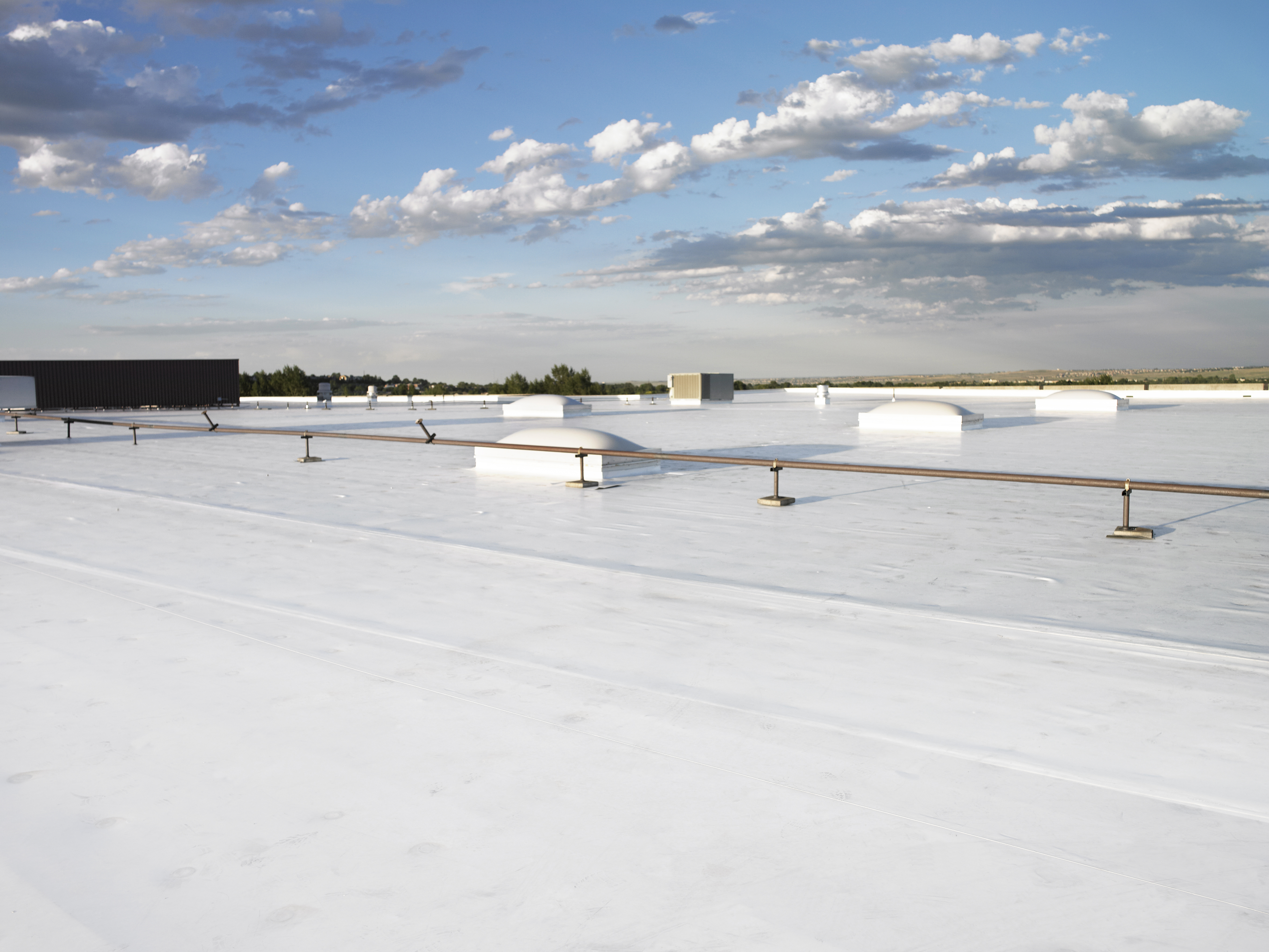
Completed TPO Roof.
PVC (Polyvinyl Chloride)
PVC roofing was created in Germany in the 1960’s and was subsequently introduced to the US in the 1970’s. This single-ply membrane is flexible which allows for easier detailing. PVC also offers increased chemical resistance compared to EPDM and TPO. PVC has a steady market share due to its increased resistance to oil, grease, and chemicals.
Similar to TPO, PVC membranes consist of three main components: a UV resistant cap, a core (reinforcement scrim), and a base. These three components are fused together during the manufacturing process into rolls. The rolls that are shipped to the site and rolled onto the roof with no additional membrane layers required. After the membrane is rolled out onto the roof, the seams are heat welded together. The seam becomes a monolithic component of the two seams and is the strongest component of the roof. PVC membranes are typically white in color, but can be manufactured in a range of standard and custom colors, including various reflective membranes other than just white. PVC is typically manufactured in thicknesses of 50 mil, 60 mil, and 80 mil and they can be mechanically attached, adhered, ballasted, and induction welded.
PVC membranes consist of a liquid plasticizer that enables the membrane to become flexible. Over time, the liquid plasticizer can leach from the membrane and cause the membrane to become rigid again, allowing the membrane to crack under stress or movement. While this was a concern with earlier PVC membranes, often the plasticizer does not completely leach from the membrane prior to the end of the expected useful life of modern membranes. However, in extreme climates, this may be a design consideration. PVC is incompatible with asphaltic products which cause the plasticizers to leach out. As with any roofing membrane, compatibility for any potential chemicals on the roof should always be confirmed. Over time algae and mildew may grow on the membrane surface largely due to the migration of the liquid plasticizers, which can impact reflectivity.
Performance Highlights:
- Excellent resistance to oil and grease.
- Very flexible during installation, good for detailing.
- Reflective colors available.
PVC KEE is a variation of a PVC membrane that includes a KEE solid plasticizer. KEE (Ketone Ethylene Ester) enhances the membrane so that it is more resistant to UV degradation. KEE is a solid plasticizer that does not leach from the membrane over time, and keeps the membrane inherently flexible. PVC KEE also has best in class resistance to chemicals including jet fuel, oils, and greases, and is ideal for restaurant or airport roofing applications.
Performance Highlights:
- Better long-term weathering.
- Best in class resistance to oil and grease.
- Remains flexible over lifecycle.
Completed PVC roof.
Liquid Applied
Liquid membrane roofing was developed in Europe in the 1980’s. These roofing systems are manufactured in various chemical compositions, including silicone, acrylic, and urethane. Liquid systems are modern built-up roofs where layers of liquid membrane and reinforcement are installed on the roof. Typically a base coat is installed, then a layer of reinforcing fabric is installed, and then a top coat. Depending on the formulation, liquid roofs can be installed by brush, airless sprayer, or roller. Completed thicknesses will vary by product, but can be more than 60 mils depending on the system.
Liquid applied systems offer superior results for complicated flashing and transition details and places that are difficult to access as they are self-terminating and seamless. Liquid membranes are available in reflective white as well as custom colors. Liquid applied membranes are sensitive to extreme temperatures, which can influence both installation and cure times. Roof coatings, which are generally liquid applied membranes without the reinforcement, are ideal for installing on top of an existing roof in overall fair condition without trapped moisture. This will extend the service life of the roof.
Performance Highlights:
- Liquid systems cure very quickly.
- Great solution for difficult penetration details.
- Various formulations have good resistance to oil and grease.
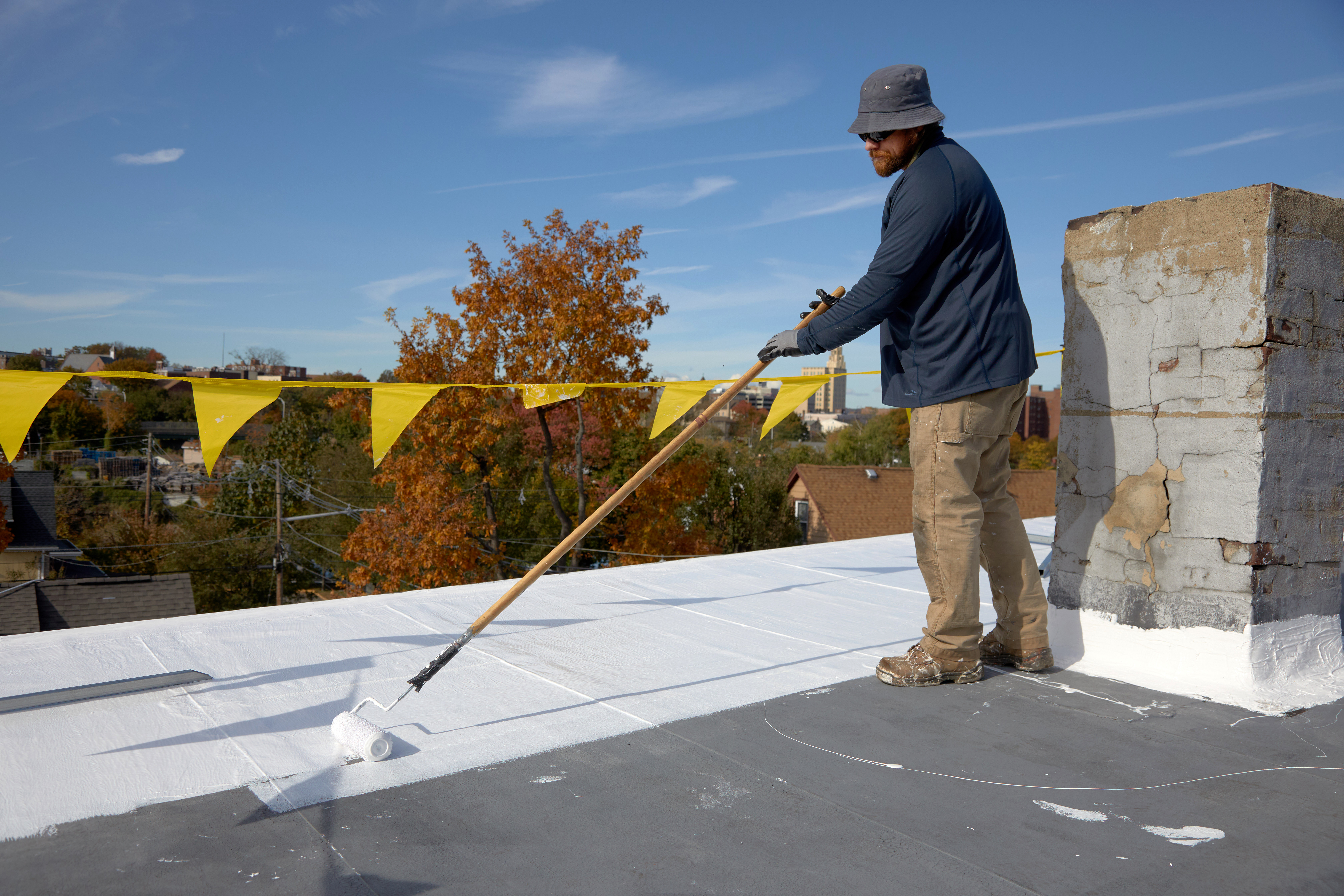
Liquid membrane roof installation in progress.
Membrane Color
Roof color can have a significant impact on the performance of the system and also on the roof surface temperatures; reflective roof membranes can lower the ambient roof temperature. EPDM membranes are traditionally dark in color and TPO, PVC, and liquid roof membranes are typically white or light in color. BUR and modified bitumen roofs can have light colored granules on the cap sheet which can increase reflectivity of a roof’s surface. Two roof surface temperatures, differing only by color, can vary by as much as 60F in the summer heat. Dark colored roofs can reach up to 150F, whereas white or reflective roofing colors can have significantly lower surface temperatures. Using a lighter colored roof can decrease the urban heat island effect in cities, and also may decrease the amount of heat that is able to radiate into a building’s interior. The more heat gain that a roof assembly absorbs, the warmer the interior temperature will be. In the summer, while the heat gain is offset by HVAC systems, the warmer the interior temperature causes the systems to have to run longer, which can increase energy use, and potentially raise energy bills.
For roofs where there is overburden, such as solar panel installations, light colored or reflective roof membranes can lower the ambient roof temperature which allows the panels to function more efficiently. The temperature of a PV panel can significantly impact how much electricity the panel produces; as panels get hotter, they produce less power. According to an article published by GAF, “It is estimated that the efficiency of a PV panel can be up to 13 percent higher when installed over a highly reflective membrane compared to a dark membrane with low reflectance. Also, the use of bifacial PV panels over reflective roof membranes can increase the efficiency by 20-35 percent, as they take advantage of the reflected light.”
Reflective roofs, or cool roofs, are also being installed in many locations to meet local green building standards. Many municipalities have adopted Codes that require new or replacement roofs to meet a minimum Solar Reflective Index (SRI), an indicator of the ability of a roof surface to return solar energy to the atmosphere. The Cool Roof Rating Council has a directory of roof products with SRI values listed for reference.
Membrane Attachment Methods
There are two broad categories of roof attachment; mechanically attached via use of fasteners, and adhered. The attachment method will vary depending on the deck type, membrane type, and project specific requirements such as energy efficiency, fume tolerance, and fire hazards.
Selection of attachment methods should be reviewed for ease of installation in the short-term and energy efficiency over the long-term. Energy efficiency from the roof assembly can be directly related to thermal bridging, which occurs when components allow for heat transfer through the roof assembly. Loss of internal temperatures means that the mechanical equipment will have to work harder to maintain the desired set points. Thermal bridging has the potential to occur at gaps or discontinuities between materials, such as at fasteners in a mechanically attached single-ply system. Particularly where the fasteners penetrate the entire assembly from the membrane through the insulation and into the deck, the fasteners provide a direct thermal path from the exterior to the interior.
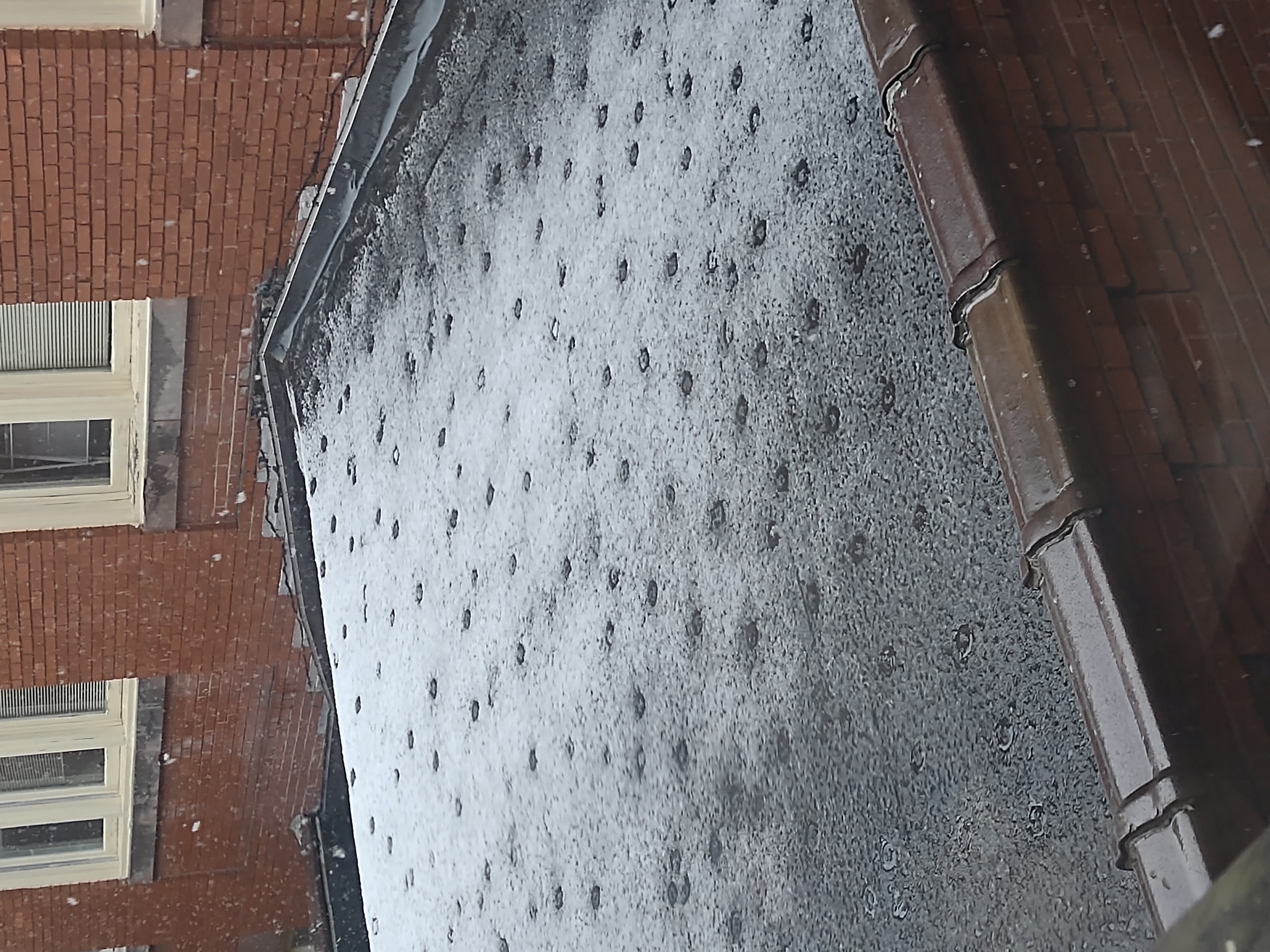
A mechanically attached single-ply system. Thermal bridging from the fasteners is melting the snow on the roof.
Mechanically Attached Systems
Mechanically attached systems are generally referring to single-ply systems as these membrane types often use fasteners to install both the insulation layers and the membrane. The fasteners must be continuous through each layer and into the structural roof deck for securement. The number of fasteners will depend on project specific requirements, but typically for a mechanically attached system, there is a minimum of six fasteners per 4’x8’ insulation board, and additional fasteners for membrane attachment. This can lead to a substantial number of fasteners penetrating and creating thermal bridges within the roof assembly. It is important to note that most systems require the first layer of insulation to be attached with fasteners, even if the specified system is to be adhered. However, by burying the fasteners in the system, and adding adhered layers of insulation and membrane on top of the mechanically attached insulation layer, the interior air loss and thermal bridging is significantly reduced.
Mechanically attached single-ply systems are also subject to billowing in high wind events. Billowing, or fluttering, of a membrane is when wind causes a negative pressure by pulling interior air into the roof assembly creating uplift force on the roof assembly. Although this is an acceptable behavior of single-ply membranes, over time, it can cause stress and fatigue on the mechanical attachments and membrane. Interior air that is pulled into the roof assembly equates to energy loss since often the temperature controlled air may warm or cool based on the temperature of the membrane.
It should be noted that mechanically attached single-ply systems are commonplace in the market and have had many years of successful installations. These systems are also able to achieve high wind uplift ratings due to the direct attachment to the roof deck and have no fumes associated with the installation.
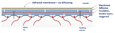
Adhered system where only the first layer of insulation is mechanically attached, significantly reduces interior air loss and thermal bridging.
Asphaltic systems can be installed utilizing fasteners, however, these fasteners are only installed to secure the insulation to the deck. While there are significantly less fasteners used in asphaltic systems than in mechanically attached single-ply systems, there is still potential to reduce thermal bridging of the fasteners. Fasteners can be installed only in the first layer of insulation and then each subsequent layer of insulation can be installed with adhesives. Similarly, since asphaltic membranes are not installed with fasteners, they are not subject to billowing like single-ply membranes are, and generally have reduced air movement through the roof assembly.
Adhered Systems
Systems that use adhesives to secure the roof assembly and do not use fasteners, greatly reduce thermal bridging by eliminating the path from the interior of the roofing assembly to the exterior. Adhering also prevents billowing of the membrane, by mitigating the interior air that can be brought into the roof assembly.
Asphaltic based membranes use asphalt to adhere the roof assembly. BUR roofs use several layers of plies and asphalt to form the roof surface. Modified bitumen roofs can be installed several different ways, including using a torch to melt the asphalt plies or by using a cold applied adhesive. The multiple asphalt plies in either system form a robust roofing system that is not penetrable to air or the effects of billowing. Asphalt, and particularly hot (torched-applied or hot mopped) asphalt, can have strong fumes. On an occupied building during a reroof, or a building in close proximity to other buildings, the use of asphalt may not be preferable since HVAC intakes may transport asphalt fumes into the building. Many insurance companies and jurisdictions do not allow the use of torches or hot kettles on the roof due to the fire hazard of open flames. Cold applied modified bitumen applications are an alternative that use an asphaltic based adhesive that is rolled onto the substrate prior to installation of the membrane. Cold applied applications offer the same modified bitumen wearing surface, but with fewer fumes than a traditional torch applied or hot mopped application. Modified bitumen roofs are excellent for mitigating air movement as the multiple layers are impermeable to air, and therefore are not subject to billowing like mechanically fastened single-ply systems.
Single-ply membranes tolerate a wide variety of attachment methods and are able to be both adhered and mechanically attached. The types of adhesives can vary from melted asphalt (with fleece-backed membranes) to various types of commercial adhesives manufactured for specific single-ply membrane types. Although product specific, single-ply adhesives release fewer hazardous fumes during installation, in contrast to those by asphalt based products. These adhesives do not require heating or torching for application and generally come in pails or canisters and can be installed with a roller or a spray attachment. Single-ply adhesives are generally less messy and can be quicker to install than traditional asphaltic based products.
Another adhered option for both single-ply and asphaltic cap sheets is a self-adhered option. For these membranes, an adhesive is factory-applied onto the back of the membrane and a release liner is removed on-site to expose the adhesive once ready for installation. Self-adhered membranes function similarly to a membrane installed with an adhesive, which results in the membrane not billowing on the roof. Self-adhered membranes also have little to no fumes associated with the installation. There is a waste factor to consider, as the release liner will require disposal.
Induction Welded Systems
Induction welded fasteners are another type of roof attachment that is installed frequently in the single-ply roofing market. By definition this is a mechanical attachment method, but it has many of the features of adhered systems. The technique fastens TPO and PVC membranes to the substrate below using a microprocessor-controlled induction welding machine. The thermoplastic roof membrane is welded directly to specially coated fastening plates used to attach the insulation. The combined insulation and membrane fasteners resist wind uplift forces, so that wind loads are more uniformly distributed versus a conventionally attached system. Thermal bridging is also reduced, compared to traditional mechanically attached membrane systems as there are less fasteners required for this installation. There are no application temperature restrictions and there are no fumes or fire hazards associated with the installation.
Ballasted Roof Systems
Ballasted roof systems are where the membrane is not attached to the roof, it is held down by overburden placed on the membrane. Many EPDM roof systems were historically ballasted with gravel such as a smooth river rock stone. Modern day ballasted roofs consist of pavers or amenity spaces and can be installed over most single-ply and asphaltic membranes. The challenge with ballasted systems are the weight of the ballast and the difficulty to find leaks as the ballast must be removed for investigation and repair.
Many insurance companies and municipalities limit the size or prohibit gravel ballast since it can become projectiles during a wind event. Ballasted systems can also present challenges on existing buildings in re-roofing scenarios as more recent provisions increase requirements that older buildings may not be able to accommodate due to weight restrictions or lack or parapet walls.
Overburden Assemblies
Often unused space on the buildings, roof space is more commonly being utilized. Roofs can be a space to integrate solar for renewable energy, rainwater management strategies, rooftop agriculture, and amenity space. While design of the overburden system is important, selection of the roof membrane, the waterproofing layer that protects the building, is critical for the success of the overburden installation. Two main considerations are membrane performance (including color, thickness, and attachment) and roof assembly configuration, including location of the membrane in the assembly. The improper selection of membrane can result in water infiltration into the building, costly repairs, or even replacement. Incorporation of a leak detection system into the roof assembly may also be beneficial. Special considerations to the type of insulation and the presence of a cover board should be explored. Most importantly, the roof system should be designed to have an equivalent or longer lifespan than that of the overburden systems. When there are leaks, the overburden will require removal which can be costly and damaging to the overburden systems.
Special considerations are needed for the roof assembly when overburden is present. Read this article on Overburden for further information.
Conclusion
Each Roof is Unique
Each roof is unique. A building’s interior use, its climate, and planned rooftop use all will impact roof design. The roof assembly itself can have a profound impact on the energy efficiency and operation of a facility. While its main objective is to mitigate water entry into the building, appropriate quantities of insulation, and air and vapor control can affect how the roof functions over time. A well-designed roof assembly includes consideration of all components: from roof deck, insulation, and coverboard to attachment method and membrane. In addition, proper detailing and integration of the roof membrane, as well as the roof installation are paramount to the overall success and longevity of the roof system.
Kristin Westover PE, is part of the Building and Roofing Science Team where she works with designers on all types of low-slope roofing projects to review project design considerations so designers can make informed roof assembly decisions.