Introduction to Building Science
Unveiling what they don’t teach in school and designing to avoid performance thieves in the field
Sponsored by GAF | Siplast | By Andrea Wagner Watts and Elizabeth J. Grant, PhD, AIA
Copyright 2018 From Integrating Building Performance with Design by Elizabeth J. Grant. Reproduced by permission of Taylor and Francis Group, LLC, a division of Informa plc.
During its life, a building will face multiple challenges from its environment. Understanding the science behind design best practice can help a structure last longer, perform better, and avoid unintended consequences.
Defining Building Science
The Whole Building Design Guide defines building science as: “… a field of knowledge that draws upon physics, chemistry, engineering, architecture, and the life sciences. Understanding the physical behavior of the building as a system and how this impacts energy efficiency, durability, comfort and indoor air quality is essential to innovating high-performance buildings.”.1 In practice, building science applies what is known about physics, chemistry, and other scientific disciplines to how buildings are designed and built.
As an example, the use of building science in the design of a wall assembly may touch on concepts from material science such as the physical and chemical properties of materials like brick, insulation, and gypsum, and how those elements interact with moisture and heat. The laws of thermodynamics will be invoked to deal with heat transfer and pressure dynamics. Mechanical engineering principles are mustered to weigh the impacts of airflow and equipment that generates heat, cools air, and produces or removes moisture. Human health and biology are factors with respect to analyzing impacts of indoor air quality and the potential for mold growth within the assembly and the building as a whole. Added to all of this is a sound foundation of architecture and construction including best design practices, an understanding of the common and necessary construction techniques, and an appreciation of how the installation of materials is sequenced.
Building science is, at its core, aimed at seeing a building reach its full performance potential. In 1986, The Building Systems Integration Handbook2 gave voice to the idea of building performance, writing that “fundamentally, performance is the measurement of achievement against intention.” The authors introduced a set of criteria against which to measure the ability of a structure to match design intent based on a building’s performance. The building enclosure is not only aesthetic; its primary purpose is as an environmental separator: “It has to keep the outside out and the inside in. To do this the wall assembly has to control rain, air, vapor, and heat.”3
From the section on “Integration for Performance” by Hartkopf, Loftness, and Mill, The American Institute of Architects (AIA) defined six building performance mandates: spatial performance, thermal performance, air quality, acoustical performance, visual performance, and building integrity. Four of the six mandates can be classified under the heading of building science: thermal performance, air quality, acoustical performance and building integrity. Incorporating building science as an essential aspect of architectural design ensures that buildings are not only visually appealing but also functional.
In this introduction to building science, the principles of thermal performance, air quality, and building integrity are the focus. These elements hinge on the interaction of the materials, assemblies, and their design configurations in the building. The ultimate goal is to establish achievable performance expectations where enclosures perform as intended and they continue to perform through the project lifecycle. The durability aspects of enclosure design, including the roof assembly and how it relates to energy performance, will specifically be discussed. Rather than viewing the elements of a building as a collection of individual and unrelated components, ensuring continuity and performance of the building enclosure requires a systems perspective. Buildings have become increasingly complex systems, comprising many individual materials that must come together, stay together, and work together to avoid risks, both in the long and short term.
A Building’s Function and its Opposing Forces
It is an inescapable truth that natural forces are always at work on buildings. The fundamentals of building science have a foundation in the Second Law of Thermodynamics:
- Heat flows from warm to cold;
- Moisture flows from warm to cold;
- Moisture flows from wet to dry; and
- Air flows from areas of higher pressures to ones of lower pressures;
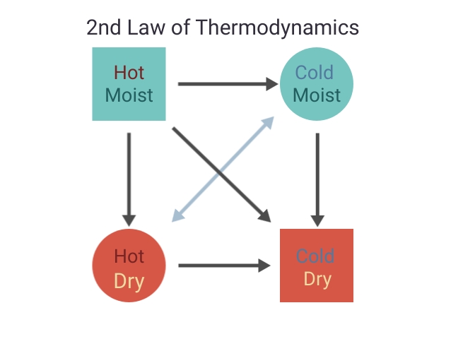
Figure courtesy of GAF|Siplast
Diagram of how the law of thermodynamics drives interaction between moist, dry, hot, and cold air.
A bonus fundamental property is that gravity always acts down. The Second Law states that energy, air, and moisture are exchanged between two systems until a state of equilibrium or balance is achieved. However, that is not necessarily the goal for a building enclosure. For example, it is not ideal to have both the interior and exterior environment hot and humid during a Florida summer. Keeping the building performing as designed often means controlling these forces. This control comes by way of control layers.
“Control layer” is the term used for the parts of the building enclosure that are designed to resist, regulate, or prevent external elements from moving uncontrolled through a structure. There are four main control layers in a building: they address liquid water, air, heat, and water vapor. Whether the control layer completely stops the movement of the elements or slows down the movement depends on the materials used. The selection of materials for each of the control layers and the location of each control layer is based on the needs of the building. In essence, the four control layers can be loosely split into two main categories: those that manage moisture and those that manage energy efficiency. Moisture management focuses on preventing liquid water, water vapor, and condensation from negatively impacting the building. Managing thermal performance or energy efficiency relies on controlling the movement of air and heat through the building enclosure.
Some control layer materials perform more than one function, and all of the control layers need to work together to achieve maximum effectiveness.
Continuity of control layers
The enclosure is better defined as a combination of control layers assembled and joined together in a system, providing a continuous boundary between conditioned and unconditioned space. Control layers are more accurately viewed as interconnected systems and assemblies instead of a single product or material. Due to the innate relationship between the building enclosure and building performance, it is critical to design for performance early in the architectural design process.
The four key control layers (water, air, thermal, and vapor) should generally be continuous across all six sides of the building enclosure. ASTM E2947 defines the term “building enclosure,” frequently used interchangeably with “building envelope,” to “refer collectively to materials, components, systems, and assemblies intended to provide shelter and environmental separation between interior and exterior, or between two or more environmentally distinct interior spaces in a building or structure.” One helpful tool to design and communicate the intent of the critical components and functions of the building enclosure is called the “pen test.” The “pen test” involves tracing each of the control layers around the building enclosure to ensure continuity. The premise is that if one has to lift one’s pen, that indicates a break in a control layer. It is relatively easy in theory, but it can get complicated at interfaces, penetrations, and transitions as is shown in Figure 3. For this reason, the pen test should be performed not only on the plans and elevations, but on the interface detail drawings where multiple materials and trades intersect. Once the control layers are defined, all materials that are used to complete the control layers in each detail should be explicitly called out and not simply shown on shop drawings as being “by others.”
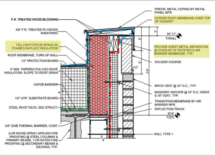
Figure courtesy of GAF/Siplast
The “pen test” is easy in theory, but it can get complicated at interfaces, penetrations, and transitions.
Moisture Management
Managing moisture involves multiple strategies to successfully combat bulk water, condensation, and water vapor. The first line of defense is to drain the water by draining and directing bulk water away from enclosure. This includes minimizing locations where water can sit for extended periods while working its way through weaknesses in the assembly, such as at joints or through capillary action in porous materials. The second strategy is to avoid allowing building materials to fall below the dew point temperature, defined as the temperature at which liquid air condenses out of an air sample. The more water is in the air (higher absolute humidity), the higher its dew point temperature. As materials cool, they become prone to moisture condensing on their surfaces because the air temperature on the surface dropped below the dewpoint of the higher temperature surrounding air. The key here is to keep materials above the dew point temperature of the air with which they interact. The final moisture management step is to manage diffusion. Diffusion is the process of moisture moving through materials themselves, not through interfaces; it allows for moisture to move through an assembly in at least one direction based on a material’s permeance. The process of diffusion is slow and should be the last strategy implemented for moisture (vapor only, not bulk water).
Case Study
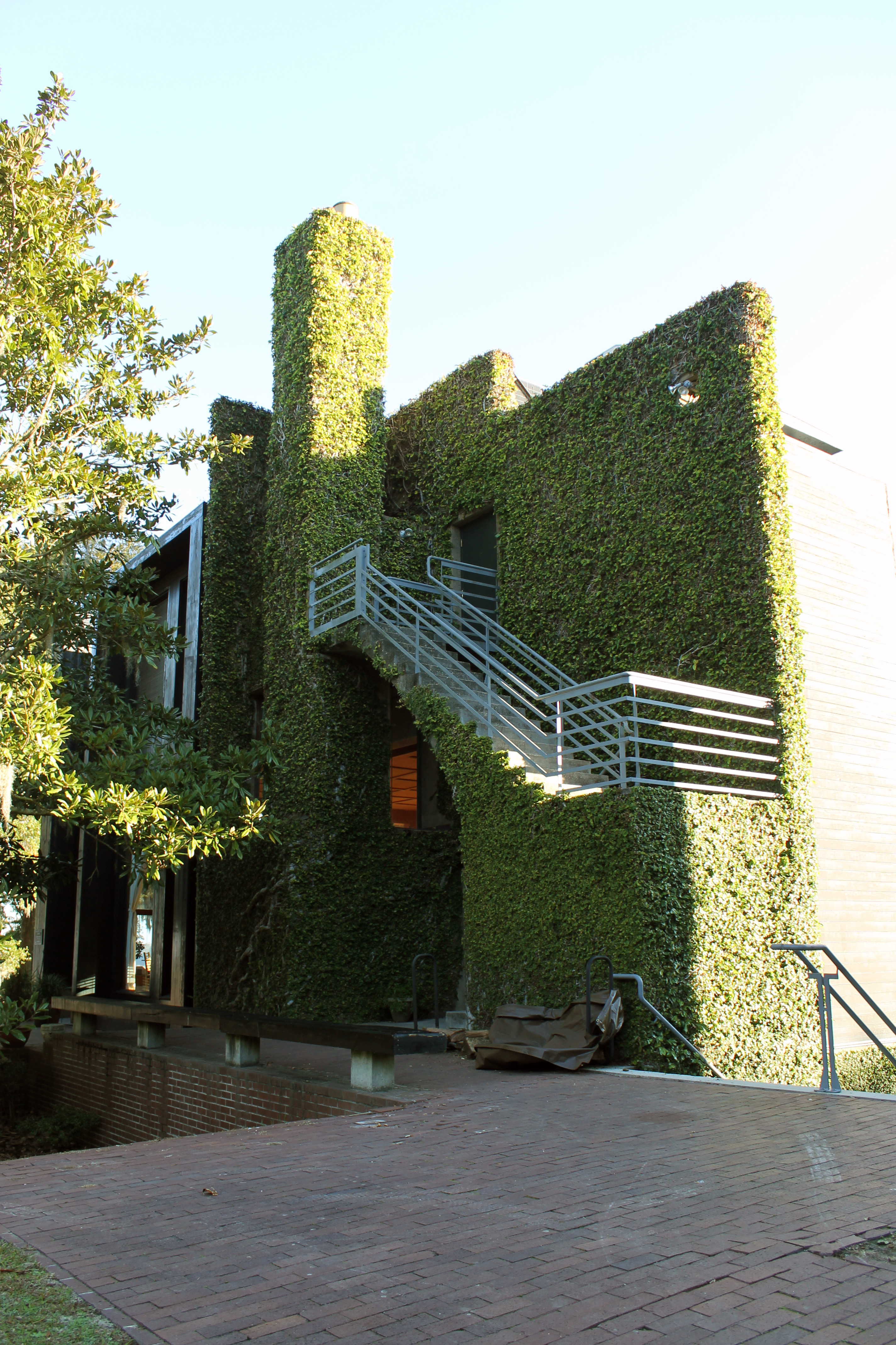
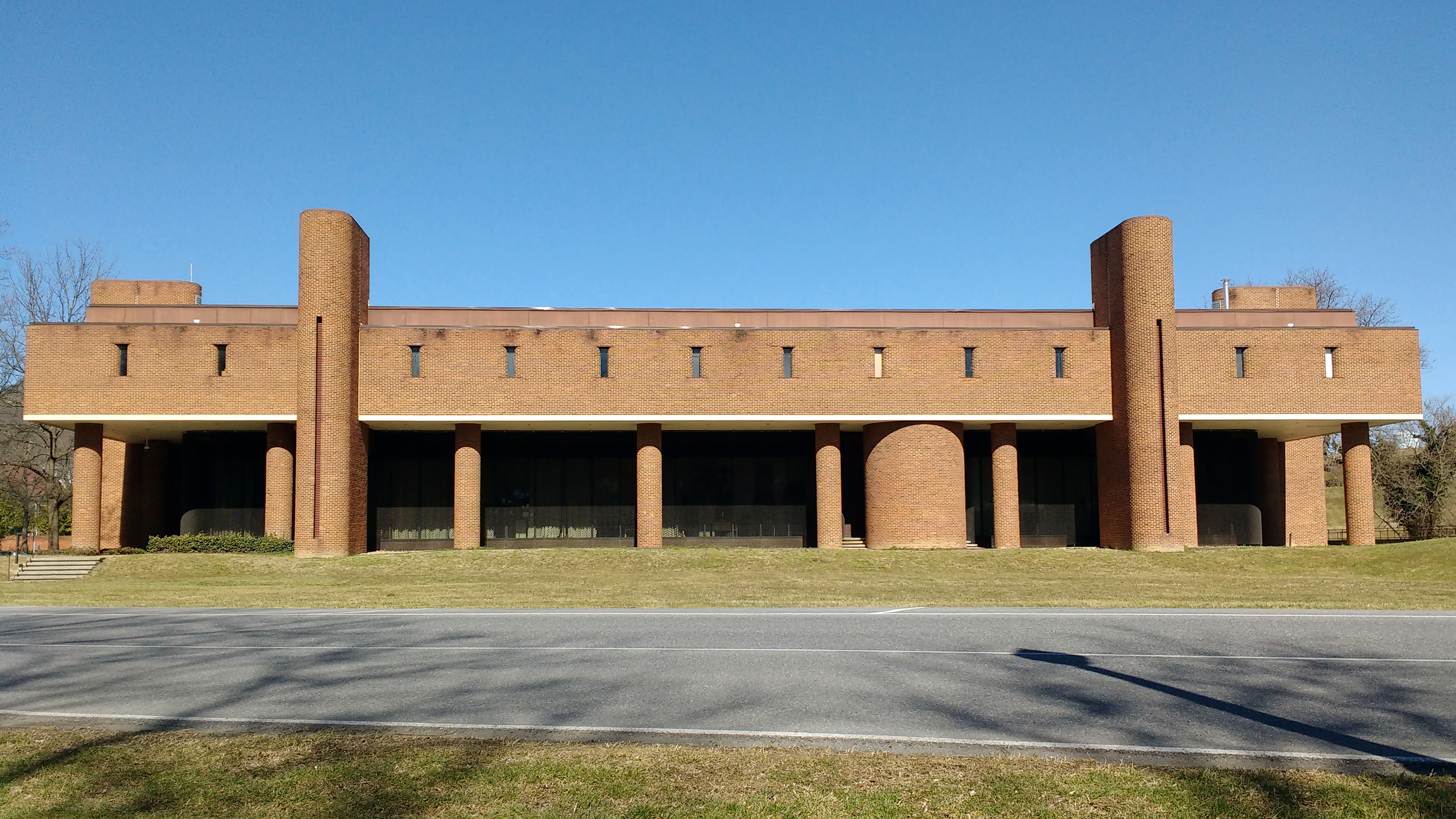
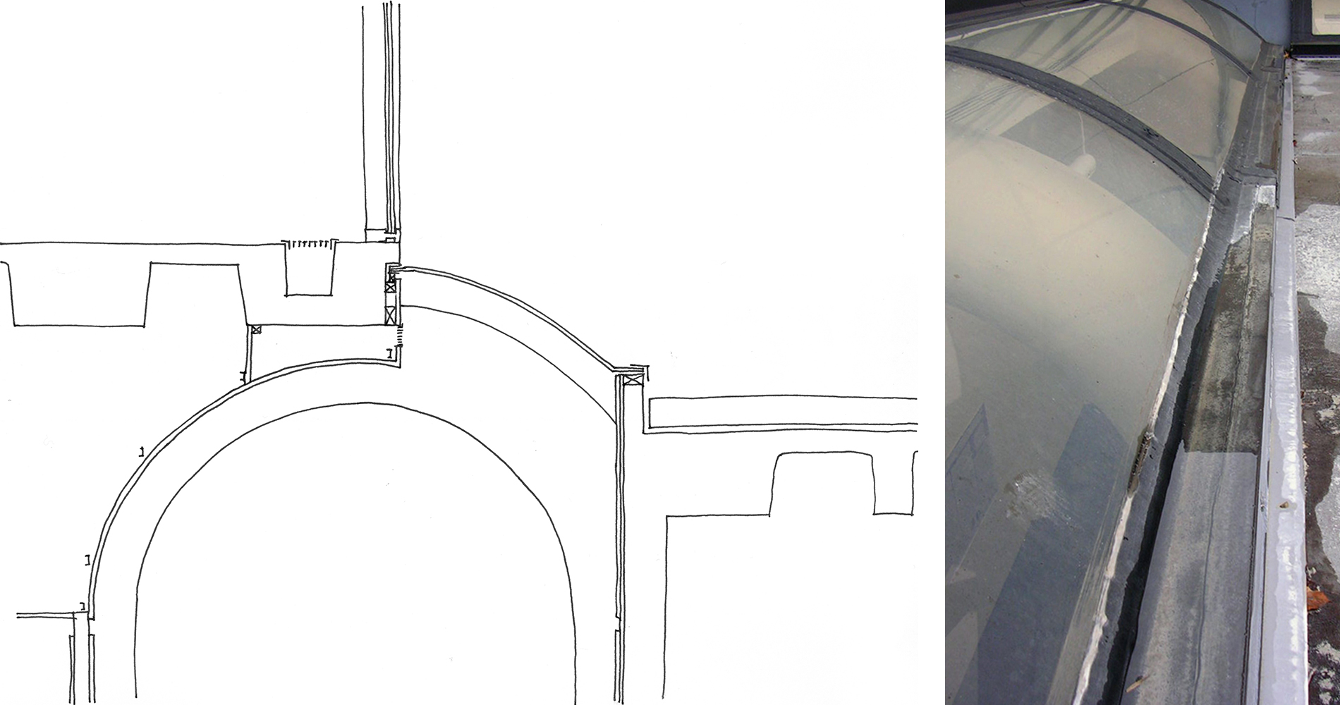
In the scenario shown here, an architect's strict adherence to circular geometry led to significant performance issues. The architect incorporated natural light into a deep educational building's corridor through a series of linear skylights.
Copyright 2018 From Integrating Building Performance with Design by Elizabeth J. Grant. Reproduced by permission of Taylor and Francis Group, LLC, a division of Informa plc.
Adherence to a design goal, without weighing potential pitfalls, led to unexpected consequences in water management within this building.
The quarter-circle skylights, intended to brighten the space, also introduced leaks. Leaks developed at the awkward reglet joint with the slab above, where the quarter-circle becomes dead-level, and at the insufficiently sloped curb below, where the skylight meets an occupiable deck.
Copyright 2018 From Integrating Building Performance with Design by Elizabeth J. Grant. Reproduced by permission of Taylor and Francis Group, LLC, a division of Informa plc.
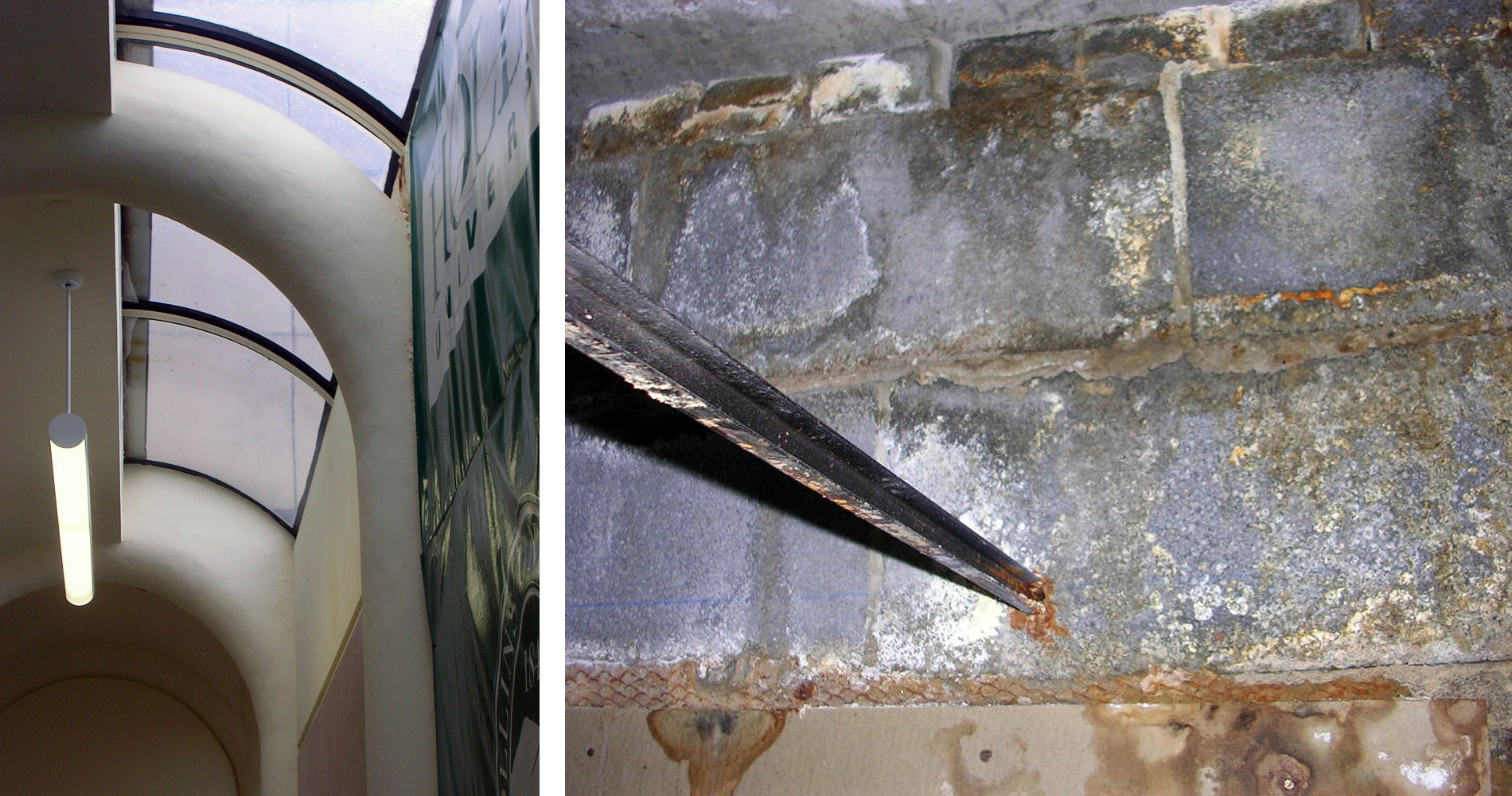
Complex intersections led to water intrusion.
Despite attempts to fix these leaks with tape and caulk, the problems persisted, causing water damage and mold growth below the skylight, concealed by a vinyl banner.
Copyright 2018 From Integrating Building Performance with Design by Elizabeth J. Grant. Reproduced by permission of Taylor and Francis Group, LLC, a division of Informa plc.
Over time, the water facilitated biological growth and deteriorated building materials.
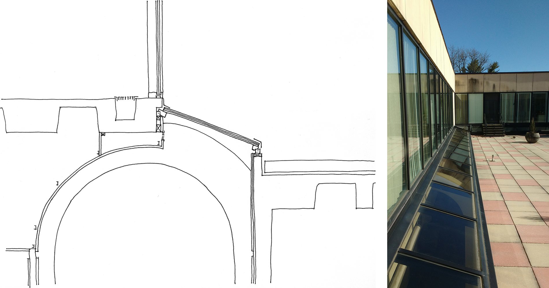
The architects hired to correct these issues violated the original designer’s circular motif with monoslope replacement skylights, removing areas that were insufficiently sloped, a decision made to preserve the building's integrity. This example underscores the importance of considering a building's integrity and future needs over a dedication to aesthetic consistency.
Copyright 2018 From Integrating Building Performance with Design by Elizabeth J. Grant. Reproduced by permission of Taylor and Francis Group, LLC, a division of Informa plc.
Replacement skylights eschewed the original circular design to create better moisture management and preserve the building from further damage.
A Note on Bulk Water Management
Halting liquid water from infiltrating the building enclosure at any point is of first concern when thinking about control layers. Uncontrolled bulk water within a building enclosure is extremely deleterious and renders the other control layers futile. General strategies for bulk water management include sloping to locations where water can be managed and providing capillary breaks between materials where drainage occurs.
On a low-slope roof, for example, the membrane (which can be a single sheet, multiple plies, fluid application or a combination of these approaches) is the first line of defense to prevent the intrusion of bulk water. Water that hits the roof system must then be managed. The phrase “slope to drain and then drip” offers a good first strategy summary. If the roof deck itself does not provide slope, solutions such as tapered insulation should be considered to allow this to happen. [For further information on this topic, please see “Go with the Flow: Tapered Insulation Fundamentals”.] The next step is to ensure continuity at all interfaces, providing properly lapped flashings and membranes such that water cannot get caught on a lip or edge and allowed into the enclosure by way of capillary action or suction at a weakness in the bond between materials.
The roof-to-wall interface is one location where two separate systems must come together to prevent bulk water from entering the building. To do this, a water control membrane (likely a flashing or another accessory product) should be continuous under the coping or edge metal, with the coping sloping inward. This allows water to be directed to internal roof drains. Drip edges on the vertical face of the edge metal are vital to send bulk water out and away from the building, preventing capillary suction from bringing water under the cap.
As is true with all of these barriers, the water control layer’s effectiveness can be greatly reduced by openings and penetrations, even small ones. These discontinuities can be caused by poor design, poor workmanship, damage from other trades, improper sealing and flashing, mechanical forces, aging, and other forms of degradation. Paying attention to the details during the design phase is important as problems are notoriously hard and expensive to fix after the fact, as shown in the skylight detail example.
Planning for Air and Vapor Movement
One of the primary purposes of a building enclosure is to keep moisture out of a building. What makes this difficult is that moisture comes in many forms and can take many paths into a building, not just by way of bulk water. Water vapor can enter a building carried by air and by way of diffusion. The amount of moisture vapor available is dependent on the temperature: warm air is able to hold more moisture than cold air. When warm air cools, it is no longer able to hold as much moisture, so the relative humidity increases, along with the risk of condensation on surfaces. While water vapor itself is not frequently a cause of an issue, it does become an issue when it is allowed to condense at a location where it cannot be managed.
Examining the Visible Impacts of Air
It is important to differentiate between air leakage and vapor diffusion. Air-transported moisture is a bigger issue than vapor diffusion because of the comparative amount of moisture transported during each process. Air-transported water vapor, as the name implies, is carried into or out of a building by air that infiltrates or passes through the building enclosure. Gaps and discontinuities in air barriers within the building enclosure, including at the roof, allow air along with its associated moisture to enter the building (see Figure 8).
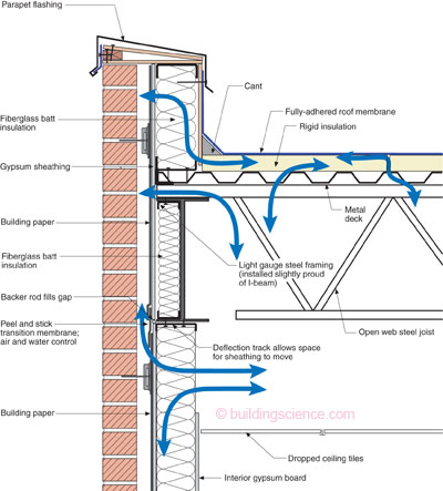
Figure courtesy Building Science Corporation
Not only do gaps allow air transfer, they also expedite uncontrolled migration of moisture.
The National Research Council Canada collected research data that illustrated how even small openings can affect overall air leakage performance. The amount of moisture transported through the building enclosure via an air leakage pathway at normal interior-to-exterior pressure differences is many times greater than the amount of water vapor that can pass through a permeable material due to vapor diffusion alone.4 The importance of a continuous air control layer to manage uncontrolled airflow, and the moisture it carries, cannot be overstated. For example, air leakage can carry about 90 times the amount of moisture through a one-inch square hole in a 4' x 8’ sheet of gypsum board when compared to the transport from vapor diffusion moving through the same 4’ x 8’ sheet (see Figure 9).
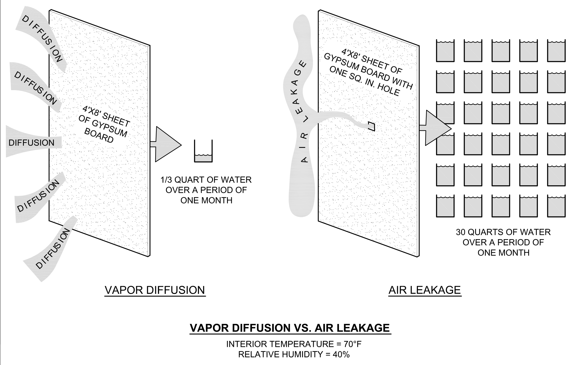
Figure courtesy Building Science Corporation
The impacts of airborne moisture transferred via vapor diffusion and through air leakage in a cold climate.
Most buildings require a continuous air barrier per the model energy code. This means the air barrier must be continuously detailed across the entire building enclosure, including at interfaces, to be effective. To achieve continuity, the air control layer requires much more than selecting a material or specifying a lab-tested assembly. Penetrations, changes in plane, and interfaces such as where the roof meets the wall must be sealed to prevent air leakage that could result in a discontinuity that can lead to condensation problems. This involves potentially multiple trades and manufacturers.
Putting a Halt to Vapor
Water vapor also enters or exits a building by the process of diffusion through building enclosure materials. To understand how this is possible, we return to the second law of thermodynamics mentioned previously:
- Hot moves to cold;
- Moist moves to dry;
- High pressure moves to low pressure;
- Heat, moisture, and pressure always equalize when possible.
Applying the second law of thermodynamics to building science sets forth the following equation: for a conventional building in a northern climate, warm, moist inside air moves outward during the colder winter months. Therefore, the direction of the vapor drive is from the interior to the exterior. This drive notably reverses during the summer, when exterior air is hotter and more humid. In that case, moisture vapor seeks to drive to the interior of a structure, where air is cooler and drier. Buildings in hot and humid climates face vapor drive from the exterior year-round. Regardless of the direction, the moisture vapor is working to get to an equilibrium of both moisture level and vapor pressure by pushing moisture molecules through a material. The amount of moisture that can diffuse through a given material is controlled by the material's water vapor permeance. Regardless of how moisture vapor moves, the water molecules need to reach a surface or location that is at or below the dew point temperature for condensation to occur.
Condensation, which is liquid water, can negatively affect the building in many ways. One example is if condensation accumulates in the insulation layer, it can lead to R-value loss due to water displacing air within the insulation. Additionally, condensation can cause premature degradation of many wall and roof system components, such as rotting wood or rusting metal (including structural components).5 It can also contribute to unwanted biological growth, such as mold. Good news: prevention of these negative effects is possible.
When analyzing the roof, for example, there are three strategies that can help prevent condensation within the assembly:
- Stop the movement of vapor by way of air. The most important way to minimize vapor problems in a roofing assembly is to use and define the air barrier. If air cannot get in, it cannot deposit moisture. This includes detailing at all penetrations and interfaces.
- Stop the movement of vapor by diffusion before it reaches sensitive parts of the assembly. One way to reduce vapor diffusion within a roofing assembly is to use a vapor retarder. Vapor retarders can also act as an air barrier when installed and detailed as such.
- Control the dew point location within the assembly using the thermal control layer. This ensures that any moisture vapor that happens to enter the assembly will not condense in a location where it can cause issues.
Addressing Thermal Control and Continuity
The thermal control layer follows the same principles as the other control layers discussed. The thermal control layer is designed to resist the movement of heat from one side of the building enclosure assembly to the other. Not only is this thermal layer responsible for providing indoor comfort and energy performance, it is also a critical element in preventing moisture damage. Any breaks in the thermal control layer or areas of insufficient insulation will increase the risk of condensation occurring, whether it be from humidity within the conditioned space or uncontrolled water vapor entering the assembly from the exterior.
In recognition of the critical nature of thermal control continuity, the current national model energy code, International Energy Conservation Code (IECC), and ASHRAE 90.1 include basic prescriptive requirements for insulation in both walls and roof systems. Continuous insulation is unambiguous within IECC as well as in the ASHRAE 90.1 standard it references, requiring it on both walls and the roof in all climate zones. IECC 2024 Section C105.2.1 (IECC 2021 C103.2.1) requires the depiction of the thermal enclosure. The amount of insulation required is based on R-value.
Defeating the Thieves of R-value (subhead)
R-value is, in practical terms, the measure of how well insulation resists heat flow across the material in question. Three major thieves that can steal thermal performance, or R-value, from insulation are: air leakage, lack of continuity at interfaces, and thermal bridging such as studs, fasteners or other material attachment methods.
Air leakage carries with it heat in addition to the moisture vapor discussed previously. This is detrimental to the performance of the insulation. Air infiltration and exfiltration makes up 10-40 percent of heat loss through the building enclosure, with the higher numbers found in cold climates.6 This is a key reason why the International Energy Conservation Code (IECC) has required the use of air barriers in building enclosures since 2012.
Thermal control continuity at interfaces is important in order to avoid thermal bridging and risk of condensation at these locations. Thermal continuity is maintained at the roof-to-wall interface by connecting the roof and wall insulation, which can be challenging. Continuity is easiest when the insulation on the outside of the structure versus inside. One example of how to provide continuous insulation at a parapet is shown in Figure 10.
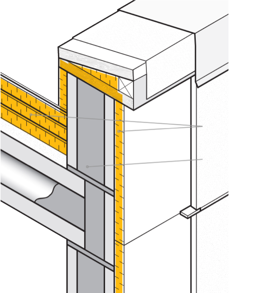
Figure courtesy of GAF/Siplast
Continuous insulation design for a parapet.
Thermal bridging occurs when a more conductive, or poorly insulating, material allows an easy pathway for heat flow across a thermal barrier. ASHRAE 90.1 defines a thermal bridge as an element that has higher thermal conductivity than the surrounding materials, which creates a path of least resistance for heat transfer. IECC 2024 has requirements for mitigating thermal bridging in Section 402.7.
Thermal bridging due to studs is the reason that continuous insulation has a higher effective R-value than insulation that is tucked into the space between framing members. In addition to thermal bridging caused by structural members, thermal bridging also occurs at breaks in the insulation itself. Additionally, the dew point within the building enclosure can be managed more easily with continuous insulation. When building designs split insulation between inside the cavity and outboard of the structure, there are risks for condensation due to the reduced effective R-value of the in-cavity insulation due to thermal bridges of the structure.
As building construction evolves and performance levels of materials increase, it would seem that tiny breaches through the insulating layers of an assembly would matter less and less.7 However, the reverse is actually true: the tighter and better insulated the building, the bigger the difference from all of the weak points in its thermal enclosure. Fasteners and other introduced materials can counteract the ability of insulation to slow and reduce heat flow by acting as a short circuit. Attachment methods used to secure material can create unintended thermal bridges.
Major codes, including the 2024 IECC, address thermal bridging by accounting for framing materials and linear penetrations which act as bridges. Nevertheless, there is a growing body of research pinpointing the impacts of fasteners and attachment methods. Investigators at the National Bureau of Standards, Oak Ridge National Laboratory, the National Research Council Canada, and consulting firms Morrison Hershfield and Simpson Gumpertz & Heger (SGH), have conducted laboratory and computer simulation studies to analyze the effects of point thermal bridges.
A team of researchers at SGH, Virginia Tech, and GAF set out to determine exactly how much of an impact thermal bridges caused by fasteners had on the effective R-value of a roof. They started by simplifying the problem. The team developed computer simulations to accurately anticipate the thermal bridging effects of fasteners based on their characteristics and the characteristics of the roof assemblies in which they are used. The simulation broke the problem of thermal loss down into parts, so that the researchers could know how each part affects the problem as a whole. Researchers also wanted to carefully check the assumptions underlying computer simulations to ensure that results matched up with what the team was finding in the lab. The full paper describing this research work was delivered at the 2023 IIBEC Convention and Trade Show.
The project discovered that one #12 fastener reduced the R-value of a 2' x 2' x 4” thick sample of polyiso board (ISO) alone by 4.2 percent in the physical sample, and 3.4 percent in the computer simulation. The research team found that fasteners in roofs with a steel deck made a big difference in thermal performance as well. Both physical and computer approaches showed the impact of thermal bridging, wherein the steel deck acts like a radiator, exacerbating the effect of the fastener. In the assembly with just ISO and steel deck, adding a fastener resulted in an R-value drop of 11.0 percent for the physical experiment and 4.6 percent for the computer simulation, when compared to the assembly with no fastener. The research also showed that high-density polyisocyanurate cover boards go a long way toward minimizing the thermal impacts of roof fasteners. When a cover board was added, the physical experiment showed a 6.1 percent drop (down from 11 percent with no cover board) and the computer simulation a 4.2 percent drop (down from 4.6 percent with no cover board) in R-value with the addition of a fastener.
Overall, the team concluded that roof fasteners have a measurable impact on the R-value of roof insulation, steel decks amplify this effect, and insulating cover boards mitigate this effect.
These impacts will continue to have an increasing impact on the effective R-value of roof assemblies. Changes in wind speeds, design wind pressures, and roof zones as dictated by ASCE 7-16 and 7-22 have exacerbated thermal bridging potential due to fasteners. Under these provisions, fastener patterns are becoming denser in many cases. This means that there is the potential for more metal penetrating the roof on average per square foot of roof area than ever before. More metal means that more heat can radiate from the building in winter and into the building in summer.
To avoid miscalculating the thermal penalties of thermal bridges, Phius (Passive House Institute US) provides a Fastener Correction Calculator8 along with a way to calculate the effect of linear thermal bridges. A range of codes and voluntary standards are beginning to address this problem, though it is important to note that there is a time lag between development of codes and their widespread adoption.
As more materials and additional requirements are added to enclosures, the design professional needs to recognize when materials and assemblies need to change to achieve higher energy performance and avoid performance failures. “In a broad sense, as energy efficiency is improved in building enclosures, moisture risks can increase from decreased heat flow across the assemblies. As we improve energy efficiency, we may also be increasing moisture risks in building enclosures. And the increased risk may be more complex than the historical designs and more tightly coupled to the building’s HVAC operations, structural elements, and occupant-use conditions.”9
Maintaining a Quality Design
After careful research and selection of materials and design, it is imperative to plan an approach to construction and detailing that prevents changes to the construction documents. A change forced in the field can result in lower realized building performance than originally intended. There are some considerations that should be taken into account to prevent such late changes.
The what?
There are four critical components to a robust detail: the materials selected, the installation methods, a simplification of the detail itself where possible, and thorough communication among design and installation professionals on the previous three components.
Four quick checks can help design professionals ensure that these requirements are met. They are:
- Materials: are the selected materials compatible? Will they adhere to each other where needed?
- Installation Methods: how are the control layers installed and interfaced? What is the order of installation of the different materials? Can the installation be easily completed on the timeline needed?
- Simplify: can fewer materials be used? Can the installation be done in fewer steps or by fewer trades to avoid confusion in the field?
- Communication: is the whole team engaged in conversation to create a multidisciplinary approach? Are details drawn and specifications written clearly to communicate both the materials and the intent of the design professional?
The Why?
The relative importance of each control layer is based upon the magnitude of impact it has on the performance of the building enclosure. As discussed above, the liquid water control layer must be addressed first. Uncontrolled liquid water in a building is extremely deleterious and failures render other control layers less consequential. Second in importance is the air control layer. This is due to its interrelationship with heat and moisture. The thermal control layer is next, as it manages where condensation of moisture vapor could potentially occur. Finally, the water vapor control layer should be considered, taking into account that materials used for the other layers may already be serving this function.
Identifying and maintaining continuity of the four key control layers is important in the design phase. Detailing and identification of the control layers in the drawings is critical to ensuring that the design intent is implemented in the field. This can require the design and specification callouts to be very specific. If the sequencing of components or trades in the field impacts the intended continuity or performance of the control layer in the design, it needs to be addressed before construction starts to prevent rework.
Any of these barriers’ effectiveness can be greatly reduced by discontinuities, even small ones. These openings or flaws can be caused by poor design, damage during construction, improper installation including sealing and flashing, mechanical forces, aging, and other forms of degradation. Thankfully, there are ways to avoid these discontinuities and set up a project for success.
The How!
A specification requiring continuity of control layers, communication amongst trades, verification of material compatibility, and quality control provides the critical key to success.
Designers can include a few fundamental items in their specifications to help ensure the control layers will be installed properly and that the interface details are not missed. First, the specification should set up communication amongst all parties throughout a project to put potential problems under a continual, multidisciplinary spotlight that helps a team to catch them as early as possible, even during the design stage. Items such as defining the complete scope of work for the contractors installing the different control layer assemblies and specifying the party responsible for installing flashing and transitions between systems assigns responsibility and allows for easier scheduling and quality assurance in the field. Clarification on any questions amongst parties should be addressed during a pre-construction meeting at which all parties involved are required to be in attendance.
Second, it is good practice to require shop drawing submittals that include details at the many interfaces around the building enclosure. This will confirm that all participants understand how the materials are to be installed and who will install them. This will also highlight areas that may have been missed in specifications as to which trade is responsible for which part of a specific detail. Critical detail locations are often difficult to illustrate on two-dimensional drawings. They can require exploded diagrams, isometric drawings, and sequenced information to better communicate the design intent. On this note, designers need to define any items labeled “by others” on shop drawings during the review phase. All “others” should be changed to the specific contractor’s name and/or trade.
Next, the materials selected for each part of the system need to be vetted. Questions such as whether the materials will adhere to each other, if they are chemically compatible, and if they can be installed in the order required, should be answered before construction starts. This information, along with support to assist in any detailing questions, should be sought from the manufacturer’s representatives of the chosen products. If substitutions are made, compatibility and adhesion of the components need to be reconfirmed. Additionally, architects can specify mockups in the project documents and even require performance testing of the mock-up to confirm interfaces are functioning as intended. This helps to test and validate the constructability of the design and anticipate issues that may arise during construction prior to the start of work. Mock-ups can also help installation crews by being a reference to the agreed-upon methods and providing orientation for any new crew members on the project. Having a physical example allows for confidence that, when the roof and other assemblies are installed, the team can feel assured that it will perform according to the design intent.
Finally, quality control and operational maintenance are best practices to ensure long-term performance of the building enclosure. It is important to have quality assurance and quality control occur throughout the project and not be confined to a final walk-through in the field. Fixing issues or missed details at the “almost done” stage is very hard when faced with sequencing realities. Operational inspection and maintenance plans can also be required to be submitted for all major systems in the building enclosure.
In Summary
Here is a starting checklist for what is needed in construction documents:
- Show a continuous air barrier.
- Provide details.
- Specify the attachment method of the roof assembly to minimize thermal bridges, such as fasteners.
- What else do you include on your list?
Designers aim to realize a building that is able to satisfy both aesthetics and building science performance criteria. From the designer’s perspective, one of the biggest challenges is meeting this design vision in a way that embraces all relevant performance mandates. While it may be tempting to release responsibility for the way buildings function to contractors, manufacturers, or “others,” building designers are ultimately responsible for satisfying building science performance mandates that result in durable, functional, and beautiful buildings.”10
END NOTES
1 Kesik, Ted J., Ph.D., P.Eng., MASHRAE. “Building Science Concepts.” Whole Building Design Guide. December 4, 2019. https://www.wbdg.org/resources/building-science-concepts. Accessed August 6, 2024.
2Richard D. Rush, ed. The Building Systems Integration Handbook (New York: Wiley, 1986).
3Lstiburek, Joseph. “BSI-001: The Perfect Wall.” July 15, 2010. https://buildingscience.com/documents/insights/bsi-001-the-perfect-wall. Accessed August 6, 2024.
4National Roofing Contractors Association. The NRCA Roofing Manual: Architectural Metal Flashing and Condensation and Air Leakage Control. Page 259. National Roofing Contractors Association. Rosemont, IL. 2022.
5Kirby, James R., Thomas J. Taylor, Ph.D., James Willits. “Condensation, Dew Point, and Roofing.” GAF Roof Views Blog. March 22, 2018. https://www.gaf.com/en-us/blog/building-science/condensation-dew-point-and-roofing-281474980065075. Accessed August 9, 2024.
6“The Hidden Science of High Performing Building Assemblies,” Environmental Building News November 2012.
7Grant, Elizabeth. “Thermal Bridging Through Roof Fasteners: Why the Industry Should Take Note.” GAF Roof Views Blog. November 17, 2023. https://www.gaf.com/en-us/blog/building-science/thermal-bridging-through-roof-fasteners-why-the-industry-should-take-note-281474980286177. Accessed August 9, 2024.
8Fastener Correction Thermal Bridge Calculator. https://www.phius.org/fastener-correction-thermal-bridge-calculator. Accessed August 12, 2024.
9Meyer, Benjamin. “Designing for Moisture Durability & Energy Efficiency.” GAF Roof Views Blog. May 6, 2020.” https://www.gaf.com/en-us/blog/building-science/designing-for-moisture-durability--energy-efficiency-281474980028035. Accessed August 9, 2024.
10Grant, Elizabeth J. Integrating Building Performance with Design: An Architecture Student’s Guidebook. Page 30. Routledge Taylor & Francis Group. New York. 2017.
Andrea Wagner Watts is the Building Science Education Manager for GAF, engaging with industry professionals to provide guidance, technical support and education for roof and wall assemblies. With more than 15 years of experience in the industry, Andrea strives to improve the overall performance of the building enclosures through application innovation, product development and building science research. Andrea has published on building science, assembly interfaces, durability and resilience and holds multiple patents. She serves as an executive board member of ABAA, is the co-chair of their Technical Committee and chairs the ASTM E06 Task Group on air barriers.
Elizabeth Grant, PhD, AIA, is Building & Roofing Science Research Lead at GAF. In this role, she supports architects and specifiers through technical advice in the design process. Before joining GAF, she was an associate professor at Virginia Tech’s School of Architecture + Design, publishing papers, conducting studies, and offering courses. Her architectural experience includes designing healthcare, civic, and educational buildings. Her work focuses on building enclosures and finding sustainable solutions to pressing architectural and environmental problems.
The Building and Roofing Science team offers regional expert building enclosure collaboration through design, specification, and educational support for customers of GAF and Siplast, both Standard Industries companies. GAF is North America’s largest roofing manufacturer with more homes and businesses in the U.S. protected by a GAF roof than any other product. Siplast, a leader in building enclosure systems, offers a portfolio of advanced, high-performance SBS-modified bitumen, PMMA liquid-applied, PVC KEE, lightweight insulating concrete, wall air & water barrier systems, and amenity/vegetated systems.
Originally published in Building Enclosure
Originally published in November 2024
LEARNING OBJECTIVES
- Identify the key aspects of building science and building enclosure design necessary for resilient assemblies.
- Analyze a design’s risk of condensation, based on vapor movement in a building enclosure assembly.
- Define thermal bridging and, using recent research, develop roof system design strategies that minimize the impact of thermal bridging.
- Plan approaches that prevent changes to the specifications, which can result in lower realized building performance.