All Images Courtesy of GAF I Siplast
Sustainability at the Top: The Cool Roof and Energy Implications
When considering a single-ply roof system, building codes can offer an excellent starting point. However, code provides the minimum requirements for construction. Code represent a baseline for design and have few regulatory provisions that focus on resilience. Adding practices targeting energy efficiency and resilience can substantially reduce environmental impacts and improve existing unsustainable design, construction, and operational practices.
Designers can, and often should, design beyond the minimum code requirements to improve the durability and longevity of their roofs. Standard code requirements come from the locally adopted versions of the International Building Code® (IBC) and the International Energy Conservation Code® (IECC) and provide either performance or prescriptive requirements. The code also references specific key standards from documents issued by organizations including ASTM International (ASTM), ASHRAE (The American Society of Heating, Refrigerating and Air-Conditioning Engineers), and The American Society of Civil Engineers (ASCE).
Updated codes have increased the amount of insulation as well as air tightness, and more recently address cool roofing, all of which affects the energy efficiency of a building. Single-ply roofing systems offer many opportunities to contribute to the energy efficiency and resiliency goals of a building when the design includes careful consideration of reflectivity, insulation and airtightness. Understanding the role that each of the assembly components plays in the overall roof design and installation is key to ensuring that the roof assembly will be both durable and sustainable.
Building Code Prescriptive Requirements
Chapter 15 of the IBC provides minimum requirements for the design and construction of roof assemblies and rooftop structures. The chapter addresses Roof Drainage (1502), Weather Protection (1503); Requirements for Roof Coverings (1507); Flashing (1503.2); Coping (1503.3); Wind Resistance of Roofs (1504.1, ASCE 7); and Edge Securement, Low-slope Roofs (1504.5). These include requirements for emergency overflow drainage, gutter securement, and the ability of roofs to withstand wind events, foot traffic, and fires. Roof coverings must be designed and installed in accordance with this code and the manufacturer’s approved instructions. Code considerations must be taken into account during roofing materials selection and installation.
Energy Code – Commercial Requirements
The IECC recognizes the roof’s role in energy performance. Energy codes apply to roofs because the R-value established in the roof assembly and air barrier requirements enable containment of conditioned air inside the building. The roof's contribution towards maintaining the enclosure and keeping the interior environment separate from the exterior means that heating, ventilation, and air conditioning (HVAC) systems do not have to work as hard, resulting in reduced energy consumption.
Under IBC Chapter 13, Energy Efficiency, “Buildings shall be designed and constructed in accordance with the International Energy Conservation Code - 1301.1.1.” Designs can comply with either the requirements of ANSI/ASHRAE/IESNA 90.1 or the requirements of the IECC Commercial Provisions, which apply to all buildings except for residential buildings 3 stories or less in height.
The version of the Code is adopted at the state level; the most recent version is dated 2021, where significant updates were made in regards to the air barrier requirements. Since 2010, the IECC states that a continuous air barrier must be provided throughout the building thermal envelope (2021 IECC §C402.5.1. Air Barriers). The air barrier is permitted to be located on the inside or outside of the building envelope, located within the assemblies composing the envelope, or any combination thereof. The air barrier selected needs to comply with Sections C402.5.1.1 for materials and C402.5.1.2 for assemblies. This section is important as the roof air barrier, whether a dedicated air barrier or the roofing membrane as the air barrier, is required to be continuous across the roof as well as continuously transitioned to the exterior wall air barrier. This requirement is critical to understand when detailing the roof at both roof penetrations (discontinuities) and at the roof to exterior wall interface.
The energy code additionally sets requirements for thermal performance, including a minimum R-value for the roof. This R-value is based on climate zone and geographic location (IECC C301.1 and 90.1 Annex 1). It should be noted that the R-values in the code are denoted as minimum R-values. Owners selecting to achieve higher energy savings, or specialty buildings such as cold storage, frequently need more insulation than required by the code.
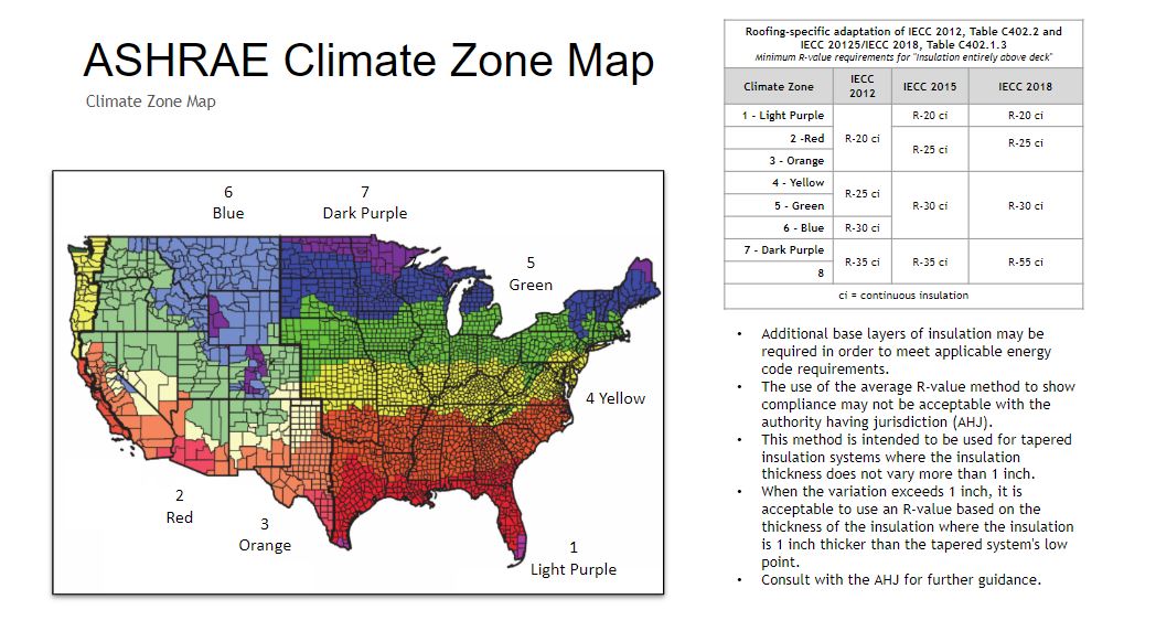
IECC Map with minimum R-value requirements.
Guidelines for installation, as provided by the codes, are also critical to achieving predicted energy efficiency. Starting in 2018, the IECC Section C402.2.1 requires two layers of insulation at the roof and provides that this installation should be staggered and offset during installation, to prevent airflow between the joints.
Cool Roofs 101
Reflective roof membranes, otherwise known as cool roofs, account for greater than 50 percent of roof surfaces installed on low-slope commercial buildings each year, and an even greater percentage are installed in the southern half of the United States. Such reflective roofs have the potential for decreasing cooling energy consumption by lowering roof temperatures (Freund et al. 2006; Ennis and Desjarlais 2009; Gaffin et al. 2010; Graveline 2013).
As defined by the Cool Roof Rating Council®, a cool roof is one “that strongly reflects sunlight (solar energy) and also cools itself by efficiently emitting any heat that was absorbed.” A cool roof does not need to be white. There are many "cool color" products which use darker-colored pigments that are highly reflective in the near infrared (non-visible) portion of the solar spectrum.
The two basic characteristics that determine the "coolness" of a roof are solar reflectance and thermal emittance. Both properties are measured on a scale from 0 to 1, where 1 is 100 percent reflective or emissive.
There is a definitive terminology associated with cool roofing. These terms include emissivity, albedo, reflectivity, and SRI.
Emissivity: Emissivity is defined as the ratio of the energy radiated from a material's surface to that radiated from a perfect emitter, known as a blackbody, at the same temperature and wavelength and under the same viewing conditions. It is a dimensionless number between 0 (for a perfect reflector) and 1 (for a perfect emitter). Simply put, the emissivity of the surface of a material is its effectiveness in emitting energy as thermal radiation or heat. Most roof membranes have an emissivity in the range of 0.85-0.95 and this is not dependent on the color.
Albedo: Albedo is defined as the ratio of the diffuse reflection of solar radiation out of the total solar radiation. It is measured on a scale from 0, corresponding to a black body that absorbs all incident radiation, to 1, corresponding to a body that reflects all incident radiation. It is commonly used in climate science as a measure of the reflectance of solar energy from the earth’s surface. Albedo is the potential for a surface to reflect sunlight. Albedo is different from emissivity in that albedo involves the radiation reflected from a surface, whereas emissivity involves the radiation emitted from a surface.
Reflectivity: Reflectivity is defined as the property of a material to reflect the light or radiation. It is a measurement of reflectance irrespective of the thickness of a material. For most reasonably thick opaque materials, reflection occurs within the first few nanometers of the surface and any light transmitted more than about 100nm into the material is quickly absorbed. Darker membranes like black EPDM have a reflectivity around 0.05, while white TPO and PVC have a reflectivity of 0.8 or higher.
SRI: The Solar Reflectance Index (SRI) is a calculated value using reflectivity and emissivity values. It is an indicator of the ability of a roof surface to return solar energy to the atmosphere. Roofing material surfaces with a higher SRI will be cooler than surfaces with a lower SRI under the same solar energy exposure, especially on a sunny day. SRI values for most materials fall between 0 and 100, although values above that range are possible. Absorptive membranes like black EPDM typically have an SRI less than 10, while White TPO and PVC membranes typically have an SRI above 80. Gray colored roofs are typically lower reflectance with an SRI around 50 and Tan is often mid-reflective with an SRI around 70. There are also specially formulated “energy” colors that are highly reflective without being white.
Many building codes reference SRI or 3-year aged SRI requirements when defining a “cool” roof. The most common of these are the California Energy Commission Title 24, the U.S. Green Building Council’s Leadership in Energy and Environmental Design® (LEED), and ASHRAE 90.1 and 189.1. The Cool Roof Rating Council® (CRRC) offers an online database to look up information on products and set desired inputs. This tool is available at https://coolroofs.org/directory/roof.
Best Practices: Building Science Principles and their Contribution to Roof Performance
How does a roof enhance the performance and efficiency of a building? It can bolster the performance by tackling three tasks: controlling for bulk water concerns, mitigating air and vapor movement, and improving thermal efficiency.
Proper design and installation of a low slope roof is important to meet both performance and building code requirements. As more materials and additional code requirements are added to enclosures, including air tightness, it is important to recognize when materials and assemblies need to adapt in order to accommodate these changes. Most single-ply membranes are Class I vapor retarders, which mitigate moisture migration when they are detailed properly, however, they can also trap moisture within the roof system.
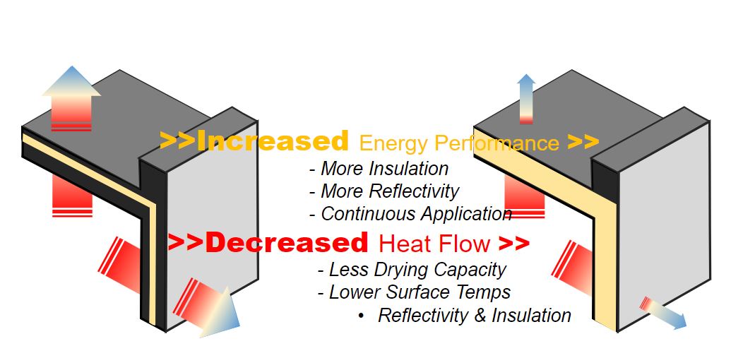
As energy performance is improved in building enclosures, moisture risks can increase from decreased heat flow across the assemblies. Historical roof systems consisted of dark surfaces with little or no insulation. While this did not promote energy efficiency, it allowed for condensation that may have occurred within the assembly to dry into the interior of a building. Today’s roofs often consist of reflective surfaces that reflect heat away from the surface, which do not equally provide the heat that allows for roofs to ‘dry down’ if condensation occurs. Unintended and uncontrolled air movement, vapor movement, and discontinuous control layers can inadvertently bring and trap moisture into the roofing system. Modern day roof materials and their interactions across the roofing assembly, as well as at the roof to wall interfaces, are important to understand so that moisture is adequately controlled.
Mitigating Moisture Concerns - Bulk Water
The first reason for installing roofs is to keep water out of buildings. While there are many types of roof assemblies available, there are three main considerations for managing water intrusion when designing or selecting a roof. Controlling bulk water, such as water from rain or snow, can be accomplished by considering roof slope, membrane seams, and durability such as mitigating damage from storms.
The impacts from moisture intrusion are many, including roof leaks causing headaches to occupants below. Leaks from the roof cause costly repairs, but they also can deteriorate the roof assembly and roof structure, and lessen its performance, including reducing R-values in the insulation. Wet insulation can have a reduced R-value to almost zero when saturated. Water, once it enters into the building, can not only damage interior finishes, but prolonged water infiltration can facilitate mold growth. Mold growth will ultimately affect indoor air quality as it may enter the airspace of the building.
Slope
Positive drainage is key to the durability of a membrane; while some membranes can tolerate standing water better than others, it is a best practice to drain water from the roof and not promote ponding. Standing water can collect organic material, which over time can degrade the roofing membrane. Vegetation is also likely to grow in moist areas on the roof, and the roots of the plants can puncture the roof membrane.
The taper design of the insulation becomes incredibly important, particularly if there is no slope present in the deck. A proper taper design that considers Code requirements, including slope minimums, and drainage around rooftop units will minimize the risk of ponding or standing water accumulating on the top of the roof. Incorporation of slopes that may exceed code minimums may be necessary to adequately drain water as well as crickets to assist in diverting water to drains are critical to ensure that water will drain from the roof.
A proper taper design that considers Code requirements, including slope minimums, and drainage around rooftop units will minimize the risk of ponding or standing water accumulating on the top of the roof.
Membrane Seams
Discontinuities in the membrane, such as at seams and penetrations, represent a potential location for water infiltration into the building below.
As part of membrane selection, consideration of the type of seam between the sheets of membrane can be as important as the membrane selection itself. Different membrane types have variations in seam attachment and strength; these seam attachments also vary by ease of construction in the field. TPO and PVC thermoplastic membranes are installed with seams that are hot-air welded that fuse together to create a monolithic membrane. In thermoplastic membranes, the seam becomes the strongest part of the membrane. Thermoset membranes, such as EPDM seams, are attached with adhesives or tape.
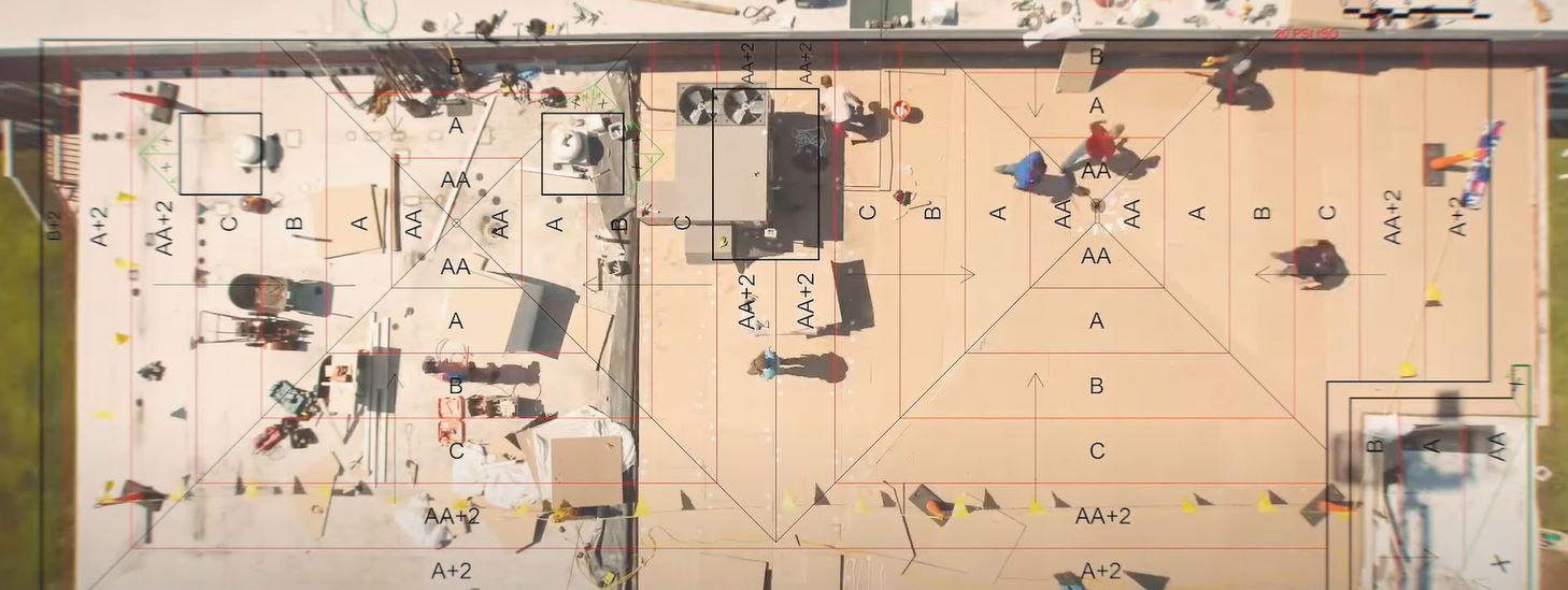
Since membrane seams are common failure points, it is critical to specify adequate field quality control testing during installation. While thermoplastic seams are typically welded with a robotic heat welder, the seam integrity is sensitive to surface temperature and air temperature changes as the sun, clouds, and air influence the temperature and speed requirements on the robotic welder. Seam integrity should be tested throughout the day, particularly in the morning and in the afternoon when there are air temperature changes, as well as after lunch when there are breaks from the installation. For thermoset seams, the seams require cleaning prior to gluing or taping, and it is also important to continually test adhesion since inadequate seam preparation can prematurely fail seam connections.
Performance Durability
Durability over the life of the roof presents a final challenge to roofs, not only from accumulating moisture but from storm damage. The key to preserving a roof’s resistance to water during storms is designing the roof system for resilience. Damage prevention and impact resistance is a system discussion, covering not only the single-ply membrane but also the overall roof attachment method, coverboard use, and insulation selection. Depending on the building location, designing for the impacts of hail can arguably be one of the most important factors to implement durability into roof design. Thicker membranes, including fleece- back membranes offer increased impact resistance for both hail and traffic on the roof. Attachment method becomes crucial, as impact over a fastener can result in a laceration of the membrane. Adhered systems where fasteners are buried in the assembly offer better impact resistance, as well as reduction of the thermal bridging impact. Finally, coverboards can bolster the roof system’s performance as they provide a rigid substrate beneath the membrane. Higher density coverboards should be installed where there is greater risk of hail and increased frequency of foot traffic.
Redundancy becomes key for roofs in areas facing high storm damage risk. A hybrid roof approach blends the best attributes of an asphaltic roof and single-ply membrane together. The redundancy and toughness of an asphaltic membrane overlaid with the lighter colored and ponding water resistance of a single-ply membrane utilizes the strengths of each roof technology. Asphaltic membranes, used as the first layer, provide redundancy and protection against punctures as it adds overall thickness to the system. However, asphaltic systems, such as modified bitumen and built-up roofs, require some type of surfacing to protect them from UV degradation, such as granules, coatings, or ballast. For a hybrid roof, the addition of a single-ply white reflective membrane provides that protection. The single-ply membrane can also be reflective, which decreases the roof surface temperatures and potentially reduces the building's heat island effect as they are commonly white or light in color.
Water damage from slope, seams, and storms can be prevented with proper design and planning. However, the roof also faces challenges from air leakage and vapor diffusion.
Continuous Control Layers
While the concept of continuous control layers is not new, the addition of materials added into the building envelope to increase energy efficiency may inadvertently decrease the drying potential of roof assemblies. In other words, older assemblies utilized less insulation to control interior temperatures, and may have included discontinuous control layers that allowed for uncontrolled air flow that allowed moisture to make its way into roof assemblies. These designs relied on darker membrane colors that allowed for heat gain to dry out the assembly so as not to accumulate moisture which can lead to premature failure of structural elements. As assemblies have increased in efficiency higher R-values and reflectivity, and ultimately air tightness, moisture laden air that does make it into the assembly no longer has the ability to dry out. When not properly detailed, this moisture can accumulate within the assembly causing degradation of materials. Proper design, which includes appropriate insulation, consideration of an air or vapor retarder, and continuity of all of the control layer materials, is the foundation of a high-performing roof.
Water, air, vapor, and thermal control layers, while they may not be separate individual layers, all play an important role in the performance of a roof. Ensuring that the water control layer prevents water from entering into a building is the fundamental reason for a roof. Controlling air and vapor becomes more important as the ability for the roof assembly to dry decreases. The thermal control layer, which is influenced both by codes and energy efficiency, is crucial to maintain interior temperatures. Identifying each of these control layers is the first part of the design process; detailing them to ensure that they are continuous across the field of the roof and properly tied into the exterior walls is what establishes a high performing roof.
Air and Vapor Concerns
Costs due to heating and cooling are often the largest utility bill for building owners, so mitigating loss of conditioned air can be top of mind. According to Environmental Building News, air infiltration and exfiltration make up 25 percent to 40 percent of total heat loss in a cold climate and 10 percent to 15 percent of total heat gain in a hot climate. Losing one-third or more of conditioned air has a significant impact on the operational costs of a building.
However, uncontrolled air movement presents additional hazards to a building besides just increased utility bills. Uncontrolled air is a cause for concern because of the moisture that air carries. Moisture in buildings can be damaging; moisture accumulation can lead to degradation of building materials including mold growth which ultimately impacts indoor air quality. Designing to minimize air flow not only allows a building to save energy but also to mitigate moisture accumulation. Consideration to air barriers and vapor retarders during design are important to mitigate both conditioned air loss and moisture accumulation.
Air Barriers and Vapor Retarders
In 2012, the International Energy Conservation Code (IECC) published air barrier requirements, stating that a “Continuous air barrier shall be provided throughout the building envelope…” The purpose of an air barrier is straightforward: first, to minimize the loss of conditioned air from within a building, and second, to reduce energy loss and increase building energy efficiency.
Uncontrolled air movement in and out of a building is a key contributor to heat loss and gain. It is important to distinguish that the air barrier is often a system of materials that controls air leakage and convective heat flow through the building enclosure from the interior to the exterior. The air barrier is, critically, not one material, but instead is an integrated system of many different materials and components. As such, the connection of air barriers at interfaces, such as the roof to exterior wall interface, is critical.
Detailing to ensure continuity of the air barrier helps guard the building’s energy efficiency. It is the responsibility of the registered design professional to determine the need for an air barrier, verify an air barrier’s compatibility with other materials, clearly identify all air barrier components within the envelope, and provide details on joints, penetrations, and transition areas. While most often the roof membrane is considered the air barrier, other times, a dedicated vapor retarder at the deck level serves as both the vapor retarder and the air barrier. The building designer should specify that the roof air barrier not just overlap the wall air barrier, but also be flashed or sealed to it so that air cannot move through the interface.
It is important to distinguish that a vapor retarder is always an air barrier if detailed as such, but an air barrier may not control vapor movement. Additionally, while air barriers are a code requirement, vapor retarders are currently not. Vapor retarders are typically used in roofing assemblies when there is increased moisture content in interior air, such as over an indoor natatorium. Similar to air barriers, vapor retarders should be continuous at any penetrations and roof to wall interfaces in order to adequately prevent moisture vapor from entering into the roof system. It is important to remember that air leakage can cause more moisture-related problems than vapor diffusion.
Condensation
Contrary to popular belief, air-transported moisture is much more critical to control than water vapor that enters a building by diffusion; condensation is likely to occur when moisture vapor in uncontrolled air is allowed to reach dew point. For interiors with high humidity, such as natatoriums, it is often more obvious to consider the inclusion of a vapor retarder at the deck level to limit condensation potential, but controlling air leakage, and the associated moisture that air contains, can be of added difficulty when there are sources of moisture from the exterior to the interior of the building.
Control of moisture ingress from air leakage at assembly joints, including those at the roof to wall interface, are where the vapor control layer can have the greatest impact on condensation potential in roof assemblies. Proper design includes ensuring that the transitions and gaps between materials are sealed. Inadequate design, where there are discontinuous control layers, allows for warm, moist air to enter into the roof assembly and mix with cooler air. When the warm, moist air meets a surface below the dewpoint, condensation forms. Often, there is little to no drying potential within roof assemblies, and the moisture is trapped. Trapped moisture can lead to degradation of roofing materials, including decreased R-value of insulation and rotten wood decks.
Traditionally, darker colored roofs with the roof membrane performing as the air control layer have allowed for roof assemblies to ‘dry’ when condensation is introduced into an assembly. The darker membranes allow for the roof to ‘heat up’ and effectively evaporate condensation that may have occurred over the course of the day. While a darker colored roof may allow for the moisture to dry, there is a fundamental flaw with the theory that this is an acceptable way to design for a roof. Introduction of moisture into a roof assembly may degrade roofing materials over time, albeit slower than if the moisture was trapped. There is further misconception that by installing white or reflective roofs, the roofs no longer have the capability to dry. The theory is that since white roofs will reflect the sun’s rays and are not allowing for as much heat gain into the roof assembly, trapped moisture will not dry out. While this may or may not be true for a specific building in a specific location, roofs should be designed to prevent moisture infiltration and reduce condensation potential by including continuous control layers that prevent uncontrolled air and vapor movement.
Thermal Concerns
Managing thermal concerns at the roof centers around appropriate insulation, system attachment, and continuity at details. Attention to detail, including thermal bridges at critical intersections and perimeters, is important for energy efficiency over the life of the roof.
While insulation selection is important, the overall R-value of the system and its installation should meet code requirements and the desired energy efficiency of the roof. As referenced in the IBC, the IECC 2018: C402.2 denotes minimum R-values based on the climate zone where the project is located. The IECC indicates:
- “Continuous insulation … shall be installed in not less than two layers ...”
- “…and the edge joints between each layer of insulation shall be staggered.”
Thermal bridging, which is when heat loss occurs from a discontinuity in R-value between materials, occurs when there are gaps in the insulation such as between board joints. Adding a second layer of insulation and staggering the joints on the boards below mitigates thermal bridging between board joints. Another common place for thermal bridging to occur is at transitions, particularly at the roof to wall interface, and the code requirement for continuous insulation addresses this by requiring the insulation be continuous from the roof to the exterior wall. Another common location for thermal bridging to occur is at fasteners attaching the roof assembly to the structure.
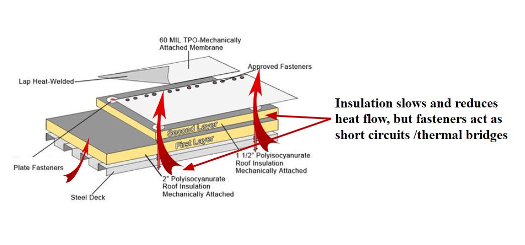
There are numerous methods to attach roof assemblies to the roof deck: the method depends on deck type, wind uplift required, and budget. Deck types vary from wood, to steel, to concrete, where steel decks are the most common. Roof assemblies are typically adhered to concrete decks and even when fasteners are used, they do not penetrate through the entire deck, so thermal bridging is of little concern. In wood and steel decks, however, fasteners are commonly used to attach roof assemblies, and they must penetrate through the deck in order to ensure adequate attachment of the roof system above. The location of the fastener head and plate within the roof assembly has a large impact on the effect of thermal bridging in an assembly. In a typical mechanically attached system, such as in the graphic below, fasteners are installed through all of the layers of insulation and cover board and into the structural deck. This allows for heat transfer from the interior through the fasteners. Fasteners that span from the roof deck through the insulation and cover board can result in a loss of up to 17 percent in R-value. A way to reduce the effect of thermal bridging is to bury the fasteners in the system and install them down as close to the deck as possible, and then adhere subsequent layers of insulation on top. Mechanically attaching the first layer of insulation and adhering the second layer reduces the potential impact to only a 4 percent loss in R-value.
Ultimately, improved energy efficiency at the roof can begin with enhancing solar reflectivity. But if this is not founded on solid specifications that protect the roof against water, air and vapor, and thermal loss, those gains are lost. Cool roof performance needs to be supported by prevention of uncontrolled air movement, proper insulation, and with mitigation of thermal bridging.
Selecting the Best Actor: Contributions of Single-Ply Roofing to Energy Efficiency
Single-ply membrane types include EPDM, TPO, and PVC. The primary differences between the membrane types is their chemical composition, their performance when exposed to chemicals at the roof surface, and treatment of the seams during installation. Since the chemical make-up of each of the membranes is different, certain membrane types are more suitable for different applications.
Single-ply membranes are, as their name implies, a single layer of membrane roof material and are produced in rolls. Single-ply membranes are the most popular roofing membrane today due to their ease of installation and relatively low cost. Due to the nature of a single-ply roof, it can generally be installed more quickly than a multi-layer modified bitumen or built-up asphaltic roof system.
Essential Elements of All Single-Ply Membrane Roofing
Single-ply roofing use in North America traces its origins back to the early 1960s. Since then, single-ply roofing has grown in popularity due to its long service life, dependability, and ease of installation.
Modern single-ply sheets utilize a composite made up comprised of:
- The cap layer, associated with the membrane’s performance relative to the elements,
- The reinforcing scrim in the middle, and
- The core layer that forms the bottom of the sheet.
The cap, or top layer of a single-ply membrane, provides most of the weather protection. It features higher content of both heat and UV stabilizers.
Early thermoplastic single-ply membranes were unreinforced which led to premature failures for certain membranes. In today's single-ply roofing sheets, reinforcement provides dimensional stability, puncture resistance, and limits thermal expansion.
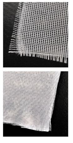
Image shows a low wicking 9 x 9 weft polyester scrim, coated to improve ply adhesion. Windows allow top and bottom layers to fuse together. Bottom reinforcement fabric, must be “primed” before coating during manufacturing.
Reinforcing scrim may be polyester or fiberglass. Polyester scrim is the most common scrim used in the industry and is compatible in mechanically attached, induction welded systems, and adhered methods. Polyester scrim offers a higher point load resistance. Fiberglass reinforcement is not as common and can only be used in adhered systems. However, fiberglass scrim offers more dimensional stability and lower thermal expansion.
The importance of the core, or bottom element of the single-ply membrane, is to facilitate welding to the cap of the adjacent sheet. The core contains an almost identical formula to the cap. The material differs in that it has less heat and UV stabilizers. For cool roof single-ply membranes, no white pigment is needed in the core. Balanced sheets have an equal size cap and core.
Types of Single-Ply Membranes
EPDM (Ethylene Propylene Diene Monomer)
EPDM was first introduced to the automotive industry in the 1960’s and is often referred to as a rubber roof. EPDM quickly gained popularity due to its ease and speed of installation as it is manufactured in rolls that are shipped to the site and installed onto the roof as a single layer. Currently, EPDM roof installations account for approximately 15 percent of the commercial roofing market. EPDM is typically black in color due to its key ingredient of carbon black. However, white EPDM can be manufactured with a different formulation and is available often at an increased price and decreased UV resistance when compared to black EPDM.
EPDM is available in large sheets, which are flexible and bend easily at transitions making it easy to install. Because EPDM is a thermoset material, seams between sheets must be glued or taped, which can lose adhesion over time, especially if not prepared properly during installation. Additionally, EPDM is prone to shrinkage over time, which can put stress on the glued or taped seams if not detailed properly. EPDM has poor resistance to acids, greases, oils, and is incompatible with asphaltic products. Compatibility for any potential chemicals on the roof should always be confirmed with the manufacturer.
EPDM is typically manufactured in thicknesses ranging from 45 to 90 mils and is versatile in its attachment method as it can be mechanically attached, ballasted or adhered, which makes it ideal for a wide range of applications.
Performance highlights:
- Available in very large sheets.
- Very flexible and easy to bend at transitions.
- White EPDM is available but with added cost.
TPO (Thermoplastic Polyolefin)
TPO membranes were first introduced into the roofing market in the early 1980’s and were standardized with the creation of ASTM D6878 in 2003. Currently, TPO has greater than 50 percent of the low slope commercial roofing market share due to its lower material cost and speed of installation.
TPO membranes consist of three main components: a UV resistant cap, a core (reinforcement scrim), and a base. These three components are fused together during the manufacturing process. The cap and the core consist of similar components, but the cap contains UV and heat stabilizers, which provide long-term weathering resistance. TPO is inherently flexible without the use of plasticizers and dimensionally stable over time. Due to its chemical composition, TPO is naturally fungal resistant and has generally good resistance to chemicals. However, acids, greases, and oils should be avoided. Compatibility for any potential chemicals on the roof should always be confirmed.
TPO is manufactured in rolls that are shipped to the site and rolled onto the roof with no additional membrane layers required. After the membrane is rolled out onto the roof, the seams are heat welded together. When welded at the proper speed and temperature, the seam becomes monolithic with the rest of the roof membrane and is the strongest component of the roof. TPO membranes are typically white in color, but can be manufactured in a range of standard and custom colors, including various reflective colors other than just white. It is therefore highly popular for cool roofing applications.
TPO is typically manufactured in thicknesses of 45 mil, 60 mil, and 80 mils, with and without fleece backing, and they can be mechanically attached, adhered, ballasted, and induction welded. The wide range of thicknesses and installation methods make TPO a versatile choice for a wide range of applications.
Performance highlights:
- Strong, heat-welded seams.
- Inherently flexible, contains no plasticizers.
- Will not gray over time and has no fungal growth in warm climates.
PVC (Polyvinyl Chloride)
PVC roofing was created in Switzerland and Germany in the 1960’s and was subsequently introduced to the US in the 1970’s. This single-ply membrane is flexible which allows for easier detailing. PVC also offers increased chemical resistance compared to EPDM and TPO. PVC has a steady market share due to its increased resistance to oil, grease, and chemicals.
PVC is a thermoplastic like TPO and the seams are heat welded together. The seam becomes a monolithic component roof and is the strongest component of the roof. PVC membranes are typically white in color, but can be manufactured in a range of standard and custom colors, including various reflective membranes other than just white. PVC is typically manufactured in thicknesses of 50 mil, 60 mil, and 80 mil, with and without fleece backing, and it can be mechanically attached, adhered, ballasted, and induction welded.
Standard PVC membranes consist of a liquid plasticizer that enables the PVC polymer to become flexible. Over time, the liquid plasticizer can leach out of the membrane and cause the membrane to become more rigid again, which in extreme cases can lead to cracking under stress or movement. While this was a concern with early PVC membranes, in current formulations this is less of a concern unless it is put in contact with asphaltic products which cause the plasticizers to leach out at a faster rate. As with any roofing membrane, compatibility for any potential chemicals on the roof should always be confirmed. Over time algae and mildew may grow on the membrane surface largely due to the migration of the liquid plasticizers, this growth can negatively impact reflectivity.
Performance Highlights:
- Excellent resistance to oil and grease.
- Very flexible during installation, good for detailing.
- Reflective colors available.
PVC KEE is a variation of a PVC membrane that includes a solid plasticizer known as KEE (Ketone Ethylene Ester). This solid plasticizer does not leach from the membrane and provides enhanced weatherability as a result. PVC KEE also has best in class resistance to chemicals including jet fuel, oils, and greases, and is ideal for restaurant or airport roofing applications.
Performance Highlights:
- Better long-term weathering.
- Best in class resistance to oil and grease.
- Remains flexible over lifecycle.
Material Comparison
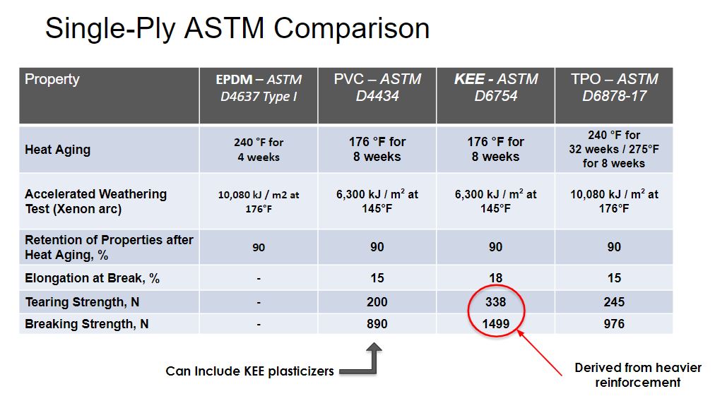
ASTM standards have been developed to provide the minimum quality standards for manufacturers to follow. Viewing them side by side can offer a useful comparison when deciding between single-ply roofing membrane material types for a given project. The table below highlights some of the differences in performance characteristics and accelerated weathering requirements for the different single-ply membranes.
Selecting Your Supporting Cast: Roof Attachments and the Role in Roof Durability
While the single-ply membrane may take the starring role, a roofing "system" is composed of multiple components that must work together to provide the best overall protection.
The basic roof components for a low-slope commercial roof may include:
- Roof deck
- Substrate board/roof board & vapor retarder/air barrier
- Insulation–2 layers minimum
- Cover board
- Roof membrane
- Overburden (elements like vegetation, ballast, or solar installations)
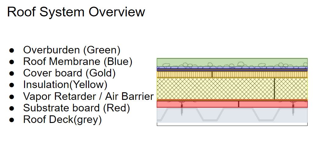
Basic roof components of a low-slope roof.
The Roof Deck
There are three main roof deck types, classified by material: metal, wood, and concrete. Roof deck selection is influenced by the building construction type, building use, and regional construction trends. Each has their own implications to roof system selection including roof attachment methods and reaction to moisture.
Substrate Board/Roof Board and Vapor Retarder/Air Barrier
While not every roof assembly requires a dedicated vapor retarder or air barrier, it is important to know when one should be installed as well as recognize when it should not. Most often the roofing membrane functions as both the air barrier and the vapor retarder, however, controlling moisture is critical in roofing assemblies, and the use of a dedicated air barrier/vapor retarder may assist in doing this. A best practice is to install a vapor retarder on a concrete deck or over a building with high interior humidity, such as a natatorium, where there is a higher potential for moisture vapor to enter into the roof assembly. For buildings with fluted steel decks, a substrate board can provide a solid substrate for the vapor retarder when one is needed.
Incorrect placement of a vapor retarder can inadvertently trap moisture, and therefore, it can be a better design choice to not install a vapor retarder than to install it in the wrong configuration. The location and presence of a vapor retarder should be confirmed by hygrothermal analysis or a qualified design professional. Additionally, detailing for any air or vapor barrier is important as it must be continuous across the roof and tied into the wall air or vapor barrier, without interruptions, in order for it to function as intended.
Insulation
Rigid roof insulation is typically installed above the roof deck in most commercial assemblies. The most common insulation materials for commercial low slope roofs include polyisocyanurate (polyiso), expanded polystyrene (EPS), and extruded polystyrene (XPS). Other types such as mineral wool and vacuum insulated panels (VIP) are also available and installed in various roofing assemblies.
The selection of insulation should consider the various properties of the insulations; each of these types have their place in the market. Providing adequate insulation is critical in roofing assemblies for overall energy efficiency of the building. The higher the R-value, expressed per inch, the better the thermal performance of the insulation and its effectiveness at maintaining interior temperatures. One factor to consider when selecting a material for existing roofs where termination heights are limited, is that a material with a higher R-value per inch can reduce the height of the insulation to help designers meet the height restrictions. Vacuum insulated panels can be well suited for this. Besides thermal resistance and a stable R-value, the insulation’s compatibility with adhesives, its component compatibility, water absorption, and compressive strength all need to be compared prior to selecting a material.
Polyiso has become the dominant insulation for commercial roofing, making up more than 70 percent of the market. Polyiso insulation is manufactured with a facer on each the top and bottom of the board. Two types of facers are available: glass fiber reinforced facers (GRF) and coated glass facers (CGF). GRF are made with organic fibers, and CGF are made with inorganic fibers; CGF provides improved moisture protection and resistance to mold. Due to the facers, adhesives used in many adhered systems do not adversely affect polyiso, allowing it superior solvent compatibility when compared with polystyrene foams.
Improper installation of insulation can impact overall roof performance. Insulation boards are required to be installed so that the joints are staggered and offset, and at least two layers of insulation should be installed rather than just one thick layer. Gaps between boards can decrease insulating ability by allowing thermal loss, as well as an increased condensation potential if air travels into and through the roof assembly. Air flowing between the boards also brings moisture, which if allowed to condense, can saturate the insulation boards.
Coverboards
Coverboards are installed directly below the roof membrane and above the primary insulation layer, to prolong the life of the roof system, as they offer protection against fire, puncture resistance from hail or heavy traffic. High density (HD) polyiso, glass mat, cementitious, and gypsum coverboards are the most common on the market today. Wood fiber and perlite are also available, although installed less frequently. Each has their advantages and considerations, including capability to resist hail and fire, and installation convenience. Coverboard selection also depends on the activities planned on the roof: for example, a higher compressive strength will be needed for solar or overburden installations, areas that experience larger hail, or high foot traffic zones. Coverboards also provide added protection against penetration, including tools dropped by service contractors. Coverboards not only increase the durability and resilience of a roof, but are considered a best practice to protect the entire roof assembly. Incorporating a coverboard into a roof assembly decreases overall lifecycle costs as replacement cycles are lengthened since the addition of the coverboard will mitigate damage from impact or foot traffic.
Coverboard selection may be influenced by ease of installation including weight of materials and ability to easily cut on-site. Wood fiber boards quickly became replaced in the market by newer technologies due to its heavy weight and the need for saws to cut it. Most other technologies only require the use of a utility knife. The weight of the boards also varies by material type. HD polyiso is very light and easy to cut, whereas glass mat gypsum is heavier, but is a good option in areas where there is risk for larger hail stones.
Many insurance companies, including FM Global, may require a coverboard based on building location. FM Global has divided the contiguous US into three hail zones: Moderate Hail Zone, Severe Hail Zone, and Very Severe Hail Zone. The hail zones are divided based on the likelihood that a hail stone of a particular size occurs in that zone. The selection of a coverboard will be determined by its ability to resist damage from hail of a particular size. For example, most coverboards available meet Severe Hail requirements, but only glass mat gypsum coverboards and plywood meet the test requirements of Very Severe Hail.
A word of Caution: Attachment Methods for Single-Ply Membranes and Performance Implications
Single-ply membranes tolerate a wide variety of attachment methods and are able to be mechanically attached, adhered, or ballasted. The types of adhesives can vary depending on membrane type, the ambient temperature during installation, and local VOC regulations. Mechanical attachment and ballast is often more cost effective, but have considerations such as added weight for ballast and membrane flutter.
Mechanically Attached Systems
Mechanically attached systems are often associated with single-ply systems, as these membrane types regularly use fasteners to install both the insulation layers and the membrane. For an appropriate installation, the fasteners are installed at the membrane laps and must penetrate through or engage the proper depth into the structural roof deck for securement. The number of fasteners will depend on project specific requirements, but typically for a mechanically attached system, there is a minimum of six fasteners per 4’x8’ insulation board, and additional fasteners along each membrane seam for membrane attachment. This can lead to a substantial number of fasteners penetrating and creating thermal bridges within the roof assembly, reducing the effective R-value on the roof.
Mechanically attached single-ply systems are also subject to billowing in high wind events. Billowing or fluttering of a membrane is when wind causes a negative pressure by pulling interior air into the roof assembly creating uplift force on the roof assembly. Although this is an acceptable behavior of single-ply membranes, it can cause stress and fatigue on the mechanical attachments and membrane over time. Interior air that is pulled into the roof assembly equates to energy loss since often the temperature controlled air may be warm or cool based on the temperature of the membrane, and may present a condensation risk depending on outside temperatures.
It should be noted that mechanically attached single-ply systems are commonplace in the market and have had many years of successful installations. These systems are also able to achieve high wind uplift ratings due to the direct attachment to the roof deck and have no fumes associated with the installation.
Adhered Systems
Systems that use adhesives to secure the roof assembly and do not use fasteners, greatly reduce thermal bridging by eliminating the heat path from the interior of the roofing assembly to the exterior. Adhering also prevents billowing of the membrane, and mitigates the amount of interior air that can be brought into the roof assembly.
Adhered systems may mean that all layers are adhered or that only the membrane is adhered or it may include a mix of adhered and mechanical attachment of some or all of the layers within the assembly. If thermal bridging of fasteners is a concern, attaching only the substrate board or first layer of insulation and adhering the second layer, cover board, and membrane can significantly reduce interior air loss and thermal bridging.
Induction Welded Attachment
Induction welded fasteners are another type of roof attachment that is installed frequently in the thermoplastic single-ply roofing market. The technique fastens TPO and PVC membranes to the substrate below using a microprocessor-controlled induction welding machine. The thermoplastic roof membrane is welded directly to specially coated fastening plates used to attach the insulation. The combined insulation and membrane fasteners resist wind uplift forces, so that wind loads are more uniformly distributed versus a conventionally attached system. By definition, this is a mechanical attachment method, but the fasteners can be installed in the field of the sheet since they are welded to the underside instead of penetrating the membrane only at the laps. Thermal bridging is also reduced, compared to traditional mechanically attached membrane systems as there are less fasteners required for this installation. There are no application temperature restrictions and there are no fumes or fire hazards associated with the installation.
Single-Ply membranes can be installed in any climate as long as each component is thoughtfully designed.
In Closing
Roofing assembly selection plays an extremely important role in protecting the building from the elements, impacting energy efficiency, and contributing to the resilience goals of a building. Single-ply roof membranes are the largest sector of the low-slope market and can contribute to these building goals. It is important for the designer to consider material selection for each layer in the assembly, including how the entire roof assembly will perform over time.
Selecting a reflective or light colored membrane is a common choice when a building is opting to divert solar heat gain from entering into the building. Reflecting the solar heat gain can be advantageous in warm climates, but also in cold climates since the sun’s energy is often greater in the summer due to longer days and the angle of the sun. Designers must also select the appropriate amount of insulation for thermal efficiency, including the consideration of a coverboard to protect the system from hail and foot traffic over the life of the roof. Additionally the system attachment method will influence the impact of thermal bridging and subsequent building energy loss, since an adhered system will mitigate the effects of thermal bridging from fasteners.
While system selection is important, as energy performance of building enclosures continues to improve, moisture risks can increase from decreased heat flow across the assemblies if uncontrolled air movement, vapor movement, and discontinuous control layers inadvertently trap moisture into the roofing system. Continuous control layers, including water, thermal, air, and vapor control, across the roof and tied-into the exterior walls will limit the condensation potential within a roof assembly. Designers should incorporate continuous control layers into each roof detail including at transitions and penetrations.
After design, the roof system installation, including quality assurance measures to ensure that seams are installed correctly and slope is provided to drain, are critical to limit water intrusion and increase the life of the roof system after installation is complete.
The key elements for improving energy efficiency are:
- Selecting the type of single-ply membrane including consideration to attachment and color
- Selection of the amount of insulation including attachment method
- Adequate detailing including consideration to continuous control layers
- Perform QA/QC during construction to ensure quality installation
Single-ply roofing assemblies offer many opportunities to contribute to the energy efficiency and resiliency goals of a building, and it includes careful consideration of each of the assembly components, the overall roof design, and the installation to ensure the roof assembly meets these goals.
Bozeman Public Safety Center

Bozeman, Montana
Complete September 2022
Roofing materials summary
- TPO 60 mil smooth membrane
- Sprayable, solvent-based adhesive
- High-density polyiso coverboard
- Polyiso Insulation, flat and tapered panels
- Self-adhered vapor-barrier direct to deck
The Bozeman Public Safety Center houses the Bozeman Police Department, a fire station, the Municipal Courts, and Prosecution and Victim Services. The ambitious new construction project encompasses 95,000 square feet. The facility needed a roof system that would withstand the tough Montana winter weather, including hail resistance, for decades to come.
The architect on the project, ThinkOne Architecture, specified a TPO system which was installed by Summit Roofing, a Master Select Commercial Roofing Contractor with offices in Missoula and Helena, Montana.
Roof Installation
The 55,000-square-foot steel roof deck was first covered with a self-adhered vapor retarder, which was directly applied to the deck. The intent of the vapor barrier was to function as the air control layer and to mitigate interior moisture from migrating into the roof assembly. Two 3-inch layers of polyisocyanurate insulation were installed, with the first layer mechanically attached and the second adhered. The system attachment method buried the fasteners by mechanically attaching the first layer and decreasing thermal bridging caused by fasteners penetrating the insulation. Tapered polyiso was adhered to flat roof sections to ensure proper drainage. Due to the risk of hail, a half-inch layer of high density polyiso was adhered to the insulation. The high-density polyiso provides an R-value of 2.5 per half inch, as well as resistance to Severe Hail. A 60-mil TPO membrane was fully adhered using a quick spray adhesive. The adhered roof membrane removed the effects of thermal bridging that would have been caused by a mechanically attached system.
Erin Andes, PE, LEED A.P., is a Building Design Manager for GAF, focusing on the Western U.S. As a member of the GAF Building and Roofing Science Team, she works with designers to review project designs to mitigate risk and achieve affordable, durable, watertight, and energy-efficient roof assemblies. Andes is a Professional Engineer in multiple states and holds a Master's Degree in Civil Engineering from Georgia Institute of Technology.
Kristin Westover, PE, LEED AP O+M, is a Technical Manager of Specialty Installations for low-slope commercial roofing systems at GAF. She specializes in cold storage roofing assemblies where she provides insight, education, and best practices as it relates to cold storage roofing. Kristin is part of the Building and Roofing Science Team where she works with designers on all types of low-slope roofing projects to review project design considerations so designers can make informed roof assembly decisions.