This CE Center article is no longer eligible for receiving credits.
Cover Boards and Insulation
The advantages of greater membrane thickness have been demonstrated. However, roof durability is system dependent so we must look beyond the membrane and consider the entire roof assembly. Rooftops with PV arrays are burdened with more trades and increased foot traffic on the roof, and therefore, are more susceptible to degradation and potential leak sources. A logical starting point is to protect high traffic areas with walkway pads.
The addition of a high-compressive-strength cover board below the single-ply roof membrane will also enhance system protection and extend the life expectancy of the roof. Cover boards provide added protection against penetration by objects, including tools dropped by service contractors, wind-borne debris, and hail. Increasing the thickness of the cover board will increase its penetration resistance. The use of high-density polyiso or gypsum cover boards can significantly increase penetration resistance by nearly 250 percent, as shown in Figure 3.
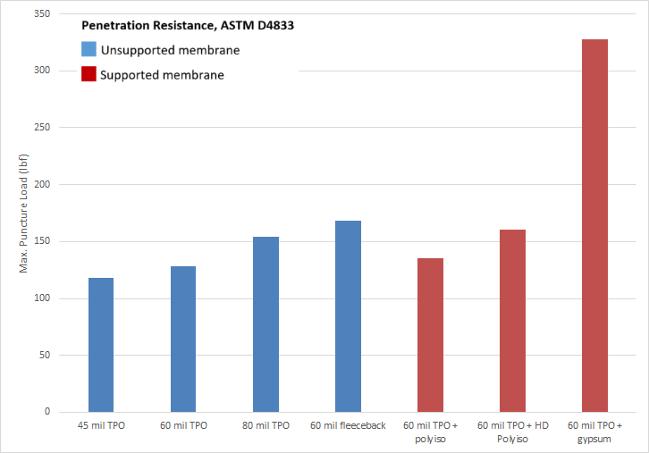
Figure 3: Puncture resistance of varied membrane thicknesses, and with added support of cover boards.
In addition to increased foot traffic, concentrated loads from ballasted PV systems can exceed the compressive strength of the roof system’s membrane and insulation. Specifying a rigid insulation board with high compressive strength, such as an ASTM C1289 Grade 3 polyiso, with a 25psi minimum compressive strength, will distribute loads and help prevent crushing that may occur with lower compressive strength materials.
Design Review
Designers must understand that with the installation of rooftop solar, the roof system becomes a permanent platform for the continuous operation, service, and maintenance of the arrays. As many solar designers may not be intimately familiar with best roofing practices, it is helpful to specify solar layout requirements for rooftop access that align with not only code requirements (i.e., International Fire Code, (IFC) and National Electric Code (NFPA 70)), but with best practices for roof maintenance and safety of rooftop workers. This can include requirements such as prohibiting PV arrays from crossing building expansion joints, and setting PV arrays and rack heights such that the roof membrane seams, drains, and penetrations are accessible for emergency responders and maintenance workers.
Designers and owners also have an opportunity to specify the type of PV attachment, which includes attached, ballasted or adhered. Each option will impact decisions for the roof system design so project teams should take a holistic approach to any value engineering discussions regarding the roof and PV arrays.
As the cost to install PV arrays is significant, specifying an integrity test of the roof membrane prior to installing the solar overburden is a worthwhile investment of time and resources. This could include the incorporation of a metallic primer on the cover board to facilitate electronic leak detection testing, or the installation of a permanent monitoring system, so the owner can continuously monitor for water intrusion, which may be especially useful over critical areas such as uninterruptible power supplies, operating rooms and data storage.
PV Roof System Design: The Real World
While following best practices can result in enhanced long-term performance and minimize designer, owner and contractor risk, not all projects follow these recommendations. As an industry, we regularly see deviations from best practices. These deviations from best practices include, but are hardly limited to:
- Mismatching the expected remaining useful life of an existing roof system with a new PV array installation
- Specifying a 45 mil single-ply membrane
- Installing a mechanically attached membrane and/or insulation boards with adhered or ballasted PV systems
- Eliminating the cover board below the single-ply membrane
- Loose laying the slip sheet below a ballasted PV system
While these modifications may have been made in the name of “value engineering,” understanding the risks associated with these deviations from best practices, and the reduced value they bring to long-term performance may lead to informed decisions rather than decisions based solely on dollars.
A significant risk in PV roof system design is that the life expectancy of the PV system exceeds that of the roof system. Replacing a roof with installed PV arrays may be cost-prohibitive. Therefore, aligning the life expectancy of the roof with the PV system makes financial sense, as well as best roofing practice. For instance, the decision to offset the investment of a PV system by extending the life of an aged roof membrane by the use of a maintenance coating may lead to long term complications and expense t when the PV system needs to be dismantled and reinstalled to facilitate a roof recover or replacement. Worst case scenario? The PV system remains in place on a roof that is no longer protecting the building. Instead of just replacing the roof, the owner may have to also deal with structural repairs, water damage, and mold remediation. Removal and replacement of the PV system, as well as damages incurred to the PV system in the process. This often includes leased PV systems or systems that are simply renting space on the rooftop. In addition, some contract clauses leave the building owner with ownership of the PV system at the end of the lease, which means the building owner is responsible for removing and disposing of the PV system from the roof.
In line with the intent of installing a roof system that exceeds the life expectancy of the PV system, refrain from saving a few pennies by installing a 45-mil single-ply membrane. Best practice is to increase roof membrane thickness to match the service life of the PV arrays. A 60-mil thick membrane should be the baseline design. A good design would include an 80-mil thick membrane. A great design would include a high-performance membrane that has enhanced heat and UV resistance. Again, the risk of installing a thinner single-ply membrane could include the cost of replacing the roof before the PV system needs to be replaced. The cost becomes significantly more than just the cost of a roof due to the cost of dismantling and reinstalling the operational PV system.
Mechanically attaching the roof membrane when installing an adhered or ballasted PV system can result in damage to both the roof and PV systems. The normal billowing during high wind events of mechanically attached roofs could cause ballasted PV systems to shift and damage the membrane. This billowing could also create additional stress on the solar arrays and its connections, compromising the long-term performance and life expectancy of both the roof and the PV system.
Eliminating the cover board from the roof system is sometimes the first step in initial cost savings. The cover board is there to enhance the protection of the roof membrane from the overburden, foot traffic, and maintenance activities. This is especially important with ballasted PV systems that move around on the roof during wind events. A common compromise includes the use of 25 psi top layer of polyiso insulation and standard polyiso insulation installed below. While a cover board can extend the life expectancy of the roof, this approach may be reasonable, specifically for attached or adhered PV systems. However, understand that the puncture resistance of this roof system will be dramatically reduced, putting the integrity of the roof at risk every time maintenance personnel steps onto the roof. Oftentimes tools are inadvertently dropped or a shoe forces a loose object into the membrane (like a piece of gravel or dropped screw). Damage from these instances often go unnoticed until water shows up on the inside of the building. Note that the removal of the cover board for ballasted PV systems is not recommended due to the shifting around of the arrays during wind events, and the resulting repetitive impact on the roof.
Loose laying the slip sheet below a ballasted PV system runs the risk of water collecting between the slip sheet and the roof membrane. Trapped moisture that has no means of evaporation or drainage can have negative long-term effects on some membranes. Additionally, slip sheets could blow away if ballasted PV arrays are lifted up during severe wind events. Adhering the slip sheet to the roof protects the membrane and PV arrays from damage.
Roof Systems Guarantees
The importance of matching the life expectancy of the roof and the PV arrays has been discussed. At a minimum, the roof system must be designed such that the roof system guarantee will meet or exceed that of the PV arrays. Roofing guarantees are a valuable tool for the building owner, but they carry important limitations and conditions that must be addressed for successful rooftop PV installation and operation.
From the start, the roofing system must be designed and installed in accordance with the manufacturers published specifications, and PV system details must be accepted by the manufacturer prior to installation to avoid any lessening of coverage of the guarantee.
Manufacturers typically do not guarantee the solar mount system utilized in the solar installation. Therefore, most manufacturers specifically disclaim any liability arising out of or in connection with the integrity, installation or performance of, or damages sustained by or caused by the roof mount or PV systems. This emphasizes the importance of collaboration between the roof system designer and the PV designer.
PV System Design and Detailing: Best Practices
The layout of the PV system can also influence the long-term performance of the roof. Drainage, equipment access, roof maintenance and safety should be considered, in addition to PV layout and positioning to maximize solar output.
The Port of Los Angeles has a 50-acre bifacial solar array on an industrial facility that collects reflected light from the surface of the roof in addition to direct sunlight, gathering 45 percent more power than traditional designs. The array is expected to produce 565 million kilowatt hours of electricity over 20 years—saving more than 440,000 tons of CO2. This is enough to power 5,000 homes each year and the carbon emission savings are estimated equivalent to taking 6,000 cars off the road. The layout shown in Figure 4 illustrates best practice in terms of PV layout to maximize solar output and provides the necessary walkway paths, fire safety, and access to mechanical equipment and roof drains.
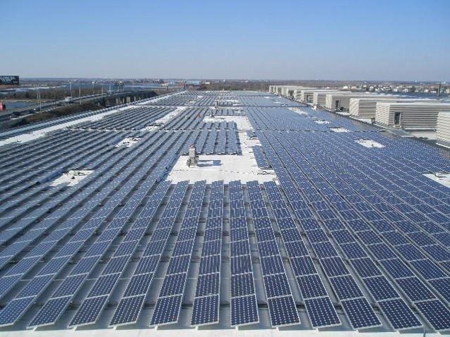
Figure 4: PV layout on the Westmont Industries Distribution Center at the Port of Los Angeles.
Target erected rooftop solar over cool roof membranes on more than one-quarter of its stores, on the way to achieve 100 percent renewable electricity in its stores. The more energy-efficient the roof system performance, the less energy needed to cool stores, and the more sustainable rooftop solar becomes. Figure 5 is the rooftop solar on Target’s distribution center in Phoenix, Ariz. In addition to the clever incorporation of brand in the PV layout, notice the walkway paths and spacing around mechanical equipment. This will facilitate the service and maintenance of rooftop equipment and drains.
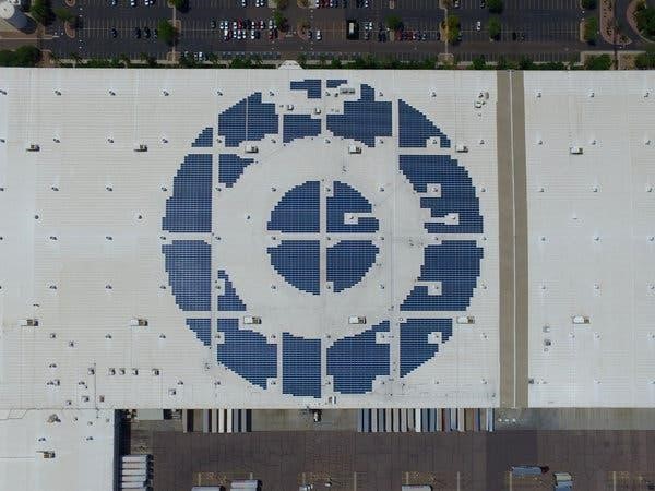
Image courtesy of the New York Times
Figure 5: PV layout on Target’s distribution center in Phoenix, Ariz.
When installing rooftop solar, there are a few important questions to consider.
- Is the life expectancy of the roof system likely to exceed that of the photovoltaic system (PV array)?
- Has the roof system and PV layout been coordinated to facilitate maximum solar output, maintenance and safety?
- What are the potential risks of deviating from best practices to reach a lower cost solution?
This course will explain the importance of each of these questions and offer actionable insights into roof system design that can maximize solar output and provide long-term performance of the roof system that can outlast the life expectancy of the PV arrays.
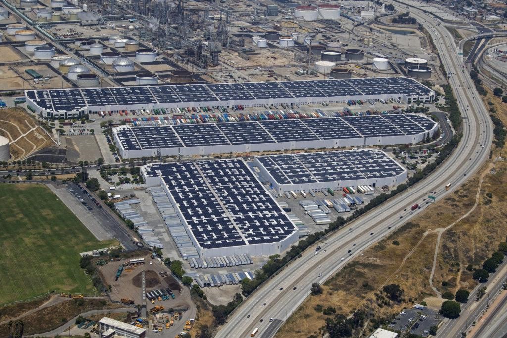
Fifty acres of rooftop solar installed at the Port of Los Angeles.
Introduction
If photovoltaic (PV), aka solar, arrays were installed on all the commercial buildings in the U.S. with roofs over 5,000 square-feet, they have been estimated to provide enough energy to power nearly 60 percent of the total commercial electricity demand. Commercial rooftops are an appealing option as a platform for installing PV arrays to support energy generation, as well as corporate and community energy initiatives. However, it is important to remember that the roof’s primary function is to protect the building and its contents from the elements.
When considering rooftop solar, the roof system should be designed to have an equivalent or longer lifespan than that of the PV arrays. Whether it’s a new roof that has PV arrays or will have PV arrays installed in the near future (i.e., a solar ready roof), or it’s an existing roof that will receive solar, there are many important considerations for roof system design and panel layout.
PV Roof System Design: Best Practices
PV arrays have an average useful economic life of more than 25 years. For commercial rooftop solar, it is often cost-prohibitive to remove existing PV arrays, install a new roof, and then reinstall the PV arrays. Therefore, the best time to install a rooftop PV system is right after a new roof has been installed or when a building has been newly constructed. The key issue is that the roof system should have an expected useful life that matches or exceeds the expected economic life of the PV array. To specify a roof system that is as durable as the PV array, designers should consider the following:
- Adhered reflective roof membranes that provide exceptional protection from weather elements and greater thickness;
- Incorporation of a cover board directly below the membrane to help protect against punctures and damage from rooftop traffic;
- Use of high compressive strength rigid insulation for good traffic resistance and avoid damaged insulation due to the weight of the solar overburden; and
- Roof system warranty or guarantee that exceeds the life expectancy of the PV arrays.
Roof Membranes
By their nature, reflective roof membranes are beneficial in reducing heat build-up around PV arrays as the temperature of a PV panel can significantly impact how much electricity the panel produces, as shown in Figure 1. As panels get hotter, they produce less power. It is estimated that the efficiency of a PV panel can be up to 13 percent higher when installed over a highly reflective membrane compared to a dark membrane with low reflectance. Also, the use of bifacial PV panels over reflective roof membranes can increase the efficiency by 20-35 percent, as they take advantage of the reflected light.
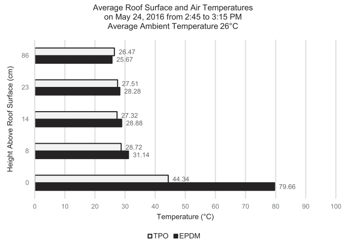
Image courtesy of Architectural Science Review
Figure 1: Average roof surface and air temperatures on a dark absorptive roof membrane versus a cool reflective roof membrane.
The National Roofing Contractors Association (NRCA) recommends the use of a roof membrane that offers enhanced protection against the effects of UV radiation and high service temperatures, and can maintain high reflectance over a long period of time to help ensure that the roof life expectancy will match that of the PV arrays. Figure 2 highlights the advantage of utilizing a membrane that maintains high reflectance over a long period of time. The reflection from the lower roof onto the rising wall can be seen clearly in photographs ranging over a 5-year period. The use of bifacial panels would significantly increase the solar output generated from the use of this highly reflective membrane.
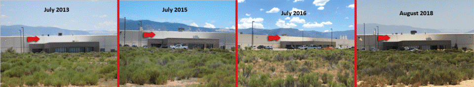
Figure 2: Example of a highly reflective roof membrane (installed on the lower roof) that maintains its reflectivity as it ages.
Designers and owners may also want to consider an increased roof membrane thickness to match the service life of the PV arrays. A large independent study shows an estimated service life of 30-35 years for an 80 mil high-performance TPO membrane, which is in line with high-performance PV arrays and provides some time buffer to have the roof and PV arrays replaced. Additionally, membrane thickness can provide additional protection against punctures, which is especially important considering the extra foot traffic on the roof due to PV service and maintenance activities. Fleece backed membranes installed with a low-rise foam adhesive provide enhanced protection against impact. However, membrane thickness significantly improves impact resistance by almost 80 percent from 45 mil to an 80 mil membrane.
The use of wider rolls, such as 10-foot or 12-foot single-ply membranes, can minimize the number of seams on the roof and reduce the potential for seams to be obscured below PV arrays. This will allow for more thorough roof inspections and future maintenance efforts, should the need arise.
Membrane Attachment
The membrane attachment method should be carefully considered. Adhering the membrane will avoid the normal billowing in high wind events of mechanically fastened single-ply membranes, which could cause ballasted PV systems to shift resulting in localized abrasion of the membrane. The use of a protection or separation sheet installed between ballasted supports and the membrane, extending beyond the contact surface area on all sides, can protect the membrane from abrasion and may be required for warranty or guarantee coverage. The protection sheet should be secured to the roof membrane, not to the bottom of the racking system, so that water does not become trapped between the roof membrane and the slip sheet.
Even if the roof membrane is adhered to the cover board or insulation below, many times mechanical fasteners are below the membrane and attach the cover board and/or insulation to the roof structure. These mechanical fasteners and large metal plate washers are very rigid elements, hidden just below the single-ply membrane. Ballasted PV systems inadvertently placed directly over roof system fasteners may cut or puncture the membrane as the PV array shifts during strong wind events. Burying fasteners in the roof assembly, for example by having the upper layers adhered, will minimize the potential of damage to the roof membrane, as well as enhance thermal performance of the roof system. This supports the use of adhered membranes as well as an adhered top layer of insulation and cover board.
Self-Adhered flexible PV arrays installed over a mechanically attached or induction welded membrane will billow and flutter with the roof membrane during high wind events. Over time, this could create additional stress on the PV arrays, their interface with the membrane, and their electrical connections, and may compromise the solar and roof system performance. Therefore, an adhered roof membrane can contribute to a roof system lifespan that will better match that of the self-adhered flexible PV arrays, and help enhance the performance of both. Of course, it’s necessary to verify material compatibility, long-term durability and heat aging capabilities of the adhesive to the roof membrane and PV arrays, as well as compliance with local code and uplift resistance requirements. For self-adhering PV, use a high temperature-resistant roof membrane as heat collects below these arrays, raising the temperature of the membrane in these locations. Where a standard membrane is utilized, flexible PV should be installed to a sacrificial layer of an adhered roof membrane.
For attached or penetrating systems (i.e. non-ballasted) PV rack mounting systems, mechanically attached or induction welded roof membranes could be more suitable than with ballasted PV systems. Attached PV arrays do not move or shift over the membrane and the array attachment points might act as additional anchors for the membrane. Attached and penetrating systems can be structurally connected to the roof deck below the roof membrane; these connections can be designed to provide robust wind-uplift capacity.
Cover Boards and Insulation
The advantages of greater membrane thickness have been demonstrated. However, roof durability is system dependent so we must look beyond the membrane and consider the entire roof assembly. Rooftops with PV arrays are burdened with more trades and increased foot traffic on the roof, and therefore, are more susceptible to degradation and potential leak sources. A logical starting point is to protect high traffic areas with walkway pads.
The addition of a high-compressive-strength cover board below the single-ply roof membrane will also enhance system protection and extend the life expectancy of the roof. Cover boards provide added protection against penetration by objects, including tools dropped by service contractors, wind-borne debris, and hail. Increasing the thickness of the cover board will increase its penetration resistance. The use of high-density polyiso or gypsum cover boards can significantly increase penetration resistance by nearly 250 percent, as shown in Figure 3.
Figure 3: Puncture resistance of varied membrane thicknesses, and with added support of cover boards.
In addition to increased foot traffic, concentrated loads from ballasted PV systems can exceed the compressive strength of the roof system’s membrane and insulation. Specifying a rigid insulation board with high compressive strength, such as an ASTM C1289 Grade 3 polyiso, with a 25psi minimum compressive strength, will distribute loads and help prevent crushing that may occur with lower compressive strength materials.
Design Review
Designers must understand that with the installation of rooftop solar, the roof system becomes a permanent platform for the continuous operation, service, and maintenance of the arrays. As many solar designers may not be intimately familiar with best roofing practices, it is helpful to specify solar layout requirements for rooftop access that align with not only code requirements (i.e., International Fire Code, (IFC) and National Electric Code (NFPA 70)), but with best practices for roof maintenance and safety of rooftop workers. This can include requirements such as prohibiting PV arrays from crossing building expansion joints, and setting PV arrays and rack heights such that the roof membrane seams, drains, and penetrations are accessible for emergency responders and maintenance workers.
Designers and owners also have an opportunity to specify the type of PV attachment, which includes attached, ballasted or adhered. Each option will impact decisions for the roof system design so project teams should take a holistic approach to any value engineering discussions regarding the roof and PV arrays.
As the cost to install PV arrays is significant, specifying an integrity test of the roof membrane prior to installing the solar overburden is a worthwhile investment of time and resources. This could include the incorporation of a metallic primer on the cover board to facilitate electronic leak detection testing, or the installation of a permanent monitoring system, so the owner can continuously monitor for water intrusion, which may be especially useful over critical areas such as uninterruptible power supplies, operating rooms and data storage.
PV Roof System Design: The Real World
While following best practices can result in enhanced long-term performance and minimize designer, owner and contractor risk, not all projects follow these recommendations. As an industry, we regularly see deviations from best practices. These deviations from best practices include, but are hardly limited to:
- Mismatching the expected remaining useful life of an existing roof system with a new PV array installation
- Specifying a 45 mil single-ply membrane
- Installing a mechanically attached membrane and/or insulation boards with adhered or ballasted PV systems
- Eliminating the cover board below the single-ply membrane
- Loose laying the slip sheet below a ballasted PV system
While these modifications may have been made in the name of “value engineering,” understanding the risks associated with these deviations from best practices, and the reduced value they bring to long-term performance may lead to informed decisions rather than decisions based solely on dollars.
A significant risk in PV roof system design is that the life expectancy of the PV system exceeds that of the roof system. Replacing a roof with installed PV arrays may be cost-prohibitive. Therefore, aligning the life expectancy of the roof with the PV system makes financial sense, as well as best roofing practice. For instance, the decision to offset the investment of a PV system by extending the life of an aged roof membrane by the use of a maintenance coating may lead to long term complications and expense t when the PV system needs to be dismantled and reinstalled to facilitate a roof recover or replacement. Worst case scenario? The PV system remains in place on a roof that is no longer protecting the building. Instead of just replacing the roof, the owner may have to also deal with structural repairs, water damage, and mold remediation. Removal and replacement of the PV system, as well as damages incurred to the PV system in the process. This often includes leased PV systems or systems that are simply renting space on the rooftop. In addition, some contract clauses leave the building owner with ownership of the PV system at the end of the lease, which means the building owner is responsible for removing and disposing of the PV system from the roof.
In line with the intent of installing a roof system that exceeds the life expectancy of the PV system, refrain from saving a few pennies by installing a 45-mil single-ply membrane. Best practice is to increase roof membrane thickness to match the service life of the PV arrays. A 60-mil thick membrane should be the baseline design. A good design would include an 80-mil thick membrane. A great design would include a high-performance membrane that has enhanced heat and UV resistance. Again, the risk of installing a thinner single-ply membrane could include the cost of replacing the roof before the PV system needs to be replaced. The cost becomes significantly more than just the cost of a roof due to the cost of dismantling and reinstalling the operational PV system.
Mechanically attaching the roof membrane when installing an adhered or ballasted PV system can result in damage to both the roof and PV systems. The normal billowing during high wind events of mechanically attached roofs could cause ballasted PV systems to shift and damage the membrane. This billowing could also create additional stress on the solar arrays and its connections, compromising the long-term performance and life expectancy of both the roof and the PV system.
Eliminating the cover board from the roof system is sometimes the first step in initial cost savings. The cover board is there to enhance the protection of the roof membrane from the overburden, foot traffic, and maintenance activities. This is especially important with ballasted PV systems that move around on the roof during wind events. A common compromise includes the use of 25 psi top layer of polyiso insulation and standard polyiso insulation installed below. While a cover board can extend the life expectancy of the roof, this approach may be reasonable, specifically for attached or adhered PV systems. However, understand that the puncture resistance of this roof system will be dramatically reduced, putting the integrity of the roof at risk every time maintenance personnel steps onto the roof. Oftentimes tools are inadvertently dropped or a shoe forces a loose object into the membrane (like a piece of gravel or dropped screw). Damage from these instances often go unnoticed until water shows up on the inside of the building. Note that the removal of the cover board for ballasted PV systems is not recommended due to the shifting around of the arrays during wind events, and the resulting repetitive impact on the roof.
Loose laying the slip sheet below a ballasted PV system runs the risk of water collecting between the slip sheet and the roof membrane. Trapped moisture that has no means of evaporation or drainage can have negative long-term effects on some membranes. Additionally, slip sheets could blow away if ballasted PV arrays are lifted up during severe wind events. Adhering the slip sheet to the roof protects the membrane and PV arrays from damage.
Roof Systems Guarantees
The importance of matching the life expectancy of the roof and the PV arrays has been discussed. At a minimum, the roof system must be designed such that the roof system guarantee will meet or exceed that of the PV arrays. Roofing guarantees are a valuable tool for the building owner, but they carry important limitations and conditions that must be addressed for successful rooftop PV installation and operation.
From the start, the roofing system must be designed and installed in accordance with the manufacturers published specifications, and PV system details must be accepted by the manufacturer prior to installation to avoid any lessening of coverage of the guarantee.
Manufacturers typically do not guarantee the solar mount system utilized in the solar installation. Therefore, most manufacturers specifically disclaim any liability arising out of or in connection with the integrity, installation or performance of, or damages sustained by or caused by the roof mount or PV systems. This emphasizes the importance of collaboration between the roof system designer and the PV designer.
PV System Design and Detailing: Best Practices
The layout of the PV system can also influence the long-term performance of the roof. Drainage, equipment access, roof maintenance and safety should be considered, in addition to PV layout and positioning to maximize solar output.
The Port of Los Angeles has a 50-acre bifacial solar array on an industrial facility that collects reflected light from the surface of the roof in addition to direct sunlight, gathering 45 percent more power than traditional designs. The array is expected to produce 565 million kilowatt hours of electricity over 20 years—saving more than 440,000 tons of CO2. This is enough to power 5,000 homes each year and the carbon emission savings are estimated equivalent to taking 6,000 cars off the road. The layout shown in Figure 4 illustrates best practice in terms of PV layout to maximize solar output and provides the necessary walkway paths, fire safety, and access to mechanical equipment and roof drains.
Figure 4: PV layout on the Westmont Industries Distribution Center at the Port of Los Angeles.
Target erected rooftop solar over cool roof membranes on more than one-quarter of its stores, on the way to achieve 100 percent renewable electricity in its stores. The more energy-efficient the roof system performance, the less energy needed to cool stores, and the more sustainable rooftop solar becomes. Figure 5 is the rooftop solar on Target’s distribution center in Phoenix, Ariz. In addition to the clever incorporation of brand in the PV layout, notice the walkway paths and spacing around mechanical equipment. This will facilitate the service and maintenance of rooftop equipment and drains.
Image courtesy of the New York Times
Figure 5: PV layout on Target’s distribution center in Phoenix, Ariz.
PV Array Layout
The logic behind the layout of PV arrays applies to all attachment options. PV arrays are usually oriented and laid out for maximum solar energy collection. This includes keeping panels away from walls or equipment that provides shading and away from hot air exhaust that will impact PV efficiency. Designers should also consider the appropriateness of PV arrays installed in high-wind uplift pressure areas of a roof, such as corners and perimeters, to avoid potential uplift failures of the PV arrays or the roof system. Arrays should also be configured in such a way to avoid additional snow accumulation.
The layout of PV arrays should also address access for solar installation, PV array and roof maintenance, and fire safety. Safe access for the solar contractors and electricians during installation, as well as service and maintenance over the service life of the PV arrays must be accounted for in the design. This may include davits or other tie-off points, perimeter access and consideration to proximity of overhead power lines. Roof maintenance is also important so PV arrays generally should be kept away from mechanical units, catwalks, anchors, drains and other rooftop elements to provide access for service.
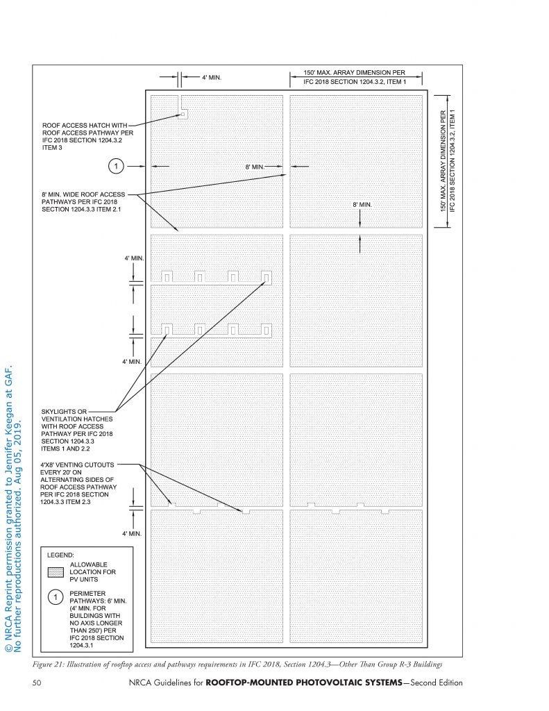
The NRCA Guidelines summarize the requirements from the International Fire Code (IFC) and National Electric Code (NFPA 70). Generally, they require a 4-foot perimeter around roof edges, hatches and a pathway between the two, as well as a pathway along both centerline axes protected by walkway pads or pavers. They also recommend a 4-foot wide pathway to skylights, ventilation hatches and roof stacks for future serviceability, as illustrated in Figure 6. Best practices for fire safety include 8-foot wide pathways for smoke ventilation between panel arrays, and getting approval from the local fire chief.
Roof system maintenance is also an important consideration for PV array layout. It is important to align PV arrays and set rack heights such that there is enough clearance to service the roof membrane, especially drains and penetrations. While a PV layout that covers the entire roof system may maximize solar output, this makes maintenance of both the roof and PV systems nearly impossible (see Figure 7). Considering these panels have a life expectancy in the range of 25 years, these panels need to be cleaned and debris and plant growth that accumulates between panels will need to be removed each year.
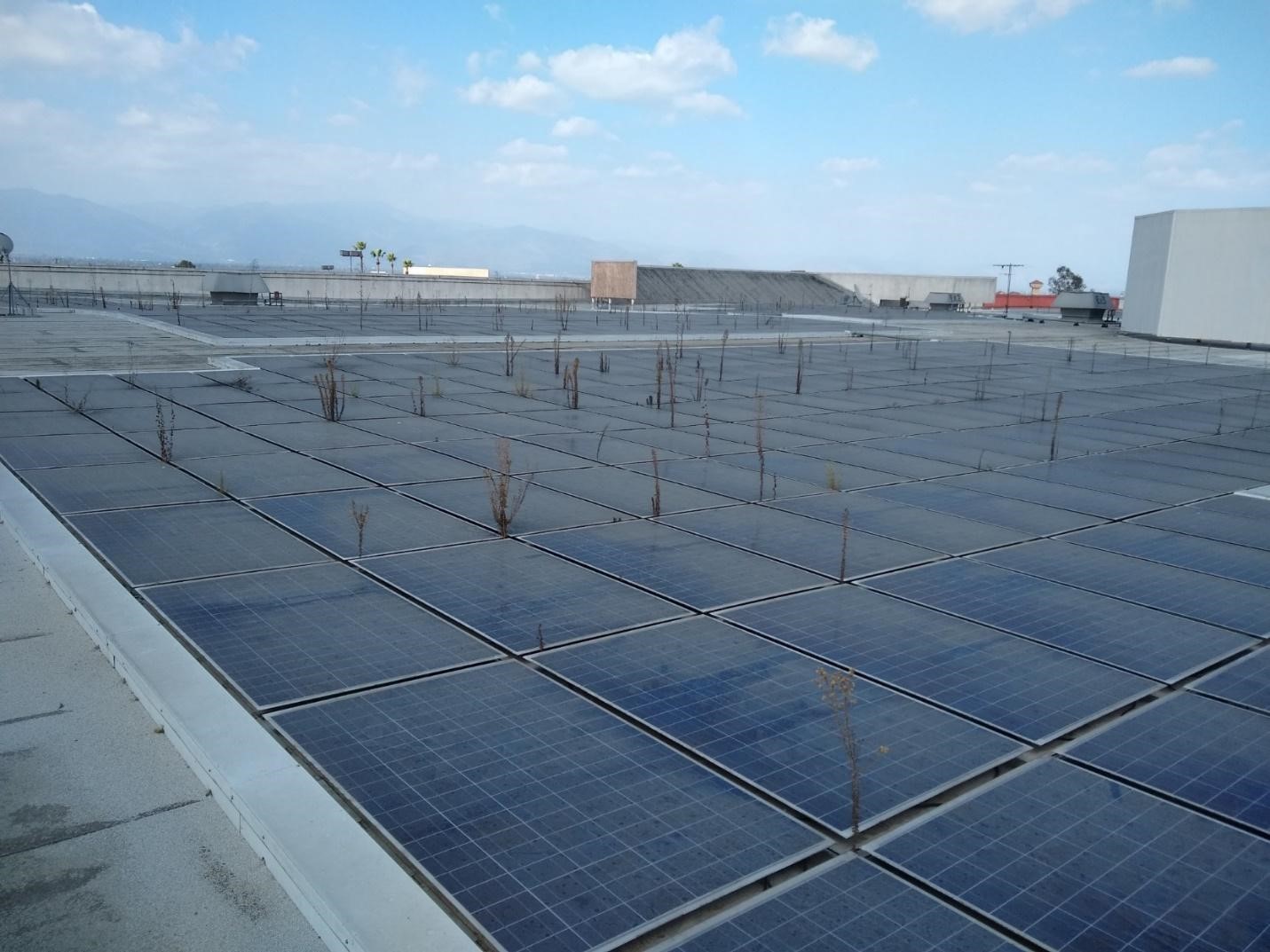
Figure 7: A tightly packed rooftop PV array without space to maintain the panels or the roof.
Providing additional space between the arrays and the roof membrane also increases ventilation and reduces heat build-up, which results in more efficient panels. Some consider that the most efficient PV arrays are installed in conjunction with vegetative roofs, as they provide a better climate and temperature for PV arrays to function, which improves electricity production. The relatively small payback period and the environmental benefits of combining these two sustainable approaches could balance out the initial investment.
Drainage
Installation of a PV system should not interfere with the drainage of the roof system. However, it is not uncommon to see PV arrays covering the roof drains, which significantly hinders access for clearing of debris from the drains. The layout design should consider how the drains will be accessed for maintenance. Adhered PV arrays and ballasted PV systems inherently run the risk of impeding rooftop drainage. Drainage should be considered during the PV layout which is most often specified by a solar designer, not the roof designer. This is just one of many examples of the importance of early project coordination and how critical it is for a successful project.
Consider the following:
- Elevate framing and conduits above the roof surface to allow drainage.
- Install crickets on anything perpendicular to drainage flow and greater than 24 inches wide.
- Projections through the roof system should not be located within 2 feet of valleys or designated drainage areas adjacent to drains, scuppers, or gutters.
- Consider modifying solar racking heights to counter the varying thickness of tapered insulation.
- Review solar array layout such that drainage is not impeded.
- Provide clear access to roof drains and scuppers to allow for maintenance.
Following these drainage best practice guidelines will reduce the potential for ponded and trapped water on the roof, keep the surface cleaner and potentially extend the life of the roof membrane.
PV Array Attachment
Designers have many PV mounting technologies in the market and not all systems are considered equal. It is critical that the designer match the right mounting method with the right roof system. The NRCA recommends the use of attached or penetrating systems, which are mounting systems that are attached through the roof to the structure, as shown in Figure 8. Penetrations and flashings must be well detailed and coordinated with the roofing contractor, solar contractor, and electrician. These details are critical to the success of the installation and must be designed to align with the life expectancy of the PV array and roof system.
Figure 8: Example of attached PV arrays.
Figure 9: Example of ballasted PV arrays.
Image courtesy of Das Energy
Figure 10: Example of adhered PV arrays.
While ballasted PV systems (Figure 9) are cost effective and easy to install, they can add a significant amount of weight to the roof based on the uplift pressures. While this loading can be incorporated into the structural design for new construction, it may exceed the capacity of an existing building. Additionally, concentrated loading of systems beneath the ballast can exceed the compressive strength of the roof insulation. Therefore, the use of a higher compressive strength insulation such as ASTM C1289 Grade 3 polyiso, should be strongly considered. Better yet, consider specifying a cover board such as HD polyiso for added protection.
Ballasted PV systems can shift and flutter and move during high winds and seismic activity. This can result in localized surface abrasion of the roof membrane as it rubs the edges and corners of a PV mounting system which can be “detrimental to satisfactory long-term roof system performance,” according to the NRCA. If the project team accepts the risks associated with ballasted PV systems, a protection or separation sheet should be installed between the ballast supports and the membrane, and should be adhered to the roof membrane via heat welding or with adhesive.
Ballasted trays can block or inhibit drainage, which can result in trapped water on the roof membrane. This can undermine the performance and service life of the roof system. Given all the performance challenges with ballasted PV systems, “NRCA is of the opinion ballasted rack systems do not satisfy the equivalent service life criteria necessary for successful roof system performance throughout the useful life of rooftop-mounted PV systems.” However, as ballasted PV systems are often used, it is important to understand potential issues and use an appropriate design approach with your roof system so the lifespan of the roof can exceed that of the PV arrays.
Another attachment option for PV arrays includes the use of self-adhered flexible panels, which are adhesively applied directly to the roof membrane, as shown in Figure 10. The low-profile application makes this system attractive to many designers, however such panels can expose the underlying membrane to temperatures as high as 195 degrees Fahrenheit. Best practices that extend the life of adhered panels include the use of high temperature-resistant membranes. Where a standard membrane is utilized, self-adhered flexible PV arrays should be installed to a sacrificial layer of membrane. Documented compatibility between the roof membrane and the adhesive is critical. Of utmost concern is the potential for adhered PV arrays to detach from the roof membrane over time as the adhesive ages, and exposure to elevated temperatures and repetitive wind uplift forces.
As previously discussed, adhered PV arrays are best applied to an adhered roof membrane. And given the increased heat load on the roof system with adhered arrays, a roof membrane with enhanced heat aging properties is even more critical.
Thermal Movement
PV arrays and electrical conduits are subject to thermal movement. The expansion and contraction of these elements runs the risk of damaging the roof membrane, premature failure of the PV system, and damage to the electrical connections. The effect of thermal movement may be reduced by:
- Splitting larger arrays into smaller sub-arrays.
- Using racking clips and attachments that accommodate thermal expansion without transferring movement to the underlying roofing systems. Some racking manufacturers have provisions for thermal expansion built into the PV systems.
- Using flexible flashing details for penetrating or attached racking systems.
- Incorporating thermal expansion fittings in straight electrical conduit runs.
- Locating racking systems such that they do not cross over expansion joints.
These strategies apply to all PV systems and can be considered for mounted, ballasted, and adhered systems. Accounting for thermal expansion and contraction is necessary for long-term performance of the PV system.
Racking Systems
The PV racking system should also be designed so that external forces acting on the rack do not compromise the waterproofing integrity of the roofing system. Loads to be considered include horizontal wind load, vertical wind uplift load, vertical dead load, and vertical snow load, as well as vibration loads from external forces or building equipment.
Racking systems should have:
- Thermal and dynamic movement provisions within the racking system.
- Minimal UV exposure of washers/gaskets.
- Base mounts of ballasted PV systems with sufficient area to distribute vertical loads without cutting or compressing the underlying roofing system.
- Support stands fabricated from round steel pipes or square tubes to facilitate effective flashing installation methods in accordance with NRCA or the roof manufacturer’s construction details.
- Ballast pavers that have been tested for long-term durability (for ballasted PV systems), including freeze-thaw durability.
- Compatible corrosion-resistant rack components.
- Sufficient racking clearances for inspection, maintenance, repair or reroofing.
Racking systems should allow ease of removal by trained personnel without exposing the roof system to the possibility of damage. This may require collaboration between the PV system designer and the roof designer to be sure the penetrations are properly flashed and allow for maintenance.
Electrical Connections
Best practice dictates that the number of roof penetrations are kept to a minimum. Cables passing through the roof assembly should not travel horizontally within a roof system, such as directly under the roof membrane or in a notched-out section of the insulation. Adhered PV Systems present unique challenges for cable runs and interconnections. To avoid these issues, consider the use of enclosed electrical conduit that is raised above the roof to facilitate drainage and maintain the integrity of the roof system.
Penetrations of electrical conduit into the building should be properly flashed to the roof system. Electrical conduit passing through a roof assembly should be run inside a sheet metal enclosure with roof curbs. A gooseneck-type penetration detail can be used where a cable needs to pass through a roof assembly and be flashed. All flashings should be installed in accordance with NRCA or the roof manufacturer’s construction details.
Penetration pockets (pitch pockets or pitch pans) are acceptable as a last alternative for flashing PV system electrical connections passing through a roof assembly. Clear access to these penetrations should be provided as more frequent maintenance will be required to maintain the integrity of these penetrations. Again, these flashings should be installed in accordance with NRCA or the roof manufacturer’s construction details.
Installation: Best Practices
The importance of the electrical and solar contractors collaborating in concert with roofing contractors and design professionals cannot be overstated. Qualified roof professionals must be integrally involved through the design process and inspection (and repair as needed) of the roof after solar installation.
As there is a tremendous amount of coordination required to install rooftop solar successfully, it is best practice to specify a pre-job meeting to be held with the building owner, designer, PV system manufacturer, roof system manufacturer, general contractor, electrical contractor, roofing contractor, and any others whose work may have an effect on successful project completion. The PV system designer’s specifications, plans and flashing details should be reviewed during the pre-job meeting. The following items should also be discussed at the pre-job conference:
- Establish construction schedules and work methods that will prevent damage to the PV system flashing and the roof system.
- Establish procedures for reporting and repairing any damage to flashings or any part of the roof system.
- Designate access, staging, work, storage and disposal areas.
- Establish suitable weather conditions and working temperature criteria to which all parties agree.
- Establish safety regulations/requirements and good roofing practices.
- Coordinate the integrity test of the roof membrane prior to the installation of the solar overburden. Retesting the integrity of the roof membrane following the PV system installation may be worthwhile, especially if there was a lot of damage to the roof membrane, there is a permanent monitoring system in place, or the roof is over a critical use area of the building.
- Coordinate the return of the roofer to complete the punch list inspection after the installation of the PV arrays to be sure the roof system has not been inadvertently compromised.
Specifying these requirements will ensure the roof contractor is engaged throughout the entire process, leaving your roof in the proper condition to protect what matters most.
Solar Roof System Design Summary
Clearly, there is a lot to consider when adding PV arrays to the roof. The good news is that as rooftop solar becomes more popular, there are more resources available to designers, owners and contractors to help design, install and maintain a durable roof system that can match or outlast the service life of PV arrays. In summary, best practices for roof system design when considering solar include:
- Roof system design that aligns with or exceeds the life expectancy of the PV array
- Adhered reflective roof membranes with greater mil thickness that provide enhanced protection against the effects of UV radiation and high service temperatures
- Adhered high-compressive strength cover board directly beneath the roof membrane
- High compressive strength insulation for ballasted PV systems (minimum 2 layers staggered and offset)
- Walk pads for high traffic areas
- Proper detailing of attached or penetrating PV mounting systems that are accessible for service
- Protection or separation sheet adhered to the membrane for ballasted PV systems
- Perform design review and construction coordination with the PV designer, roofing contractor, and the solar and electrical contractors
- Integrity testing of the roof membrane prior to installing solar overburden
- Solar layout requirements that align with best practices for roof maintenance
- Layout PV arrays to maximize solar energy collection while avoiding high wind uplift areas and additional snow accumulation
- Provide perimeter and maintenance access for roof and PV array maintenance, as well as fire safety and smoke ventilation
- Set racking systems such that they don’t cross roof expansion joints or block drainage
- Set PV arrays and rack heights such that drains and penetrations are accessible for maintenance
- Engage the roof contractor to inspect (and repair as needed) the roof membrane after PV array installation
- Specify roof contractor engagement throughout the entire process, including punch list inspection post PV system installation
Codes, Standards and Guidelines
Below is a list of references to codes, standards and guidelines relevant to the installation of a solar PV system on a roof. The local Authority Having Jurisdiction (AHJ) should be consulted to determine the specific requirements for code compliance of the solar PV system.
Roof
- ASCE 7-02 Minimum Design loads for buildings (Snow & Wind)
- ICC IBC Wind Resistance—Rooftop PV
- ANSI/SPRI RP-4 Wind Design Standard for Ballasted Ply (Applicable to Ballasted PV)
- UL 1897 Uplift Tests for Roof Covering Systems (Applicable to BIPV)
Design, Installation and Commissioning Best Practices
- NRCA—Guidelines for Roof systems with Rooftop PV Components
- ICC IFC Solar PV Power Systems
- NRCA—Membrane Roof Systems
- NRCA—Metal Panel & SPF Roof systems
- NECA 412 Standard for Installing PV Power systems
Installation
- NECA 412 (201x) Standard for Installing & Maintaining PV Systems
- ICC IFC PV Systems Code Permit Requirements
Module Mounting/Framing
- ICC-ES AC428 Acceptance Criteria for Modular Framing Systems Used to Support PV Modules
- ICC-EC AC286 Acceptance Criteria for Roof Flashing for Pipe Penetrations
- SMACNA - Sheet Metal Manual (For PV standoff/Pipe Penetration)
Fire Rating
- UL 1703 Fire Rating Tests for PV
- ICC IBC Fire Classification of PV
- ICC IEC PV Module Safety
- ASTM E44.44 PV System Fire Safety
- US/ASTM 709/E108 Standard Test Methods for Fire Tests of Roof Coverings
Additional resources available to designers, owners, and contractors alike include the NRCA Guidelines for Roof-Mounted Photovoltaic System Installation, Single Ply Roofing Institute (SPRI) Bulletin on PV Ready Roof Systems, and the Structural Engineering Association (SEAOC) PV manuals for Structural Seismic Requirements and Wind Design.
Resources:
- Photovoltaic Installations Guide
- icap.sustainability.illinois.edu/files/projectupdate/4207/Solar%20with%20Green%20Roof%20design.pdf
- dx.doi.org/10.1080/00038628.2017.1300870
- industry.nrca.net/eweb/DynamicPage.aspx?webcode=NRCAStorePrdDetails&site=nrca&es3_key=4a8483e3-cc27-4724-82bb-fd291153b0c7&prd_key=BFDC8C47-F926-4889-B9B4-38B2016EF45A
- www.spri.org/download/resources_and_education/miscellaneous/SPRI_bulletin_1_13-PV-Ready.pdf
- www.seaoc.org/store/ViewProduct.aspx?id=9173838
- iibec.org/wp-content/uploads/2015-01-bhawalkar-taylor.pdf
- www.gaf.com/blog/science-design/how-to-choose-the-best-membrane-for-a-commercial-solar-power-installation-281474979975989
- www.gaf.com/blog/science-design/solar-power-in-the-desert-or-on-roofs-what-are-the-pros-and-cons-281474979976102
- www.gaf.com/blog/science-design/advantages-of-long-life-roofing-for-bifacial-solar-panels-281474979976109
- www.gaf.com/blog/science-design/value-engineering-part-2-retaining-performance-281474980028033
- www.gaf.com/en-us/for-professionals/resources/tpo-results
- blog.gaf.com/r-value-optimization-a-case-study
Jennifer Keegan, AAIA, has over 20 years of experience as a building enclosure consultant and provides technical leadership within the industry through IIBEC, ASTM, NWIR, and Women in Construction. www.linkedin.com/in/jenniferkeegan