This CE Center article is no longer eligible for receiving credits.
Once a simple hoist mechanism, the dumbwaiter
is now the smart, efficient, safe and economic solution for
moving materials from one floor to another.
Since the late 18th century when Jefferson adopted the French
custom of using several of them for dinner parties, the dumbwaiter
has joined our lexicon. It has saved labor and efficiently
solved the eternal challenge of moving objects from one floor
to another. But dumbwaiters of the twenty first century are
a far cry from those hand-crafted European devices. For one
thing, Jefferson's dumbwaiters, while certainly silent, did
not move. Different from the wine elevators he installed on
both sides of Monticello's dining room fireplace that led
directly to the wine cellar below, they were small free-standing
tables whose several shelves held food, dishes and silver.
Placed beside each guest, they replaced curious servants or
slaves and were intended to encourage free and unrestricted
conversation. Another difference is that today's dumbwaiter-despite
its name-is smart, a significantly less costly alternative
to the elevator, employs state of the art technology and promotes
safety. While the elevator has generated a body of knowledge-it
even has its own online museum-the dumbwaiter has been
virtually ignored despite its long-time use in a multitude
of building types.
Over the years, the dumbwaiter has lent its name to a group
of products known as vertical materials handling systems-systems
that have proven adaptable to any situation in which goods
of any kind-but not people-are moved from floor
to floor in multi-story buildings.
Promoting Economy, Safety and Efficient
Use of Space
It "saves miles of steps for busy feet," announces
a 121-page brochure from a former Chicago dumbwaiter manufacturer
dated 1914. Inside are abundant photographs of virtually every
major hotel, club, hospital, restaurant, department store
and office in the country that had acquired one of its electrified
systems. The company added the cogent argument that its system
also saved money, "don't waste the valuable time of high
priced help in running up and down stairs with goods."
While the cost of help in 1914 must appear ludicrously low
in today's dollars, the point is particularly relevant
today. Dumbwaiters create payback efficiencies. Passenger
elevators are not tied up with the transportation of materials
and can therefore accomplish the purpose of moving people
quickly and efficiently. Since they do not need to walk around
or up and down stairs delivering materials along with obligatory
pleasantries, employees are able to stay in their offices
and their workstations. The calculation of a hypothetical
situation makes a striking point. If ten employees whose average
salary and benefits amount to $35 per hour make three 20-minute
trips per day, the cost to their employee is $3,500 per week.
Safety is another benefit. With the appropriate choice of
product, employees avoid dangerous misuse of equipment such
as fork lifts and chain hoists. Employees pushing, pulling,
carrying and lifting often cause accidents, falls, bumps and
injuries. In addition to time lost through hours and days
off, there are additional costs incurred in related paperwork,
reports and possible litigation. The Bureau of Labor Statistics
reports that in 2003, sprains and strains accounted for 43
percent of injuries resulting in days away from work in the
private sector- evidence that appropriate materials handling
positively contributes to safety and welfare for all partiesDumbwaiters
also save space and cost less than their alternatives. Depending
upon configuration and the type of lift, initial total installed
costs are approximately 40 percent to 60 percent less than
that of a passenger or freight elevator. In terms of square
footage of a building floor plan, they require 50 to 75 percent
less than that taken up by an elevator. This translates into
significant useful space that can be allocated to the original
purpose of the building. They also have both a long life and-at
25 years-a long modernization cycle.
Different Types of Systems: Dumbwaiters
There are two major groups of vertical material handling
systems: dumbwaiters and conveyors.
Dumbwaiters are restricted
in size of platform (10.75 square feet) and clear inside height
(4-feet). Code regulations state they must have a minimum
capacity of 13.9 lbs. per cu. ft of internal area, but no
maximum capacity; they are, however, generally built with
a capacity of 100 lbs. to 500 lbs. They are usually enclosed
within a fire-rated hoistway or shaft and equipped with fire-rated
hoistway entrances. They can be equipped with power operated
hoistway entrances and automatic loading and unloading conveyors
at landings. They can also stop at floor level for the transport
of wheeled carts or at table or counter height for hand loading.
Dumbwaiters are allowed by code to have machines within and
adjacent to the hoistway. They are regulated by the elevator
code (ANSI 17.1).
Depending upon requirements of speed, capacity and travel
distance, dumbwaiters use one of two types of hoisting mechanisms:
winding drum and traction. Thewinding
drum dumbwaiter raises and lowers the car by wrapping
and unwrapping the hoist rope on cylindrical steel grooved
drum located at the top or bottom of the lift shaft.
- Ideally suited for heavy-duty use in medium or low-rise
applications.
- Maximum speed of 50 feet per minute.
- Capacity is usually 100 lbs. to 500 lbs.
- Height limitation is usually 50 feet. Larger travel distances
are possible with custom design.
- Space required above the car at upper landing usually
varies between 42-inches and 60-inches if the machine is
located at the top. Space required at upper landing if the
machine is located below depends upon the height and type
of entrance door used.
- Car dimensions can vary according to client needs.
- Machines for floor loading dumbwaiters are mostly located
at the top, but in some situations such as clean rooms,
can be located at lower landings adjacent to and at the
sides of the hoistway. Machines for counter-height loading
dumbwaiters may be located inside the hoistway and below
the counter-height.
- Its heavy-duty guide rails can span 12-feet floor heights
without requiring intermediate brackets or tower support,
allowing the use of lightweight, non-load bearing shaft
walls.
- Hoistway clearances (see diagram A)
- An ideal choice for adding onto existing structures.
- The least expensive system with minimal maintenance.

Winding Drum Dumbwaiter |
|
|
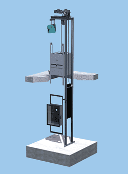
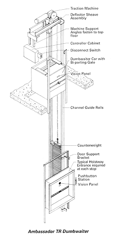
Thetraction dumbwaiter machine,
commonly located at the top of the lift shaft, turns a pulley
called a traction sheave. Hoist cables run over the top of
the sheave and drop on one side to the car and on the other
side to a counterweight. When the car goes up, the counterweight
goes down, and vice versa. The use of a counterweight allows
less energy to be expended.
- Usually used in higher rise and higher speed applications.
- Speed is 50 to 300 feet per minute.
- Capacity is usually 100 lbs. to 500 lbs., but can accommodate
more.
- Machines are mostly located at the top, but, in some situations
such as clean rooms, can be located at lower landings adjacent
and at the sides of the hoistway.
- Space required above the car at upper landing varies
between 48-inches and 66-inches.
- It offers floor-level loading or counter-height loading
capability.
- Hoistway clearances (see Diagram A)
- Counterweighted traction design employs high-rise
elevator technology. State of the art microprocessor
controls allow custom programmed operations.
- More expensive than winding drum or hydraulic systems.
The most valuable benefit of dumbwaiter systems is their
seemingly never-ending usefulness in today's many building
types. Found in restaurants, universities, clinics, hotels,
hospitals, libraries, office buildings, warehouses, retail
stores, clean room manufacturing, laboratories, airports,
banks and courthouses, they can be configured for file distribution
and trendy sportswear showrooms to prisons and four-star restaurants.

Winding Drum Dumbwaiter |
|
|
Sometimes they serve as a simple inexpensive substitute for
an elevator. DiMarinisi & Wolfe Architects and Urban Designers
designed a new state police station in Dartmouth, MA. The
many boxes of documents and files were to be stored in the
attic of the single story building. Options for transporting
them included an elevator or a dumbwaiter. Since there was
no need to transport people to the attic, partner Maury Wolfe,
AIA, specified a dumbwaiter.
At other times they offer a simple solution to a design problem.
For the expansion and renovation of the Dana Athletic Center,
Bentley College, Waltham, MA, Jeffrey Millman Associates with
Add Inc created a formal dining room on the second floor above
the main dining space and kitchen. The problem was how to
transfer the food from the kitchen to the satellite serving
space above. The footprint was small and the existing elevator
conveniently near the fitness area. So rather than relocate
the elevator, reports project manager KyAnn Anderson of Add
Inc, the team chose to send out a preconstruction bid for
a dumbwaiter.
Traction Dumbwaiter |
|
|
Other situations require new ways of solving old demands.
During its fifteen years of working on eighty-plus court related
projects, Moselely Architects of Richmond, VA, was frequently
asked to install a pneumatic tube system (PTS). Used for delivering
documents, a PTS requires an air compressor and 4-inches or
greater tubing diameter bent in radiuses of approximately
48-inches. In recent years there have been fewer requests
for a PTS, reports senior associate Ronald D. Crouch, AIA.
With the greater use of computers and digital scanning, documents
could be retrieved easily on screen. But when Moseley undertook
the renovation and expansion of the Juvenile and Domestic
Relations Court in Charlottesville, VA, the experienced clerk
of the court asked for a document transfer system. Judging
by the size of the sample documents, the 4-inch PTS tube was
not large enough. Instead, the firm specified a dumbwaiter-for
the first time, Crouch believes.
Selecting one with a winding drum mechanism-the smallest
and simplest available-the firm created a gypsum wallboard
type shaft, which required code compliance just as with a
stair or elevator application. Since the old wood flooring
was being replaced, there was minimal impact on the structural
design of the floors. Because access to the machine was placed
at the lowest level opening instead of above the car, a fire
rated access door was required. Crouch points out the importance
of having the controls and bottom of the opening accessible
for people with handicaps.
|
Dumbwaiter Speeds,
Capacity and Travel Limitations
|
System
|
Speed
|
Capacity
|
Travel Limitation
|
Code
|
|
Winding Drum dumbwaiter
|
50 f.p.m.
|
Up to 500 lbs.*
|
50 feet*
|
elevator
|
|
Traction dumbwaiter
|
50 to 300 f.p.m.
|
Up to 500 lbs.*
|
None
|
elevator
|
| *
Larger capacities and travel distances are possible
with custom design. |
|
The Planning Process
While each project is unique, the planning process for specifying
dumbwaiter systems includes the same key decisions. There
is a logical order to the process, but building constraints
such as the space available above the car on the upper landing,
may dictate the choice of lift. Fortunately for those familiar
with the former MasterFormat numbering system, there is little
new to learn in the new MasterFormat 2004 Edition. All Conveying
Equipment remains in Division 14 with Conveying Equipment
assigned to 14 00 00 and Dumbwaiters assigned to 14 10 00.
Traction Dumbwaiter |
|
|
The planning steps are:
- Determine whether the dumbwaiter will stop at floor level
or counter height.
- Note hoistway or shaft clearances (Diagram A).
- Determine space requirement above the car at the upper
landing.
- Determine the limitations of travel and speed according
to the project requirements.
A rule of thumb for selecting speed requirement for medium
and high-rise applications: the traveling time between terminal
landings should never exceed 30-45 seconds.
On speeds exceeding 100 feet per minute, variable voltage
equipment will often be required.
- Determine whether guide rails should be bracketed to the
walls and floor slabs (required load-bearing or reinforced
hoistway walls) or furnished with a full, self-supporting,
angle tower, permitting use of less expensive wall construction.
(Most local building codes require shaft walls to have a
two-hour fire rating.)
- Determine machine location. Traction dumbwaiter machines
are usually located at the top. Machines for winding drum
floor loading dumbwaiters are commonly located at the top,
but with a counter-height loading model, they may be placed
in the hoistway below the counter-height. In special situations
such as clean rooms, machines for both winding drum and
traction type dumbwaiters may be located at lower landings
at either side of the hoistway
- Select lift model.
Example of specifications for traction dumbwaiter
Part 1 - General 1.1
Section Includes
A. Furnish and provide all
materials and labor necessary for the complete installation
of one commercial traction dumbwaiter.
B. Obtain information on conditions
affecting work at jobsite, including verification of dimensions,
field material for anchoring, accessibility and storage space.
Verify voltages and outlets on electrical drawings.
Diagram
A
Approximate hoistway or shaft dimensions for
drum and dumbwaiter installations
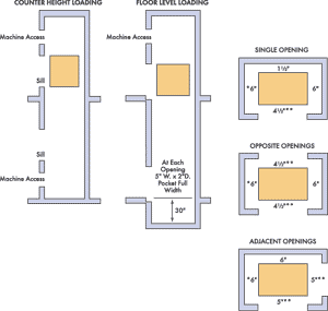
* 2-inches additional
side to side clearance required with self
supporting tower.
** If doors and gates are power-operated 1/2-inch
additional depth clearance is required at
each car opening.
*** Consult supplier for shallow pit requirements. |
|
|
1.2 Work Done By Others
A. Suitable, legal, two-hour
fire rated hoistway, if consistent with building construction.
B. Hoistway door walls must
not be erected until doors are set in place.
C. Electrician shall furnish
power supply with line disconnect switch immediately adjoining
the controller cabinet.
D. Hoistway free of all pipes
and obstructions.
E. All bracket fastening inserts
and other steel required for support of guide rails and brackets.
F. Painting of exterior walls
and prime finished components which are exposed to view, including
inside of car, car gates and doors.
G. Machine area lighting and
convenience outlet.
1.3 References
Design and installation shall be in compliance with regulations
and all governing agencies. Lift shall be subject to local,
city and state approval prior to installation, along with
city and state inspection after installation. Special local
requirements shall be determined and handled locally by distributor
with manufacturer's agreement.
1.4 Submittals
Submit drawings or manufacturer's literature for approval.
Drawings shall show rough-in requirements and wiring materials.
1.5 Substitutions
No substitutions will be considered unless written request
for approval has been submitted by the bidder and was received
by the architect at least ten (10) days prior to the date
of receipt of bids. Each such request shall include the name
o the materials for which it is to be substituted and a complete
description of the proposed substitute including drawings,
cuts, performance and test data, a list of projects of similar
scope, photographs of existing installations and any other
information necessary for evaluation.
1.6 Testing
The dumbwaiter shall be tested after installation to demonstrate:
- Accuracy of stops
- Operation of hoistway door locks and car gate switch
(es).
- Operation of final terminal switches
- Operation of push-button and key switches
- Capacity load test. Operate dumbwaiter for a period of
twenty (20) minutes with a capacity load. Run dumbwaiter
from top terminal floor to bottom floor with one minute
between starts after each stop.
PART 2 - PRODUCTS
2.1 Manufacturer
Name of manufacturer
2.2 Product Type
A. Model shall be the commercial
traction dumbwaiter
B. Car shall have clear inside
dimensions of ________ inches wide x _______ inches deep x
________ inches high, and have one removable shelf. Capacity
to be ________ pounds. Dumbwaiter to serve _______stops and
___________ openings, located on ( ) same, ( )opposite, (
) adjacent side(s) of the hoistway. The car shall stop at
( )counter-height or ( ) floor level. The travel distance
shall be ____________ feet. Power supply shall be _______volt,
3 phase, ___________ hertz.
C.All equipment shall be manufactured
in accordance with the latest edition of the ANSI 17.1 code
for elevators, escalators, and dumbwaiters.
2.3 Fabrication
A. Car Enclosure: The car shall
be constructed of 16 gauge ( ) #4 satin polished stainless
steel or ( ) carbon steel with a prime finish. Car shall have
one removable shelf. An electrical light fixture shall be
recessed in the ceiling. Floor loading models shall have a
reinforced floor.
B. Car Gates: The car shall
be equipped on each open side with a gate matching the car
construction and finish. The gate shall be vertical ( ) bi-parting
or ( ) slide up design. Car gate(s) shall be manually operated
unless power operation is specified.
C. Guide Rails: Steel channel
rails 2 7/8"wide x 1 3/4" deep and 1/4" flange
shall be furnished to guide the car. Guide rails shall be
mounted to the floor slabs and hoistway wall with steel brackets.
D. Machine: Machine shall be
the traction type. Motor shall be of ample horsepower to lift
the rated load at the rated speed, with a high starting torque
and low starting current. It shall be equipped with a spring
applied and electrically released brake. Machine shall be
located at the top of the hoistway and mounted on structural
steel base. The traction sheaves shall be semi-steel, with
machine grooves designed to provide adequate traction, and
long cable life.
E. Controller: Controller shall
be wall mounted type with lockable door, located on hoistway
outer wall in sight of machine access door. Controller shall
be solid state programmable and Underwriter's Laboratories,
Inc. listed.
F. Operational Control: Operation
shall be automatic call and send. A pushbutton station with
one button for each level served, shall be furnished at each
door. It shall be possible at each level to call the car or
send it to any other level. Pushbuttons shall be inoperative
while car is in transit, and for a few seconds after arrival
at the selected level. Pushbuttons shall have stainless steel
faceplates.
G. Signals Devices:
- "Door Open" call buzzer shall sound when a pushbutton
is pressed and a hoistway door or car gate is open.
- "Car Here" light and chime - shall be located
in each pushbutton station. Chime shall indicate car arrival.
Light shall indicate car presence.
- Combination "Door Open" and "In-Use"
light - shall be located in each pushbutton station. Light
will illuminate when car is in transit and when a pushbutton
is pressed and a hoistway door or gate is open.

Traction Dumbwaiter |
|
|
H. Leveling Accuracy: If the
car stops above the floor level, car floor shall be no more
than 1/2" above or below the level of the hoistway door
sill. If car stops at floor level, car floor shall be no more
than 1/4" above or below the level of the hoistway door
sill.
I. Hoist Ropes. Minimum (2,
1/4" x 3 x 19) traction steel cable with safety factor
per code.
J.Final Limit Stopping Devices:
Provide per code
K. Guide Shoes: Guide shoes
shall be adjustable, renewable dry type.
L. Hoistway Doors: Door shall
be vertical sliding ( ) bi-parting or ( ) slide up design.
Each door shall bear the Underwriters "B" label
and shall be rated for application in;(a) masonry shaft or
(b) metal stud drywall shaft. Hollow metal door panels shall
be 16 gauge ( ) stainless steel with satin polish & No.
4 finish or ( ) carbon steel with prime finish. Welded unit
wall frame, including jambs, trim and sill shall be; 16 gauge
( ) stainless steel with satin polish & No. 4 finish or
( ) carbon steel with prime finish. Doors shall be manually
operated unless power operation is specified. A door lock
and contact shall be provided on each door.
M. Machine Access Door: Hinged
access door shall be 24" w x 24" h and shall be
furnished at machine location for service and maintenance.
Access door shall be 16 gauge ( ) stainless steel with satin
polish & No. 4 finish or ( ) carbon steel with prime finish.
N. Counterweight: The counterweight
shall be equal in weight to that of the car plus 40% of the
rated capacity.
O. Drawbridge (Optional): Floor
loading models with bi-parting door and car gates shall be
equipped with drawbridge to provide smooth entrance for wheeled
carts. Drawbridge shall be raised and lowered by opening and
closing of car gate.
P.Self-Supporting Tower (Optional):
Components shall be carried on a self-contained, rigidly braced,
structural steel angle tower. Tower must be braced by building
structure.
Q. Power-Operated Hoistway
Doors and Car Gate(s) (Optional): Car gate(s) shall be motorized,
and shall be equipped with magnetic clutch assembly which
shall power operate the hoistway doors.
A. Rated load _________ pound
capacity
B. Minimum travel speed shall
be _________________ F.P.M
- If rated speed is 50 F.P.M. drive and control shall be
single speed A.C.
- If rated speed exceeds 50 F.P.M., drive and control shall
be variable voltage, variable frequency A.C.
C. Leveling Accuracy: Car floor
shall be no more than 1/2" above or below the level of
the hoistway door sill.
Part 3 - Execution 3.1
Installation
A. Coordinate work with General
Contractor.
B. Leave standard electrical
connection drawings with electrical contractor to make final
electrical connection. Wiring within unit shall be done as
part of work of the is section, 20 amp circuit required.
C. The installation of the
dumbwaiter shall be made in accordance with the approves plans
and specifications and manufacture's installation instructions
Different Types of Systems: Vertical
Reciprocating Conveyors
Vertical reciprocating conveyors are vertical lifts designed
for large scale, higher-speed delivery of heavy or bulky materials
(the term ‘reciprocating' indicates that the conveyor
moves up and down). They can be utilized in either commercial
or industrial applications but cannot be exposed to or used
by the general public. In commercial buildings a conveyor
is usually contained within a fire-rated shaft with fire-rated
hoistway entrances. In industrial applications it is often
protected by sheet metal barriers, which have no fire rating.
Conveyors are regulated by ASME B.20.1 safety standard.
- Virtually unlimited travel distance.
- Speeds up to 300 feet per minute.
- Load capacity up to 2000 lbs.
- Platform size up to 52-inches x 52-inches.
- Loads from floor or platform height.
- Can be manually loaded or installed with optional transfer
device for automatic load/unload, or for interfacing with
automated material handling systems.
- Options include carriage enclosure; power-operated guard
doors; touch screen control module.
- Self-supporting.
- Modular construction.
Conveyors may be specified with aroped
hydraulic lift equipment for low speed and medium rise
applications. They offer the least expensive means to raise
heavy loads and the design advantage of having a machine that
is located outside but adjacent to the hoistway at the rear
or side of the car. The hydraulic system works by pumping
oil into a cylinder, which causes a jack to rise. Stationary
cables attached to the car pass over the sheave on top of
the jack. When the jack rises, the cables hoist the car and
vice versa. Unlike a direct action hydraulic system, no deep
hole is needed to sink the hoistway at the rear or side of
the car. Hydraulic lifts costs are in the medium range.
Diagram
A
Approximate hoistway or shaft dimensions
for drum and dumbwaiter installations
 Notes
1. Lift supporting structure is connected
to the building at the loading levels for
stabilization.
2. Overhead requirements vary depending
on equipment furnished. Certain options
can have a substantial impact.
3. Minimum loading height at the lower level
can vary due to model or options chosen.
Consult supplier for nominal height.
4. For Floor Loading conveyors loading height
can be level with floor if a pit is provided.
5. With Above Floor Loading the driving
machine may be located below the door entry.
|
|
|
|
|
Conveyors present a cost effective solution to providing
access to all levels of a building by requiring minimal floor
space. They have been used for manufacturing, warehousing,
distribution, food processing, mezzanine lifts and pallet
lifts. In addition to their application across a broad range
of commercial and industrial sectors, they offer a number
of configurations for different functions.
Their advantages include:
- Expendable, reprogrammable equipment.
- Open or enclosed load platform.
- A wide variety of enclosures.
- May be configured for use in sanitary settings such as
hospital food service, sterile supply environments and clean
rooms.
- Optional fire rated access doors and UL rated controls.
Different Types of Systems: Vertical
Material and Cart Handling
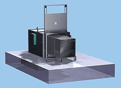
Vertical material and cart handling systems are designed
for large scale, high-speed delivery of heavy or bulky materials
and can be designed for low, medium, or high-rise applications
that need to make high-speed transfers. Carts may be manually
loaded or provided with automatic loading and unloading equipment.
They are powered hydraulically, by winding drum, or by traction,
and are regulated by either conveyor safety ASME B.20.1 or
ASME 17.1 elevator code.
- Doors can be manually operated swing type, power, or
manually operated vertical bi-parting type hoistway doors.
- Car sizes up to 36-inches wide x 72-inches front to back
x 80-inches high.
- Fire-rated hoistway, pit, and machine room required for
some applications.
With either open or enclosed load platforms, cart systems
may be configured for use in sanitary applications, hospital,
food service, sterile supply environments, clean rooms. surgical
carts, supply carts, manufacturing, laundry, food service
and bulk handling.
|
Table of Dumbwaiter
Speeds-Capacity-Travel
|
System
|
Speed
|
Capacity
|
Travel Limitation
|
Code
|
|
Hydraulic material
lift
|
30 f.p.m.
|
Up to 1000 lbs.
|
40 feet
|
elevator
|
|
Traction material lift
|
100 f.p.m.
|
Up to 1000 lbs.
|
none
|
elevator
|
|
Hydraulic vertical conveyor
|
30 f.p.m.
|
Up to 1000 lbs.
|
40 feet
|
conveyor
|
|
Traction vertical conveyor
|
100 f.p.m.
|
Up to 1000 lbs.
|
none
|
conveyor
|
|
Winding drum vertical conveyor
|
30 f.p.m.
|
650 lbs.
|
40 feet
|
conveyor
|
|
They also offer a convenient means for achieving the best
use of prime space. When the Gould Tanner Group of Nashville
embarked on an addition and renovation for the Bayshore Medical
Center in Pasadena, Texas, it needed to expand outpatient
surgery and add operating rooms on the first floor. In the
existing footprint, central sterile was also on the first
floor, a convenient cart trip away from the operating rooms.
In order to locate the new surgery rooms on the first floor,
explains Matt Rigsby, AIA, project coordinator, central sterile
needed to be moved. The solution was to put it in the basement
and use two sets of cart handling systems to deliver and fetch
the clean and dirty materials. Although the distance was just
one floor, traction motors were specified for faster speed.
Different Types of Systems: Automatic
Delivery
An alternative to manual distribution, automatic delivery
dystems handle small loads 100 lbs. or less and are cost effective
because there is no loading, unloading or waiting. They are
used to handle pharmaceuticals and patient files in hospitals,
mail and file distribution in offices, and inventory and file
distribution in manufacturing facilities. Automatic systems
employ either dumbwaiter or conveyor technology depending
upon travel and speed requirements. The automatic dumbwaiter
is regulated by elevator code (ANSI 17.1). Exempt from elevator
code, the automatic conveyor is regulated by conveyor code
(ASME B20.1)
Vertical Material
and Cart Handling System |
|
|
- Speed from 50 to 300 feet per minute
- Capacity 100 lbs. or less
- Travel limitation none.
- Easily installed in new and existing structures
- Requires minimal floor space.
- Loads may be simultaneously dispatched from and sent to
any user station.
- Can be expanded and reprogrammed to meet changing material
flow requirements.
Example of specifications for vertical reciprocating conveyor
(with winding drum mechanism).
PART 1 - GENERAL
1.1 Section Includes
A. Furnish and provide all
materials necessary for the complete installation of one (manufacturer)
Vertical Reciprocating Conveyor.
B.Obtain information on conditions
affecting work at jobsite. Including verification of dimensions,
field material for anchoring, accessibility and storage space.
Verify voltages and outlets on electrical drawings.
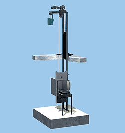
Automatic Delivery
System |
|
|
1.2 Work Done By Others
A. Electrician shall furnish
a properly protected power supply of sufficient capacity.
B. Provide support and bracing
for the framework and enclosure.
1.3 References
Design shall be in compliance with the A.S.M.E. B.20.1 standard.
Special local requirements shall be determined and handled
locally by dealer with manufacturer's agreement.
1.4 Submittals
Submit drawings or manufacturer's literature for approval.
Drawings shall show equipment dimensions and clearance requirements.
|
Chart for Automatic
Delivery Systems
|
System
|
Speed
|
Capacity
|
Travel Limitation
|
Code
|
|
Automatic
dumbwaiter system
|
50 to 300 f.p.m.
|
100 lbs.
|
none
|
Elevator
ANSI 17.1
|
|
Automatic conveyor system
|
100 f.p.m.
|
100 lbs.
|
95 feet
|
Conveyor
ASME B20.1
|
|
1.5 Substitutions
No substitutions will be considered unless written request
for approval has been submitted by the bidder and was received
by the specifier at least ten (10) days prior to the date
of receipt of bids. Each such request shall include the name
of the materials for which it is to be substituted and a complete
description of the proposed substitute including drawings,
cuts, performance and test data, a list of projects of similar
scope, photographs of existing installations and any other
information necessary for evaluation.
1.6 Testing
The conveyor shall be tested after installation to demonstrate:
- Accuracy of stops
- Operation of door locks
- Operation of push-button and key switches
- Capacity load test
- All safety devices and circuits are functional.
PART 2 - PRODUCTS
2.1 Manufacturer
Name of manufacturer
2.2 Product Type
A. Model shall be the (name
of product). The Vertical Reciprocating Conveyor shall consist
of a structural steel framework complete with machined vertical
steel guide rails and expanded metal guard barriers at each
landing to 8 feet high on all sides. The structure shall support
a winding cable drum machine at the top. Overall lift capacity
shall be ____ lbs. The carriage shall have platform dimensions
of ___ inches wide x ___ inches front-to-back. The loading
height of the carriage enclosure shall be ___ inches. Conveyor
to serve ____levels and_____ openings, with a ( ) configuration
or a ( ) configuration. Stops will be at ____ inches above
the floor level. The travel distance shall be _____ feet _____
inches. Power supply shall be _______volt, 3 phase,_____ hertz.
B. All equipment shall be manufactured
in accordance with the latest edition of the National Electrical
Code and A.S.M.E. B.20.1 code for Conveyors and Related Equipment.
2.3 Fabrication
A. Carriage: The carriage shall
be of fabricated steel construction.
B. Guide Rails: Precision machined
steel rails shall be furnished to guide the carriage.
C. Machine: Machine shall be
the winding drum type mounted on a steel frame at the top
of the structure. Motor shall be of ample horsepower to lift
the rated load at the rated speed. It shall be equipped with
a spring applied and electrically released brake. The drum
shall have precision machined grooves designed to provide
long cable life.
D. Controller: NEMA 12 Controller
enclosure shall be equipped with lockable door and electrical
disconnect. Controller shall be solid state, programmable
and Underwriter's Laboratories, Inc. listed.
E. Operational Control: Operation
shall be automatic call and send. A pushbutton station wit
one button for each landing served shall be furnished at each
door. It shall be possible at each landing to call the car
or send it to any other landing. Pushbuttons shall be inoperative
while car is in transit and for a few seconds after arrival
at the selected landing.
F. Leveling Accuracy: Carriage
platform shall be no more than _" above or below the
landing door sill.
G. Hoist Ropes. Provide aircraft
type steel hoist cable with a minimum 7:1 safety factor.
H. Entrance Guard Doors: Doors
shall be vertical sliding bi-parting or single panel slide-up.
Each door shall be equipped with an interlock to prevent the
carriage from moving unless the door is closed and locked.
Metal door panels shall be expanded metal.
I. Manuals: Provide required
instruction manuals, diagrams and parts lists necessary for
operation and maintenance of system.
2.4 Performance
A. Rated load ____lb. capacity
B. Travel speed shall be ____
F.P.M.
2.5 Options
A. Fire Rated Entrance Doors:
Entrance doors shall bear the Underwriter's Laboratory
"B" label and shall be rated for installation in
masonry or stud and drywall shaft.
B. Power Operated Entrance
Doors: Entrance doors shall be power operated. The door shall
open automatically upon arrival of the carriage at a landing.
The door shall automatically close when the carriage is dispatched
to another landing.
C. Automatic Load and Unload:
The carriage shall be equipped with a motorized transfer module
for automatic loading and unloading of material at the landings.
A motorized in-feed / receive conveyor station shall be located
at each landing door for the automated dispatch and receiving
of materials.
D. Automatic Unload Only: The
carriage shall be equipped with a motorized transfer module
for automatic unloading of material at the landings. A gravity
roller conveyor station shall be located at each landing door
for the automated receiving of materials.
E. Touch screen control console.
F. Inverter or vector drive
allows smooth acceleration and deceleration and for speeds
over 50 FPM.
PART 3 - EXECUTION
3.1 Installation
A. Coordinate work with appropriate
trades.
B. Leave standard electrical
connection drawings with electrical contractor to make final
electrical connection. Wiring within unit shall be done as
part of work of this section.
C. The installation of this
conveyor shall be made in accordance with the approved plans
and specifications and manufacturer's installation instructions.
|
Applications of Vertical Material
Handling Systems
Airport Facilities
Automotive
Aviation
Banking
Chemical Manufacturing and
Distribution
Communications
Computer
Courthouses
Education
Electronics Manufacturing
Financial
Food Processing, Packing &
Distribution
Hospital/Health Care
Hotel/Motel
|
Institutional
Interstate Highway/Toll Facility
Library
Manufacturing
Maritime/Shipbuilding
Micro Chip/Semiconductor
Offshore Oil & Gas Drilling
Penal System
Pharmaceutical Manufacturing
and Distribution
Recreational Facilities
Restaurant/Food Service
Retail
Transportation
Warehousing and Inventory |
|
|
|
|
About Matot
|
|
Matot
is the leading manufacturer of dumbwaiters in North
America. Located in the suburbs of Chicago, the company
has specialized in vertical material handling equipment
since 1888 when its founder master carpenter Duffy Matot
provided walk-in ice cooling equipment and manually
operated dumbwaiters to taverns and shops on Chicago's
north side.
Today
it offers a full line of equipment that includes winding
drum and traction dumbwaiters, cart handling systems,
automatic delivery systems and vertical reciprocating
conveyors, in addition to residential elevators.
Matot
counts among its elevator industry clients companies
such as Otis, ThyssenKrupp, Kone and Schindler.
Still
a family owned business, its equipment is found in virtually
every sector of industrial and service sectors from
hospitals and offices to airports and clean rooms.
For
more information on vertical material handling systems,
contact Matot Inc. at (800) 369-1070 or visit the web
site atwww.matot.com
|