Figure courtesy of Siplast
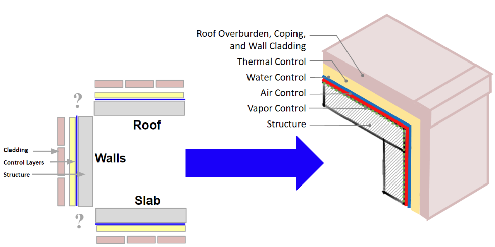
The “ideal” roof to wall example, demonstrating perfect corner connections that are true for all sides of the building. If only it were this simple!
Confronting the Enclosure Puzzle
How is a building enclosure defined? A building is not simply walls and a roof; in reality it is a cube with six sides: the roof, fenestration, above grade walls, below grade walls, and floor systems. More than that—these pieces are all connected. Each side must be connected and transitioned, and this interconnection means considering the impact that different sides and conditioned spaces have on each other.
Building science is, in essence, the study of the impacts of heat, air, and moisture on the building enclosure. Through the study of building science, the design professional can learn how to better control and prevent damage from air and moisture infiltration, and how to improve the overall energy efficiency, durability, and long-term performance of buildings. Rather than viewing the elements of a building as a collection of individual and unrelated components, ensuring performance of the building enclosure requires a systems perspective. Avoiding risks in a building structure requires understanding how the increasingly complex systems required in a building come together, stay together, and perform together, throughout the life of the structure.
The answer professionals are looking for in designing an enclosure is how to get results out of the building. How are expectations achieved? Unfortunately, a building enclosure is not a simple catalog order, it is a compilation of many, many things. Creating a successful building enclosure means confronting the challenge of combining interconnected materials, assemblies, sealed joints, and components. Once selected, these elements must all be correctly assembled, in either the factory or field, and sequenced appropriately.
Casting A Vision: The Ideal Wall
The ideal, or “perfect,” wall is an environmental separator. Its job? Simply stated, the ideal wall has to keep the outside out, and the inside in, writes Joseph Lstiburek, Principal Ph.D., P.Eng., ASHRAE Fellow, at Building Science Corporation. “In order to do this the wall assembly has to control rain, air, vapor, and heat. The best place for the control layers is to locate them on the outside of the structure in order to protect the structure. And since most of the bad stuff comes from outside the best place to control the bad stuff is on the outside of the structure before it gets to the structure.”
The Role of Control Layers
The world, in practice, is not an ideal place. How can the architect and construction team make an ideal wall in an unideal world? It falls to the design professional to determine what is included, how it is verified, and what the performance goal is. Control layer is the term used for the parts of the building enclosure that are designed to stop external elements from moving uncontrolled through a structure. There are four main control layers in a building: they address liquid water, air, heat, and water vapor. Whether the control layer completely stops the movement of the elements or slows down the movement depends on the materials used and the needs of the building.
All of the control layers need to work together to achieve maximum effectiveness. The first step of design is ensuring that control layers are continuous. Any breaks, or discontinuities, in the system can lead to trouble. While flat parts of the building enclosure can be designed relatively easily with a line for each control layer, managing the control layers becomes increasingly complicated at foundation, wall, and roof systems interfaces and as details, like parapets and penetrations, are added.
Is there a right and wrong order for control layers? As Lstiburek points out, “If you can’t keep the rain out, don’t waste your time on the air. If you can’t keep the air out, don’t waste your time on the vapor.” The order of priority begins with controlling for water.
Controlling Water
Preventing bulk water from infiltrating the building enclosure at any point is of first concern when managing moisture. Water control strategies should be planned following the path that water flows: starting at the top and traveling down to the bottom of the structure. The phrase “Slope to drain and then drip” offers a good strategy summary for the roof; walls should allow for continuation of the drainage pathway. The water control layer should be continuous across all six sides of the building enclosure. The primary water control layer is the exterior surface of the structure, with a secondary water resistive barrier further into the assembly creating a final stopping point for intrusion. Challenges in management always occur at interfaces, but it is important to note that moisture intrusion cannot be completely avoided, it must instead be managed. A durable enclosure should manage incidental water with minimal longterm impacts through diffusion, venting, and drainage strategies. First, the building should be designed to drain, or take bulk water away, from the assembly. This involves designing elements such as drainage pathways, weeps, and establishing through-wall flashings. Second, moisture management success relies on venting. Venting prevents air intrusion into assemblies and provides a ventilation path to the exterior, beyond the thermal envelope. Lastly, moisture management utilizes diffusion, which allows drying of the assembly through diffusion in at least one direction. Is there a place for any water to go so it dries versus collects.
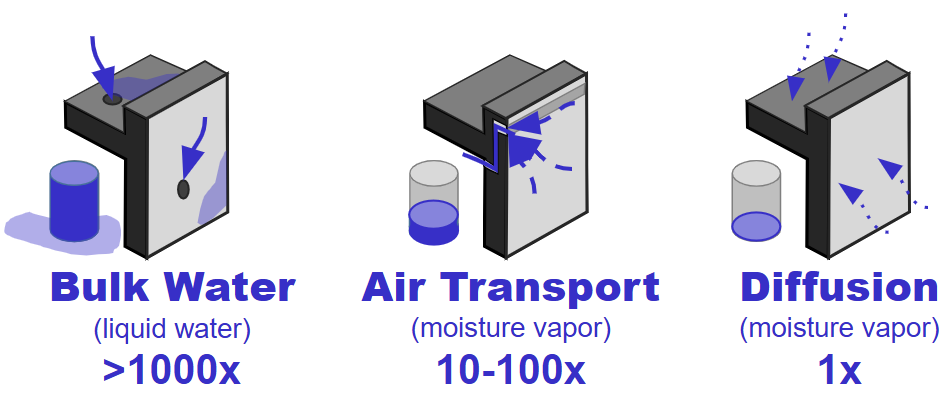
Figure courtesy of Siplast
Relative moisture risks associated with different forms of moisture. Bulk water clearly presents the largest moisture threat and must be dealt with as a first priority
Performance testing for water control layers is assessed at the material, assembly, and in situ level. Materials can be assessed through AATCC 127, AC28, or AC212 testing. These results indicate a material’s resistance to moisture. These tests are most applicable for materials that will be below grade or facing constant water.
Assemblies are assessed for moisture management via ASTM E331, AC28, or AC212. In situ testing is performed following ASTM E1105, AAMA 501.1 or AAMA 501.2. Not only does in situ testing check the interface between assembly components, it also assesses the level of detailing and craftsmanship in the installation.
Controlling Air
Controlling for air increases design complexity. The goal of an air control layer is the prevention of uncontrolled air movement. There are three main types of air movement through a building enclosure assembly: infiltration, exfiltration, and intrusion.
The most common forms of uncontrolled air leakage are infiltration and exfiltration, where outside air travels into or out of the building, respectively. Infiltration and exfiltration are what is measured through air leakage testing. The IECC sets limits on these measurements when whole building airtightness testing is required. Air intrusion occurs when air within the building travels from conditioned space into unconditioned areas within the building enclosure, such as into the roof assembly or floor line space. It moves through the space, and then back into the conditioned part of the building. While this movement is not classified by the building or energy code as air leakage, it can still cause issues due to the heat and moisture that it brings into areas of the building that may not be designed to manage it. For example, in a cold climate, interior air that travels into the roof assembly can cool and create the potential for condensation. Condensation on the roof deck can lead to mold and decay.
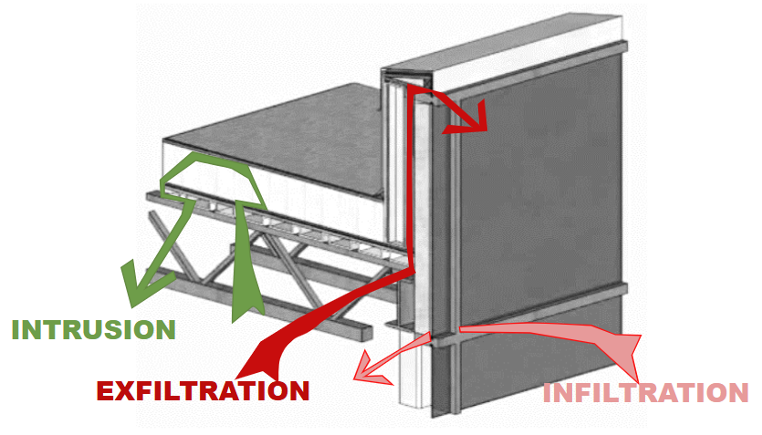
Figure courtesy of Siplast
Types of air movement present in the building enclosure.
To prevent the uncontrolled movement of air through the building enclosure, the air barrier must be made of systems and assemblies—a combination of materials working together—to prevent air leakage. The air control layer should be continuous across roofs and walls and must have continuity at interfaces. Per Section C103.2.1 of the IECC, it is the designer of record’s responsibility to detail the continuous air barrier around the entire building enclosure.
To qualify materials as an air barrier, for the material only the applicable test follows ASTM 2178. Assemblies are tested via ASTM E2357, ASTM E1677, ASTM E1680, or ASTME283. Whole building air barrier testing should adhere to ASTM E779, ASTM E1827, or ASTM E3158. Whole building testing is becoming more popular and is increasingly mandated to receive a Certificate of Occupancy (COD). Washington State, Maryland, IIECC 2021+, 90.1 2019+ all require this test.
Insulation and Thermal Control
The thermal control layer is designed to resist the movement of heat from one side of the building enclosure to the other. Proper thermal control means continuity of insulation, allowing the envelope to perform as expected and prevent condensation. Continuous insulation is explicit in the code, within IECC as well as ASHRAE 90.1. The thermal control layer follows the same principles as the other control layers. IECC C103.2 outlines thermal envelope requirements, and thermal bridging requirements are covered in IECC
Section C402
Any breaks in the thermal control layer or insufficient insulation will increase the risk of condensation occurring at that location, whether it be from humidity in the conditioned space or uncontrolled water vapor entering the assembly from elsewhere. Logistics for planning and installation can be challenging when faced with unique details. Solutions for details like parapets will depend on construction type, location of insulation in the wall and roof assemblies, and design preference for the boundary of the conditioned space.
Figure courtesy of Siplast
The “ideal” roof to wall example, demonstrating perfect corner connections that are true for all sides of the building. If only it were this simple!
Confronting the Enclosure Puzzle
How is a building enclosure defined? A building is not simply walls and a roof; in reality it is a cube with six sides: the roof, fenestration, above grade walls, below grade walls, and floor systems. More than that—these pieces are all connected. Each side must be connected and transitioned, and this interconnection means considering the impact that different sides and conditioned spaces have on each other.
Building science is, in essence, the study of the impacts of heat, air, and moisture on the building enclosure. Through the study of building science, the design professional can learn how to better control and prevent damage from air and moisture infiltration, and how to improve the overall energy efficiency, durability, and long-term performance of buildings. Rather than viewing the elements of a building as a collection of individual and unrelated components, ensuring performance of the building enclosure requires a systems perspective. Avoiding risks in a building structure requires understanding how the increasingly complex systems required in a building come together, stay together, and perform together, throughout the life of the structure.
The answer professionals are looking for in designing an enclosure is how to get results out of the building. How are expectations achieved? Unfortunately, a building enclosure is not a simple catalog order, it is a compilation of many, many things. Creating a successful building enclosure means confronting the challenge of combining interconnected materials, assemblies, sealed joints, and components. Once selected, these elements must all be correctly assembled, in either the factory or field, and sequenced appropriately.
Casting A Vision: The Ideal Wall
The ideal, or “perfect,” wall is an environmental separator. Its job? Simply stated, the ideal wall has to keep the outside out, and the inside in, writes Joseph Lstiburek, Principal Ph.D., P.Eng., ASHRAE Fellow, at Building Science Corporation. “In order to do this the wall assembly has to control rain, air, vapor, and heat. The best place for the control layers is to locate them on the outside of the structure in order to protect the structure. And since most of the bad stuff comes from outside the best place to control the bad stuff is on the outside of the structure before it gets to the structure.”
The Role of Control Layers
The world, in practice, is not an ideal place. How can the architect and construction team make an ideal wall in an unideal world? It falls to the design professional to determine what is included, how it is verified, and what the performance goal is. Control layer is the term used for the parts of the building enclosure that are designed to stop external elements from moving uncontrolled through a structure. There are four main control layers in a building: they address liquid water, air, heat, and water vapor. Whether the control layer completely stops the movement of the elements or slows down the movement depends on the materials used and the needs of the building.
All of the control layers need to work together to achieve maximum effectiveness. The first step of design is ensuring that control layers are continuous. Any breaks, or discontinuities, in the system can lead to trouble. While flat parts of the building enclosure can be designed relatively easily with a line for each control layer, managing the control layers becomes increasingly complicated at foundation, wall, and roof systems interfaces and as details, like parapets and penetrations, are added.
Is there a right and wrong order for control layers? As Lstiburek points out, “If you can’t keep the rain out, don’t waste your time on the air. If you can’t keep the air out, don’t waste your time on the vapor.” The order of priority begins with controlling for water.
Controlling Water
Preventing bulk water from infiltrating the building enclosure at any point is of first concern when managing moisture. Water control strategies should be planned following the path that water flows: starting at the top and traveling down to the bottom of the structure. The phrase “Slope to drain and then drip” offers a good strategy summary for the roof; walls should allow for continuation of the drainage pathway. The water control layer should be continuous across all six sides of the building enclosure. The primary water control layer is the exterior surface of the structure, with a secondary water resistive barrier further into the assembly creating a final stopping point for intrusion. Challenges in management always occur at interfaces, but it is important to note that moisture intrusion cannot be completely avoided, it must instead be managed. A durable enclosure should manage incidental water with minimal longterm impacts through diffusion, venting, and drainage strategies. First, the building should be designed to drain, or take bulk water away, from the assembly. This involves designing elements such as drainage pathways, weeps, and establishing through-wall flashings. Second, moisture management success relies on venting. Venting prevents air intrusion into assemblies and provides a ventilation path to the exterior, beyond the thermal envelope. Lastly, moisture management utilizes diffusion, which allows drying of the assembly through diffusion in at least one direction. Is there a place for any water to go so it dries versus collects.
Figure courtesy of Siplast
Relative moisture risks associated with different forms of moisture. Bulk water clearly presents the largest moisture threat and must be dealt with as a first priority
Performance testing for water control layers is assessed at the material, assembly, and in situ level. Materials can be assessed through AATCC 127, AC28, or AC212 testing. These results indicate a material’s resistance to moisture. These tests are most applicable for materials that will be below grade or facing constant water.
Assemblies are assessed for moisture management via ASTM E331, AC28, or AC212. In situ testing is performed following ASTM E1105, AAMA 501.1 or AAMA 501.2. Not only does in situ testing check the interface between assembly components, it also assesses the level of detailing and craftsmanship in the installation.
Controlling Air
Controlling for air increases design complexity. The goal of an air control layer is the prevention of uncontrolled air movement. There are three main types of air movement through a building enclosure assembly: infiltration, exfiltration, and intrusion.
The most common forms of uncontrolled air leakage are infiltration and exfiltration, where outside air travels into or out of the building, respectively. Infiltration and exfiltration are what is measured through air leakage testing. The IECC sets limits on these measurements when whole building airtightness testing is required. Air intrusion occurs when air within the building travels from conditioned space into unconditioned areas within the building enclosure, such as into the roof assembly or floor line space. It moves through the space, and then back into the conditioned part of the building. While this movement is not classified by the building or energy code as air leakage, it can still cause issues due to the heat and moisture that it brings into areas of the building that may not be designed to manage it. For example, in a cold climate, interior air that travels into the roof assembly can cool and create the potential for condensation. Condensation on the roof deck can lead to mold and decay.
Figure courtesy of Siplast
Types of air movement present in the building enclosure.
To prevent the uncontrolled movement of air through the building enclosure, the air barrier must be made of systems and assemblies—a combination of materials working together—to prevent air leakage. The air control layer should be continuous across roofs and walls and must have continuity at interfaces. Per Section C103.2.1 of the IECC, it is the designer of record’s responsibility to detail the continuous air barrier around the entire building enclosure.
To qualify materials as an air barrier, for the material only the applicable test follows ASTM 2178. Assemblies are tested via ASTM E2357, ASTM E1677, ASTM E1680, or ASTME283. Whole building air barrier testing should adhere to ASTM E779, ASTM E1827, or ASTM E3158. Whole building testing is becoming more popular and is increasingly mandated to receive a Certificate of Occupancy (COD). Washington State, Maryland, IIECC 2021+, 90.1 2019+ all require this test.
Insulation and Thermal Control
The thermal control layer is designed to resist the movement of heat from one side of the building enclosure to the other. Proper thermal control means continuity of insulation, allowing the envelope to perform as expected and prevent condensation. Continuous insulation is explicit in the code, within IECC as well as ASHRAE 90.1. The thermal control layer follows the same principles as the other control layers. IECC C103.2 outlines thermal envelope requirements, and thermal bridging requirements are covered in IECC
Section C402
Any breaks in the thermal control layer or insufficient insulation will increase the risk of condensation occurring at that location, whether it be from humidity in the conditioned space or uncontrolled water vapor entering the assembly from elsewhere. Logistics for planning and installation can be challenging when faced with unique details. Solutions for details like parapets will depend on construction type, location of insulation in the wall and roof assemblies, and design preference for the boundary of the conditioned space.
Vapor Control
The vapor control layer is responsible for slowing the movement of moisture vapor through the building enclosure. Unlike impacts from thermal, water, or air discontinuities, vapor diffusion is a slow process. Understanding the vapor control layer can be extremely challenging.
As defined by the IBC, moisture vapor will stop moving at a material with a permeance of <0.01 perms when tested to ASTM E96. As such, a separate vapor retarder or vapor barrier may not be required and may actually cause damage to the structure if used improperly.
To avoid unintended consequences, the designer should first be aware of the vapor permeance of all the layers in the enclosure and verify the location of any low permeance vapor retarders in the assembly. Many materials may already limit vapor. If there is more than one low permeance vapor retarder in the assembly, moisture can get trapped between layers, leading to condensation and related issues. The decision matrix for where a vapor retarder is located within the assembly comes down to building use, climate zone, the design of the enclosure, and outside humidity levels that need to be considered.
Investigating Critical Wall Transitions: Practical Applications
As demonstrated in Casey O. Study Junior High, identifying and maintaining continuity of the four key control layers is important in the design phase. Detailing and identification of the control layers in the drawings is critical to ensuring that the design intent is implemented in the field. This can require the design and specification callouts to be very specific.
Sequencing, then, is how the designer accomplishes what was designed. If a detail is complex, proper sequencing may be the determinant of its success. This necessitates both defining the complete scope to accomplish the task and going through details, to understand how a detail is put together and verified in the field. If the sequencing of components or trades in the field impacts the intended continuity or performance of the control layer in the design, it needs to be addressed before construction starts to prevent rework.
Figure courtesy of Siplast
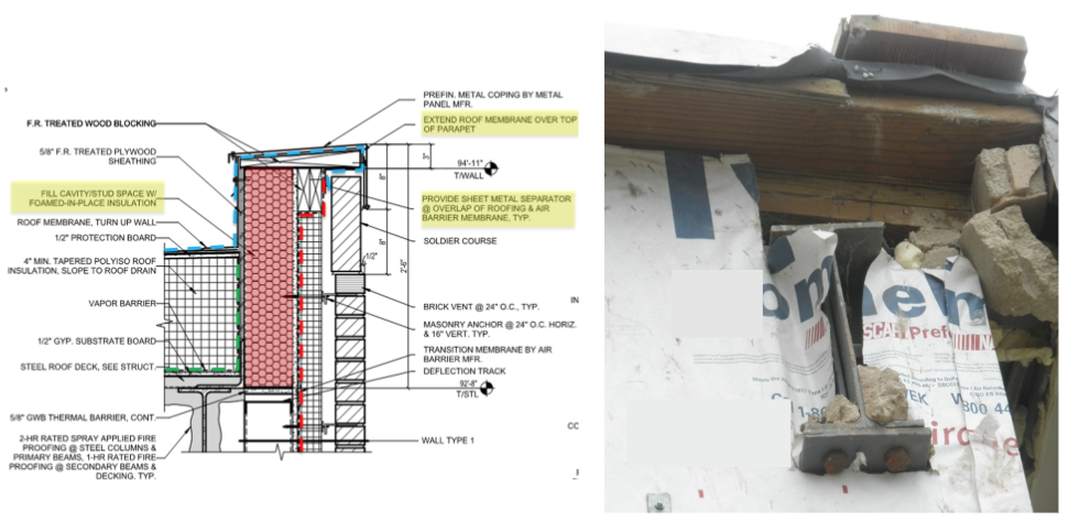
Sequencing example detailing transition that maintains continuity.
There are many approaches to handling control layers. Code requirements, budget, and building use will dictate requirements. In general, water control is managed first by the roof membrane and the cladding. A secondary water control layer, in the form of a water-resistant barrier or WRB, is often found in the wall assembly applied to the sheathing, typically behind or below the exterior insulation. Air control can be managed at the deck level of the roof, which can more readily be linked into the wall air barrier. The roof membrane can also be used as an air barrier as long as the detailing and transitions are done carefully. Thermal control continuity is maintained by connecting the roof and wall insulation, which can be challenging. This is easiest with continuous insulation on the outside of the structure. It is important to be mindful of cavity insulation or designs where insulation is split between inside the cavity and outboard of the structure, as there are potential risks for condensation due to the thermal bridges of the structure. Finally, vapor control can occur in the same plane and using the same materials as the air control layer, depending on the building’s location, construction methodologies, product choice, and use of the building.
.gif)
Figure courtesy of Siplast
Sequencing example with a parapet transition.
Code Requirements Overview
The question of how to design and sequence control layers to prevent issues in the building is not a simple one. Unfortunately, building and energy codes can further complicate the design, as the code requires both general measures and certain, specific things. IBC, IECC, NFPA, and ASCE all include various requirements for building construction that impact the enclosure directly.
The requirements for the enclosure generally come from the building code (IBC) and the energy code (IECC and ASHRAE 90.1). The requirements within the building and energy codes can be mandated prescriptively, as a performance threshold, or by reference through specific key standards. The performance standards are important because they don’t attempt to regulate by providing exhaustive lists and itemized component requirements, like a prescriptive method. These performance requirements establish the design benchmark and then provide a methodology to demonstrate compliance with the benchmark.
For example, Exterior Walls are covered in IBC Chapter 14, with weather protection, vapor retarders, and flashing all being outlined. Energy efficiency, addressed by the International Energy Conservation Code (IECC) and ASHRAE 90.1, is governed by C402 and 90.1 Chapter 5 for thermal properties, and with regards to the air barrier, by IECC C402.5 and ASHRAE 90.1 5.4.3.1. Roof assemblies are addressed in Chapter 15 of the IBC, including weather protection, requirements for roof coverings, flashing, coping, wind resistance (IBC 1504.1 and ASCE 7), and edge securement (IBC 1504.5 and SPRI ES-1). While walls and roofs are regarded as completely separate systems, to maintain continuity and controls, they are lapped and joined together.
Further requirements add further complexity, like IBC wind load considerations. Chapter 16 of the IBC establishes minimum design requirements so that the structural components of buildings are proportioned to resist loads likely to be encountered, relying on ASCE 7 to factor loads. Buildings are also assigned a risk category based on intended use. Attachment methods and roof wall interfaces are directly impacted by these requirements. There are numerous updates to ASCE 7—2005, 2010, or 2016—and each has its own nuance as to how it impacts roof design loads. Because ASCE 7 is a performance standard, it is possible to use a version with higher performance requirements because designs do not need to be the minimum allowance. For example, parapets are a combination of wall and roof pressures. The exact height of the parapet is not factored into the roof wind uplift calculations, but if the parapet is 3 feet or higher, the perimeter values can be used at the corners, lowering the uplift requirements for that portion of the roof area.
New product technology, while offering definitive performance benefits, can also alter detailing and specifications. For example, the water-resistive layer and the air-control layer are often one component. This layer is referred to as the AWB, or the air- and water-resistive barrier. There are two main types of air and water-resistive barriers: self-adhered sheets and fluid-applied membranes. Adhered systems have advantages over mechanically attached systems, and it is not uncommon to use self- adhered and fluid-applied membranes on the same project. An AWB needs to be continuous to minimize unwanted air and water movement through a building enclosure. A high-quality AWB must maintain its integrity and remain stable in high heat conditions and under UV exposure. An AWB will also need to have appropriate tensile strength, elongation capabilities, and tear resistance.
As an additional example, the decision to use vapor retarders in assemblies will determine how the different control layers are detailed at transitions and at the roof-towall interface. All vapor retarders prevent air movement, but not all air barriers stop vapor diffusion. That means that when design professionals designate the use of a vapor retarder in a roof system, that retarder is also acting as an air barrier. The caution when using the vapor retarder as the air control layer is that the vapor retarder needs to be sealed at all perimeters and penetrations in order to perform as part of the air barrier assembly. It needs to be flashed and sealed to the wall air barrier, so air does not penetrate the interface. Practically speaking, all vapor retarders are air barriers if they are installed continuously and sealed to block the passage of air.
Notably for walls, NFPA 285, which tests fire propagation of walls by assessing performance of the entire assembly, can also impact control layer material selection. Fire requirements dictate assemblies and impact air, water, and thermal control layers. Local requirements for fire blocking, assembly requirements, and assembly testing can interrupt the planned continuity of a barrier or of thermal continuity.
Ensuring Success in Reality: Key Application Properties
Architects strive to achieve a building that maximizes both design goals and performance. Ensuring performance means verifying that all functional elements, like control layers, will perform as designed. Understanding building science and creating robust control layer details and specifications helps professionals to deliver better solutions for their clients. With any project, there are many factors to consider when selecting assembly materials: their overall performance, compatibility, satisfaction of code requirements, sustainability profile, potential risks, and more. Accomplishing this complexity, or bringing design into reality, involves creating tough quality assurance along the way. Be mindful that test standards referenced are not always a guarantee of desired performance. What is an acceptable condition to for the project, not just the standard?
Steps for Success
- Specification Requirements
- Performance specs in addition to materials
- Drawings
- Detail continuous control layers
- Identify material and system transitions
- Sequenced details for complex conditions
- Account for maintenance & replacement
- Specifications
- Material and system compatibility
- Shop drawing / submittal requirements
- Define complete scope and systems
- Quality Assurance, such as mockups & testing
First, require drawing submittals that include details at the many interfaces around the building enclosure. This will confirm everyone understands how the materials are to be installed and who will install them. This will also highlight areas that may have been missed in specifications as to which trade is responsible for which part of a specific detail. Critical detail locations are often difficult to illustrate on two-dimensional drawings. They can require exploded diagrams and sequenced information to better communicate the design intent. Construction type, type of substrate, finishes, and methods of attachment the cladding vary from project to project and the control layers should be appropriate. Interior RH and usage patterns can also inform control layer material selection. Is the building used seasonally, like a school that is closed for the summer, is occupancy full-time (a residential building), or does it have daily patterns, like an office building? The reality of maintenance and service also needs to be factored in. Do the details accommodate inevitable service and repairs, while preserving the integrity of the control layer?
Next, the materials selected for each part of the system need to be vetted. Not only should the material itself be clearly specified, the performance requirements for this item should be detailed. Questions such as, “Will the materials adhere to each other, both initially and over the life of the structure?”, “Are they chemically compatible?”, and “Can they be installed in the sequence required?”, should be answered before construction starts. This information should be easily available from the selected manufacturers, along with manufacturer support to assist in any detailing questions. If substitutions are made, compatibility and adhesion of the components needs to be reconfirmed.
All materials selected will need to be assessed for compatibility and durability during exposure. How long a material will be exposed, and during what conditions, is important to evaluate. Temperature and exposure constraints during installation also need to be fully understood. A material may meet code, but it may fail to cure or perform if installed under outside weather conditions—extreme moisture or cold, for example. Additionally, the design professional should address whether meeting a test’s pass/fail criteria can achieve the intended goal, from the design perspective. Meeting a test criterion does not ensure that control layer details will survive the construction time frame or remain dimensionally stable. Additionally, the readiness of any materials to be prepped to receive flashing or further elements should be planned.
Images courtesy of Siplast
While details and sequencing can be properly drawn, these layers do not always effectively translate in the field. Communication and quality assurance between the entire construction team is crucial for creation of a successful envelope.
Quality control and assurance, through building enclosure commissioning, are a final step in protecting the integrity of the enclosure and the performance of the building. Quality control and operational maintenance are ways to ensure longterm performance of the building enclosure. It is important to have quality assurance and quality control occur throughout the project and not be confined to a final walk-through in the field. Fixing issues or missed details at the “almost done” stage is very hard when faced with sequencing realities.
Conclusion
The building enclosure is used to protect the structure and the interior from air and water intrusion resulting from rain, snow, wind, and any other climatic conditions based on season and geographic location. Its performance therefore hinges on moisture, air, vapor, and thermal control layer continuity. Drawing and designing for continuity is not optional. It is being tested. The building enclosure is a system and needs to be designed to perform as one. Given the exceptional complexity of code requirements and material interactions across the system interface, it is critical to provide details, drawings, and specific examples so that the construction team is on the same page. Specifications should never be viewed as suggestions. They should be seen as a requirement. The goal of managing enclosure durability is to establish performance expectations, allow enclosures to perform as intended, continue to perform through the project lifecycle, and be serviced or maintained in a way that minimizes risk of damage to the enclosure and performance of other critical building systems.
This article contains information created by a variety of sources, including internal and third-party writers. The opinions and views expressed do not necessarily represent those of Siplast. The content is for informational purposes only. It is not intended to constitute financial, accounting, tax, or legal advice, or professional design advice as to any particular project. In no event shall Siplast be held responsible or liable for errors or omissions in the content or for the results, damages or losses caused by or in connection with the use of or reliance on the content.
References:
- Lstiburek, Joseph. “BSI-001: The Perfect Wall.” Building Science.com Corporation. July 15, 2010. https:// buildingscience.com/documents/insights/bsi-001-theperfect-wall. Accessed April 5, 2025.
- Ibid.
- Meyer, Benjamin. “Parapets Part 2: Navigating Codes.” Building Science. GAF Roof Views Blog. January 24, 2020. https://www.gaf.com/en-us/blog/building-science/parapetspart-2-navigating-codes-281474980028067. Accessed April 8, 2025.
- Ibid.
- Kirby, Jim AIA. “Air and Water-Resistive Barriers.” Siplast. March 2024. https://documents.siplast.com/Brochure%20 and%20Bulletin/siplast_building_enclosure_air_water_ resistive_barriers_white_paper.pdf. Accessed April 8, 2025.
- Ibid.
- Meyer, Benjamin. “Designing for Moisture Durability & Energy Efficiency.” Building Science. GAF Roof Views Blog. May 6, 2020. https://www.gaf.com/en-us/blog/ building-science/designing-for-moisture-durability--energyefficiency-281474980028035. Accessed April 8, 2020.
Benjamin Meyer is the Building Enclosure Business Director with Siplast. Previous experience includes: enclosure consultant principal, technical management for enclosure products, architecture, real-estate development and construction management. Serves as a past Member of the LEED Technical Committee, Chair of the ASHRAE 90.1 Envelope Committee, and a Director of ABAA.
Herman Lopez is the Building Enclosure Business Development Manager with Siplast. He is based in Fort Collins, CO. Herman and his team are responsible for specification development and demand creation throughout the U.S. Herman has over 25 years of sales and business development experience, is active with the CSI (Construction Specifications Institute) and the BEC (Building Enclosure Council), and speaks at many AlA-BEC Chapter meetings throughout the US.
.gif)