This CE Center article is no longer eligible for receiving credits.
Controlling air leakage is an important factor in maintaining
a building's energy efficiency. According to the United
States Department of Energy, some 40 percent of the energy
of heating and cooling a building is lost by uncontrolled
air leakage through the building enclosure. As a result, North
American energy codes have started to address airtight qualities
in buildings. Uncontrolled air leakage could have consequences
beyond increased energy consumption, regarding health and
safety of the building occupants, as well as premature deterioration
of building materials.
This article will focus on air barrier membranes, which are
materials specifically designed to control airflow. Lightweight,
yet strong, air barrier membranes can control unwanted air
leakage and create an airtight building, while enhancing the
comfort of interior environments, building envelope durability,
and energy efficiency in a way that's cost effective
and visually unobtrusive. And the payoff in energy savings
can be significant. A 2005 National Institute of Standards
and Technology (NIST) study indicates that an air barrier
system could reduce air leakage by up to 85 percent, and realize
a 40 percent savings in natural gas, and a 25 percent savings
in electricity.
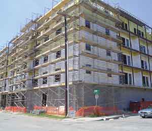
The Metropolitan
Club at Hotel ZaZa.
It is located at 2403 Thomas Ave., Dallas,
TX. |
|
|
The energy implications of air barriers are significant,"
says Peter J. Arsenault, AIA, NCARB, LEED-AP, principal of
Peter J. Arsenault Architect in Syracuse, New York. "Air
infiltration in a building can account for a nearly equal
degree of energy loss as insulation values. In other words,
R-values and insulation details account for about half of
the heating and cooling energy use in a building. The other
half is lost to air infiltration. Tests have shown a significant
decrease in air infiltration with proper installation of air
barriers."
Codes and Legislation Relating to Air
Barriers
Air barrier systems provide several advantages for building
projects, including increased interior comfort, durability
and energy efficiency. With these attributes, they are suitable
for a variety of applications in various climates.
Air barriers have the potential to reduce air leakage to
acceptable levels for less than $1.50/square foot of gross
building area, and are often specified for buildings. Air
barriers are typically regulated through energy codes, which
recognize the importance of airtight buildings and energy
efficiency. As of early 2006, several states have developed
existing and pending legislation on air barriers, as well
as compliance criteria.
|
Summary of Existing and Proposed
Energy Codes
|
|
Codes & Regulations
|
Compliance Requirements
Air Infiltration, cfm/ft2 @ 0.30 in water (75Pa)
|
|
Material
ASTM E2178
|
Assembly
ASTM E1677
|
Whole Bldg.
ASTM E799
|
| The
National Building Code of Canada (1995 NBC) |
0.004
|
--
|
--
|
| Massachusetts
Energy Code (July 2001) |
0.004
|
--
|
--
|
| WI
Energy Code |
--
|
0.06
|
--
|
| MN
Energy Code (Proposal) |
0.004
|
|
--
|
| ASHRAE
90.1* (Proposal approved 2005) |
0.004
|
0.04
|
0.4
|
| *
ASHRAE proposal has 3 compliance options: Material,
Assembly, or Whole Building. Summary of existing
and proposed energy codes |
|
The 1995 National Building Code of Canada (NBC code) requires
a continuous air barrier for all commercial buildings. Massachusetts
was the first state to adopt an energy code, in 2001, which
is similar to the NBC code, and requires a continuous air
barrier for commercial buildings. Wisconsin adopted an energy
code in 2003. Minnesota is developing an energy code in early
2006, with similar compliance criteria as the Massachusetts
energy code. In addition, as of 2003, the Envelope Design
Guidelines for Federal Office Buildings and Multi-Family High
Rise Residential Buildings require air barriers.
As air barriers are better understood and the benefits are
documented, more jurisdictions will likely be following suit.
In 2005, the American Society of Heating, Refrigeration and
Air-Conditioning Engineers (ASHRAE) approved an amendment
to the ASHRAE 90.1 model energy code that would require an
air barrier for most commercial buildings in most climate
zones. With their clear advantages and the imminent code requirements,
it's critical that architects understand the air barrier
functions and benefits, and how to specify them.
The Physics of Air And Moisture Transport
Through The Building Enclosure
To gain a proper working understanding of the role of air
barriers in building enclosures, some basic terminology and
fundamental physics must first be defined. The building enclosure,
also known as the building envelope, refers to the part of
the building that physically separates the interior conditioned
space from the exterior environment. Its main function is
to control all loadings due to separation of the two environments,
the flow of mass and flow of energy. Air barriers are an important
component of the building enclosure.
Air Leakage
Air leakage through the building enclosure refers to the
unplanned, unpredictable, and unintentional airflow in or
out of buildings, and must be distinguished from the intentional
and, ideally, controlled flow of outdoor air into a building
via either a mechanical or a ventilation system. A building
can be very tight in terms of air leakage and have sufficient
ventilation; conversely, a building could be very leaky and
have insufficient ventilation. In mechanically ventilated
buildings, it is desirable to have an airtight building enclosure,
which is achieved by connecting materials with high air infiltration
resistance into a continuous air barrier system.
In order for air leakage to occur, there must be a driving
force and a pathway.The driving
force for air leakage is the difference in total air
pressure across the building enclosure, with airflow occurring
from higher to lower pressure, or from positive to negative
pressure. There are three main sources of air pressure difference.
The wind pressure
is a significant factor and it is usually high (positive)
on the windward side, and low (negative) on the leeward side
of the building. When averaged over the course of a year,
industry experts estimate that wind pressure is about 10 to
15 miles per hour (0.2 to 0.3 pounds per square foot) in most
locations in North America.
Stack pressure (also
called chimney effect or buoyancy) is caused by the atmospheric
pressure difference between the top and bottom of a building,
which is in turn caused by the temperature difference and
hence the difference in the weight of the columns of indoor
and outdoor air. In cold climates, during winter, the stack
effect can cause infiltration of cold air at the bottom and
exfiltration of warmer air at the top of the building. The
reverse occurs in summer, with air conditioning.
Mechanical pressure
is caused by heating, ventilation and air conditioning (HVAC)
system pressurization. HVAC engineers tend to design buildings
with slight positive pressures in order to reduce infiltration
and associated pollution. However, this practice might not
be ideal in some climates, such as in cold climates.
|
Main Sources of Air Pressure
Differentials in Buildings
|
|
|
|
The main types ofairflow
pathways include diffuse flow and concentrated pathways.
Diffuse flow occurs through leaky materials and assemblies,
such as fibrous insulation, uncoated masonry (such as concrete
masonry units and brick), or other porous building materials.
Concentrated flow occurs through unintended openings. Direct
channel flow or orifice flow, which occurs when the air enters
and exits in a direct path, has the highest cost penalty because
of high energy loss. Offset channel leaks are the most damaging
because of longer pathways, which allow for air to change
its temperature and to reach the dew point within the building
enclosure leading to interstitial condensation. Flow leaks
occur between floors and could add to stack effect.
Moisture Transport
Moisture moves through the building enclosure as liquid water
or as water vapors. The difference between the two physical
states of water is the size of the molecular aggregates: liquid
water exists as large molecular aggregates (up to 100 molecules
at room temperature), while water vapors exist as free molecules.
Consequently, the transport mechanisms are different for liquid
water and water vapors.
Liquid water
The main source of liquid water for above grade walls is
rain, which can infiltrate behind the exterior cladding and
be driven into the building enclosure by four main forces:
Gravity can draw water
down through openings and cracks, and into the construction
assembly.
Capillary forces act
like a sponge sucking water through small cracks and pores.
Smaller cracks result in greater capillary forces.
Rain droplets can
pass through openings in the exterior cladding, driven by
the momentum of falling rain drops.
Thepressure differential
can push or suck water through openings and cracks, into the
construction assembly.
There are three basic types of exterior wall design, from
the standpoint of rain penetration control.
- Face-sealed (barrier)
walls rely upon every seam and crack to be face sealed.
This design requires detailed workmanship and continuous
maintenance, and is most vulnerable to rain infiltration.
This design is effective only in areas with low wind and
rain exposure. Examples of barrier walls include non-drainage
Exterior Insulation Finish Systems (EIFS) and face-sealed
curtain walls.
- Concealed barrier walls
rely on multiple layers for rain penetration control. In
contrast to face-sealed systems, these walls include a drainage
plane within the wall assembly that functions as a second
line of defense against water intrusion. The drainage plane
is usually a water resistive barrier membrane. This design
is effective in areas with moderate wind and rain exposure.
A typical example of a concealed barrier wall is the drainage
stucco system.
- Drained cavity or rain
screen walls rely on two layers and a drained cavity
space for rain penetration control. This design is similar
to the concealed barrier system in that it provides two
lines of defense, but it offers additional features, such
as capillary breaks between porous materials, freer drainage,
and venting or ventilation to limit average relative humidity
(RH)) outside of sheathing. This design is most effective
in rain penetration control and should be used in areas
with high wind and rain exposure. Examples of rain screen
walls include brick-veneer cavity walls, furred-out clapboard
walls, and drainable EIFS walls.
Water vapor can be transported
through the building enclosure byair
currents and by vapor diffusion. Air currents could
carry significant amount of moisture vapors into the building
enclosure. A continuous air barrier will control airflow,
hence the moisture migration through air currents. Air-transported
moisture must not be confused with vapor diffusion.
For water vapor diffusion to occur there has to be a driving
force and a pathway. The driving force for water vapor diffusion
is the difference in water vapor concentration or difference
in vapor pressure across an assembly: water vapors flow from
an area of higher concentration (higher vapor pressure) to
an area of lower concentration (lower vapor pressure). The
ability of materials to allow vapor diffusion is measured
by vapor permeability, which is expressed in perms: the higher
the perms, the higher the vapor permeability.
The 2003 International Building Code (IBC) classifies building
materials into vapor permeable (greater than five perms) and
vapor non-permeable (less than one perm). Vapor non-permeable
materials are called vapor barriers or vapor retarders. Other
terms often used to describe vapor permeable or non-permeable
materials are"breathable"
and"non-breathable,"
respectively.
"Breathability is often associated with air flow, rather
than moisture vapor flow," notes Maria Spinu, Ph.D.,
Building Science Manager, Dupont Building Innovation. "The
use of this terminology may have contributed to the confusion
between an air barrier versus a vapor barrier function."
While the two functions could be performed by a single material,
providing an air and vapor barrier, the needs addressed are
quite different. Air barriers retard airflow, which is the
result of air pressure differences. Vapor barriers retard
water vapor flow, which is the result of water vapor concentration
differences.
Experts estimate that the amount of moisture vapor transported
by air currents can be 100 to 200 times higher than the amount
transported by vapor diffusion, and can account for more than
98 percent of all water vapor movement through the building
enclosure.
In summary, there are three main moisture sources, which
could lead to water problems in buildings: bulk water, air
transported moisture, and vapor diffusion. "The three
moisture sources do not contribute equally to the wetting
of the building enclosure," says Spinu. Liquid or bulk
water infiltration is usually the largest wetting source for
above-grade walls, followed by air transported moisture, which
is significantly higher than the amount of water vapor transported
by diffusion. It is generally accepted that the buildings
will occasionally get wet; however, moisture problems in buildings
will occur if wetting exceeds drying. Consequently, in order
to prevent moisture problems it is essential to protect the
enclosure against wetting and promote drying. Although moisture
movement by diffusion cannot be discounted as a wetting source,
it should not be the primary focus for moisture intrusion
control; vapor diffusion, however, is critical for drying.
AIR BARRIER FUNCTIONS AND BENEFITS
Uncontrolled air leakage could negatively impact building
occupant comfort, durability of building materials, and energy
consumption levels. Air barriers play a critical role in controlling
these effects of air leakage.
The primary function of an air barrier is to control air
leakage in order to avoid undesirable consequences.
|
Consequences of Air Leakage
through the
Building Enclosure
|
|
|
|
Air movement can create drafts affecting thermal comfort,
or carry contaminants and moisture through the building enclosure,
affecting indoor air quality and safety of the occupants.
Excess moisture can also condense on interior surfaces and
cause premature degradation of building materials, such as
corrosion of metal and rotting of wood. Unintentional air
leakage could lead to increased energy use in at least three
different ways: over sizing of HVAC equipment to compensate
for the heating and cooling loss through air leakage; loss
of effective R-value due to wetting of thermal insulation
by moisture transported through air currents; and loss of
effective R-value due to convective loops, also known as the
wind-washing effect.
In addition to their primary function, air barriers can protect
against water intrusion, in which case they are air and water
resistive barriers. Some air barriers also control vapor diffusion,
in which case they are air and vapor barriers. Air, water
and vapor barriers play a critical role in managing air and
moisture movement through the building enclosure. "Unfortunately,
there is still confusion on the functionality associated with
different barrier membranes, especially when a single membrane
performs multiple functions," says Spinu, noting that
the most common confusion is between air barrier and vapor
barrier functions. "While air barriers can and should
be used in all climates, vapor barriers are climate specific,"
she adds.
AIR BARRIER PERFORMANCE REQUIREMENTS
There are four main performance requirements for air barriers:
air infiltration resistance, continuity, structural integrity,
and durability.
Air infiltration resistance: An air barrier must resist airflow.
While there are no mandatory requirements at the national
level, individual states have adopted energy conservation
codes that require air tightness and allow for different compliance
options for air infiltration resistance of air barrier materials,
assemblies, or whole buildings (as previously described).
Continuity is a critical requirement for air barriers, and
depends on both design and execution. The first step is to
detail the air barrier continuity in the drawings. "A
continuous line of air tightness must be traced through every
exterior wall detail, and every connection between air barrier
components," says Spinu. The most critical connections
include: the roof and wall; wall and foundation; wall and
floors; wall and window or door interfaces; joints between
various types of exterior wall systems, and penetration details.
The design details must then be properly implemented in the
field. The air barrier system includes the primary air barrier
membranes and the installation and continuity accessories,
such as mechanical fasteners, tapes, flashing, caulks, sealants,
and primers.
Structural integrity is another attribute of an effective
air barrier. Air barriers must be able to withstand pressure
loads or be able to transfer the load to other elements of
the building envelope without rupture or displacement. For
mechanically fastened building wraps, the type of mechanical
fasteners and their spacing are important for structural integrity,
and the installation must be done according to the manufacturer's
instructions.
Finally, air barriers must be durable. They must be able
to withstand environmental exposure, including exposure to
ultraviolet (UV) rays, thermal cycles, and mechanical pressure.
These requirements extend from the construction cycle through
the service life of the enclosure. If that life-cycle requirement
can't be met, then an air barrier must be accessible
for periodic maintenance.
In addition to these basic requirements, an air barrier membrane
should also balance the critical barrier properties for optimum
moisture management: air infiltration resistance, water resistance,
and vapor permeability. The air barrier membrane should combine
high resistance to water penetration and air infiltration
(to protect against bulk water intrusion and moisture transported
by air currents, respectively), with optimum moisture vapor
permeability to allow drying from incidental moisture. The
balance of properties is generally difficult to achieve, because
the three barrier properties have competing demands. Consequently,
only few materials achieve this optimum balance, while most
excel in one or two categories.
|
Wetting vs. Drying of Building
Enclosure
|
|
|
|
The multiple consequences of uncontrolled airflow may result
in potential liability issues for the entire building community.
Architects, consultants, and engineers could be held liable
for moisture damage in buildings because of faulty design
or poor material selection. Contractors' workmanship
can be called into question when water damage is due to poor
execution of the intended design or unauthorized material
substitution. Building owners may be held responsible for
poor indoor air quality, mold problems or lack of thermal
comfort. With serious consequences for the design and building
industry professionals, building owners and building users,
it behooves all members of the building team to pay close
attention to controlling unwanted air flow and selecting the
proper barrier method.
SELECTING APPROPRIATE AIR BARRIERS
There are many types of commercial air barrier membranes.
Based on the method of application, there are three main types
of air barriers: mechanically fastened (building wraps); peel-and-stick
or self-adhered; and fluid applied. Based on vapor permeability,
air barrier materials are vapor permeable and vapor non-permeable.
Mechanically fastened membranes are vapor permeable; some
fluid applied membranes have limited vapor permeability; all
others are vapor non-permeable. While the application method
is often a personal preference, the vapor permeability of
air barrier membranes has performance implications, which
must be considered when selecting an air barrier. As a general
rule, vapor permeable air barriers can and should be used
in all climates, while vapor non-permeable air barriers (air
and vapor barriers) are climate specific.
|

|
|
|
DuPontâ„¢ Tyvek® brand protective material
is a family of tough durable sheet products of
high-density polyethylene fibers. The sheet is
formed first by spinning continuous strands of
very fine interconnected fibers, and then bonding
them together with heat and pressure.
Tyvek® is white, non-toxic, chemically inert
and contains no binders. DuPontâ„¢ Tyvek®
offers new dimensions of protection, security
and safety in a wide variety of industries including
protective apparel, construction, envelopes, medical
packaging and graphics.
In construction DuPontâ„¢ Tyvek® is used
to increase air and water resistance and provide
protection against water and moisture intrusion.
|
|
Architects note that installation is key, especially in residential
applications. The energy benefit of the house wrap is to minimize
air infiltration along sheathing joints and into framing cavities.
Literally unfolding the roll around the house in a full nine-foot
length provides a seamless wrap that then has door and window
openings cut into it. "I get frustrated by contractors
who insist on cutting up the membrane into small pieces. This
not only defeats the purpose, it creates the opportunity for
air and moisture infiltration at each seam," says Arsenault,
who has been involved in energy efficient-housing since 1980.
"Even if it is seamed properly with 18-inch overlaps
and seaming tape as the manufacturer suggests, that approach
is more costly and still prone to installation errors. This
is a sophisticated product that warrants proper installation
and attention to detail to be effective and avoid unnecessary
problems."
When selecting an air barrier it is important to understand
how it will perform in each system and under specific environmental
conditions. While the air barrier must protect against air
leakage, it should also enhance the ability of wall assemblies
to manage incidental moisture intrusion. There are two key
considerations to keep in mind when selecting an air barrier
system for a building enclosure: wall assembly design, and
climate type.
Wall Assembly Design
There are basically two types of wall assembly designs, based
on the location of thermal insulation within the wall assembly.
|
Interior vs. Exterior Insulation
|
|
|
|
The interior insulation wall design has the thermal insulation
within the wall cavity, that is, the batt insulation within
the stud cavity. In the exterior insulation design, the thermal
insulation is placed outside the wall cavity, with rigid insulation
outside of the exterior sheathing. The exterior insulation
wall, which is more commonly used in cold climates, provides
two main advantages: it eliminates the thermal bridging (which
is significant in steel stud construction) and it moves the
dew point outside the interior wall cavity, thus avoiding
condensation within the interior wall. A combination wall
design includes both batt insulation and rigid exterior insulation.
Climate type
Climate is a very important design factor when considering
air barrier selection. While the building physics principles
are universal, they must be applied to local environmental
conditions, which are climate specific. North America has
eight climate zones that could be considered as the intersection
of the three major climate types, dry, humid, and marine,
with eight thermal bands that progress northward from very
hot to very cold.
Many condensation and moisture problems may be the result
of importing building practices from one climate to another,
without considering the consequences of the local climates,
such as changes in moisture loads and vapor pressure drive.
Building practices must address climate-specific loadings
on the building enclosure. An extensive discussion on the
climate specific design is beyond the scope of this article.
However, the wall assembly design and climate type affect
the choice of air barrier.
Additional Application Methods
In addition to the three main types of air barriers previously
noted, other application methods include Sprayed Polyurethane
Foams (SPF) and torch-applied membranes. The choice of air
barriers based on the application method is often a personal
or regional preference, which takes into account the ease
of application on certain back-up walls, the material availability
and cost, the familiarity of the designer, specifier or contractor
with certain products and manufacturers, and access to certified
installers.
Vapor Permeable Versus Vapor Non-Permeable
Air Barriers
Based on vapor permeability, air barrier materials are classified
into vapor permeable and vapor non-permeable. The vapor permeability
of building materials has implications on the ability of the
building enclosure to manage the moisture loadings: vapor
permeable materials allow diffusion, while vapor non-permeable
materials do not allow diffusion. Although moisture movement
by diffusion cannot be discounted as a wetting source, diffusion
is much more critical as a drying mechanism. This is true
of all building materials. Mechanically fastened membranes
are vapor permeable; some fluid applied membranes have limited
vapor permeability; all others are vapor non-permeable. The
vapor permeability will dictate the air barrier placement
in the building assembly: vapor permeable air barriers can
be placed anywhere in the assembly, while vapor non-permeable
air barriers must generally be installed on the warm side
of the assembly, in order to avoid condensation.
Cold Climate Case Studies
To understand how the wall assembly design and climate affect
the selection of an air barrier, consider a cold climate example,
in Minneapolis, Minnesota, with a traditional cavity insulation
wall design. The air barrier for these walls is typically
installed on the exterior face of the exterior sheathing.
The next figure describes how a vapor permeable air barrier
works in this assembly for this climate.
|
Cavity insulation; Vapor permeable
Air Barrier and Interior Vapor Barrier
|
|
|
|
The exterior air barrier will protect the wall cavity against
liquid water intrusion and air infiltration, but will allow
drying from incidental moisture to the outside.
In this climate, the predominant driving force for vapor
diffusion, hence the preferred drying direction, is from the
inside to the outside. In addition, a vapor barrier on the
interior side of the wall cavity would protect against moisture
vapor diffusion from the inside. Here, the inside air is predominantly
warmer and wetter than the outside air. This cold climate
example shows that the use of an exterior vapor permeable
air barrier, in conjunction with an interior vapor barrier,
is a good practice.
A vapor non-permeable air barrier installed on the exterior
face of the exterior sheathing would perform differently with
this wall assembly, in this climate. The vapor non-permeable
air barrier combines the functions of air barrier and vapor
barrier into a single membrane. The membrane will protect
the wall cavity against liquid water intrusion and air infiltration;
however, because the membrane is vapor non-permeable (vapor
barrier), it will not allow drying from incidental moisture
to the outside, because in this climate the predominant driving
force for vapor diffusion is from the inside to the outside.
In addition, the vapor barrier would be located on the cold
side of the insulation, leading to potential condensation.
This example shows why vapor non-permeable air barriers (air
and vapor barriers) should not be used in this climate with
the interior insulation wall assembly.
|
Cavity insulation; Vapor non-permeable
Air Barrier(Air AND Vapor Barrier
|
|
|
|
Another example would be an exterior insulation wall assembly,
located in the same climate. An important characteristic for
this type of wall design is that the wall cavity is considered
part of the conditioned interior space, therefore it relies
on HVAC, and not on vapor diffusion, for removal of incidental
moisture. The air barrier in this assembly is typically sandwiched
between the rigid insulation and the exterior sheathing. Therefore,
it would be located on the warm side of the insulation. As
a result, this assembly design could use either vapor permeable
or vapor non-permeable air barrier membranes.
|
Exterior insulation wall with
air Barrier
|
|
|
|
BEST PRACTICES
The previous examples are in cold climates; however, a similar
analysis must be performed for other climates. A common mistake
is importing building practices from one climate to another,
without a fundamental understanding of building physics.
For example, vapor barriers have been introduced in Canada
to prevent interior moisture from migrating into the wall
assembly. "While this is a good practice for cold climates
where the inside air is warmer and wetter than the outside,
the use of vapor barriers in mixed or hot and humid climates
has probably contributed to moisture problems in recent years,"
says Spinu, noting that this is further aggravated by the
practice of using vinyl wall paper as an interior finish in
these climates. Such practices often lead to double vapor
barriers. "Fundamental physics must be understood in
order to avoid moisture problems. Vapor barrier use in mixed
or hot and humid climates has been challenged, and the codes
are being reviewed," Spinu adds.
The 2006 IBC code will delete section 1403.3 from the 2003
IBC version (on Vapor Retarders). The vapor retarder requirements
will be referenced to the IECC code (International Energy
Conservation Code). The major change is that vapor barriers
will no longer be required in certain constructions, for climate
zones 1, 2, 3, 4A, and 4B.
|
DOE proposed climate zones.
The climate zones 1,2,3,4A, and 4B will no longer
mandate vapor barriers (below the black line).
|
|
|
|
An extended discussion of all climate zones is beyond the
scope of this article. However, as a general rule, vapor permeable
air barriers can and should be used in all climates and all
wall designs. Vapor non-permeable air barriers, which are
air and vapor barriers, must be located on the warm side of
the thermal insulation, and their use should be climate specific.