All images courtesy of Specified Technologies
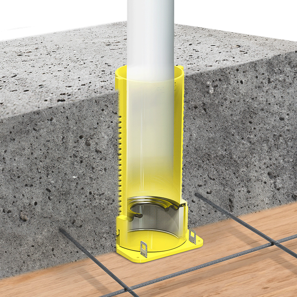
In many buildings, firestop systems are required to prevent or stop fire and smoke from moving through penetrations, joints, and the gap between fire-rated walls and curtain walls.
Firestop systems are essential to maintaining the integrity of fire-resistance-rated assemblies, yet their performance is not defined at installation alone. As third-party firestop special inspections become more common under the International Building Code (IBC), the industry is shifting from point-in-time compliance to a lifecycle approach known as continuous compliance, requiring design professionals to better understand how systems are selected, documented, and verified in the field.
This article examines firestop systems from both a technical and lifecycle perspective. Participants will explore inspection requirements, tested and listed systems, and common causes of deficiencies. The article also highlights how design and specification decisions influence long-term performance, particularly in facilities subject to ongoing inspections.
Firestop Systems and the Role of Inspection
The majority of fire-related deaths in buildings are caused by inhalation of smoke and toxic gases. Fire and smoke can easily spread through unsealed penetrations, including ducts, pipes, cables, joints, and, of course, openings such as windows and doors. For this reason, passive fire protection strategies have been developed to block these routes and “stop” fire and smoke from moving through buildings.
According to the International Firestop Council (IFC), firestopping is a process. “Firestopping is an integral part of fire protection engineering. Firestop systems protect against the passage of flames, deadly gases, and toxic smoke through openings that are created for penetrations, joints, and gaps in fire-resistive walls, floors, and floor/ceiling assemblies.” Firestop systems are used to maintain the integrity of these assemblies after they have been penetrated or otherwise modified. To be effective, fire-resistance-rated assemblies must be continuous, with all openings properly sealed.
Fire-resistance-rated assemblies support compartmentation by dividing buildings into smaller, more manageable areas. This helps limit the spread of fire and smoke to the point of origin, allowing occupants additional time to exit safely. Compartmentation also provides critical time for emergency responders to arrive and assist with evacuation, particularly for occupants who cannot egress independently. In certain occupancies, such as hospitals, assisted-living facilities, and detention centers, it also enables defend-in-place strategies where relocation may not be practical.
Firestop Systems
A firestop system is more than the firestop material or product; including the fire-rated assembly, firestop products used, how they are to be applied, and what penetrants are acceptable, as well as other relevant details. For example, a penetration firestop system includes the fire-rated assembly, whether a wall, floor, or ceiling; the penetrating item, whether a pipe, cable, or conduit; and the firestop material. Notably, the complete firestop system, not just the firestop material, is tested with achieved ratings clearly stated on the firestop system itself.
Because there are so many applications for firestop systems and so many variables involved, there are thousands of listed systems published by testing agencies such as UL, Intertek, and FM. UL has published many of these; thus, firestop systems are often informally referred to as “UL systems,” even when they are listed by another testing agency.
Firestop systems are only effective when they are installed in accordance with tested and listed assemblies and supported by clear documentation. We will come back to this concept later in this article.
Where Firestop Systems are Required
Building codes require firestop to be installed in certain locations in all commercial, industrial, and multi-family buildings.
All penetrations, which include any opening that passes entirely through a fire-rated wall or floor, must be firestopped. Examples of penetrations include sprinkler pipes or non-dampered HVAC ducts. Blank openings, often places where pipes or cables have been moved, must also be treated.
Firestop is also required at membrane penetrations, which are penetrations that breach only one side of a fire-rated assembly without passing completely through. Examples include openings where an electrical box or datacom outlets are installed.
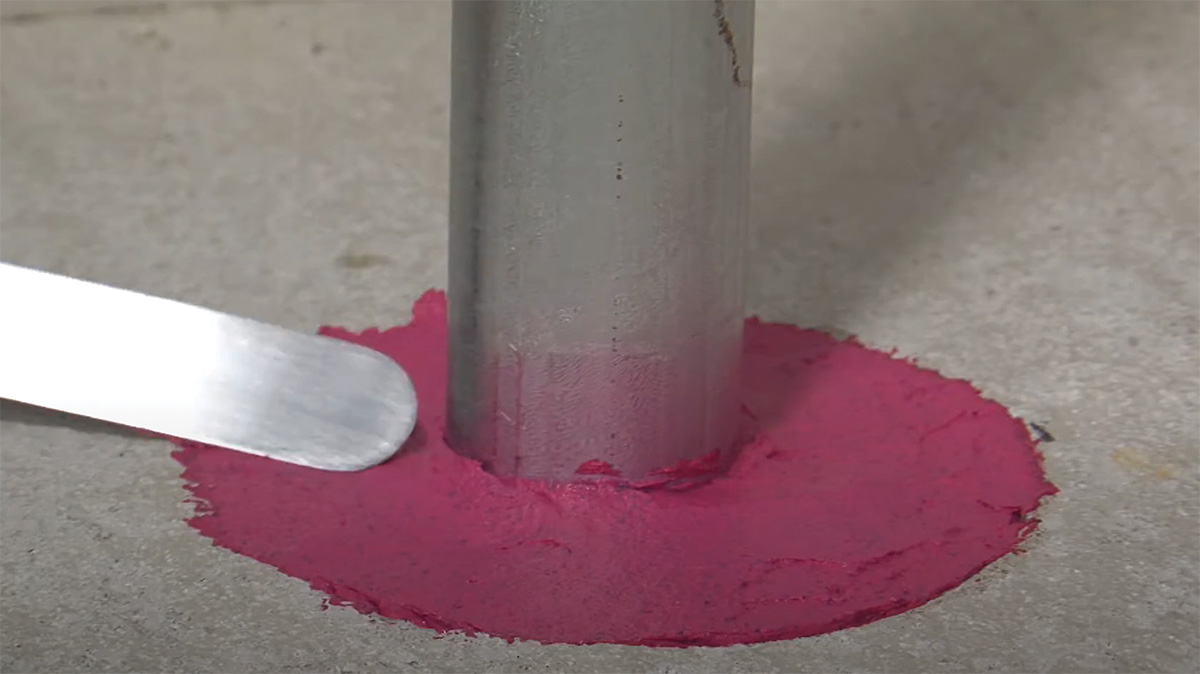
Here, firestop sealant is being applied to a penetration. The firestop product is just one part of a firestop system.
Joints represent another large category where a firestop is required. These typically linear openings, where two assemblies meet, include construction joints between the top of a fire-rated wall and the rated floor/ceiling assembly above; between the bottom of a fire-rated wall and the top surface of the floor assembly that the wall is built upon; and between rated walls.
Another critical area that requires firestopping is where the edge of a fire-rated floor assembly meets the exterior wall of a building. Perimeter Fire Containment (PFC) conditions, sometimes referred to as “edge of slab,” are critical to prevent flame spread vertically by restricting flame propagation from a lower floor to an upper floor. Notably, while most floors have a 1 – or 2-hour fire rating, curtain walls are often non-rated. This is why joint conditions incorporating Curtain Walls are tested to a different standard than interior construction joints.
Architects are responsible for specifying firestop systems, but the responsibility does not stop there. It is vital that firestop systems are not only correctly specified, but also properly installed and verified. In addition, code also requires special inspections for firestop systems in some buildings. As these third-party firestop inspections become more common, building professionals should understand what inspectors are looking for and how to prepare for these inspections. Not only will this help avoid costly repairs, but it will also ensure the long-term performance of passive fire protection systems.
Codes, Standards, and Inspection Requirements
All model codes, including the International Building Code (IBC), NFPA 101 Life Safety Code, and NFPA 70 National Electrical Code, require firestopping. The IBC also references other codes, such as the International Plumbing Code, International Mechanical Code, and National Electrical Code, all of which include provisions requiring firestopping where systems penetrate rated assemblies. Over time, the requirements have been refined and clarified. Key references for firestop in IBC (2021 version) include:
- Penetrations in fire-resistance-rated walls (Section 714.4)
- Penetrations in fire-resistance-rated floors, floor/ceiling assemblies, or the ceiling membranes of a roof/ceiling assembly (Section 714.5)
- Fire-resistant joint systems (Section 715.1)
- Exterior curtain wall and fire-resistance floor intersection (Section 715.4)
These requirements form the foundation for state and local codes, although jurisdictions vary in how they adopt the IBC. Some adopt it as it is written, while others add amendments tailored to local conditions and practices; thus, it is always important to check to learn which codes apply. In any case, firestop remains a core component of the architect’s responsibilities under Division 07, supporting code compliance, occupant safety, and building performance.
All images courtesy of Specified Technologies
In many buildings, firestop systems are required to prevent or stop fire and smoke from moving through penetrations, joints, and the gap between fire-rated walls and curtain walls.
Firestop systems are essential to maintaining the integrity of fire-resistance-rated assemblies, yet their performance is not defined at installation alone. As third-party firestop special inspections become more common under the International Building Code (IBC), the industry is shifting from point-in-time compliance to a lifecycle approach known as continuous compliance, requiring design professionals to better understand how systems are selected, documented, and verified in the field.
This article examines firestop systems from both a technical and lifecycle perspective. Participants will explore inspection requirements, tested and listed systems, and common causes of deficiencies. The article also highlights how design and specification decisions influence long-term performance, particularly in facilities subject to ongoing inspections.
Firestop Systems and the Role of Inspection
The majority of fire-related deaths in buildings are caused by inhalation of smoke and toxic gases. Fire and smoke can easily spread through unsealed penetrations, including ducts, pipes, cables, joints, and, of course, openings such as windows and doors. For this reason, passive fire protection strategies have been developed to block these routes and “stop” fire and smoke from moving through buildings.
According to the International Firestop Council (IFC), firestopping is a process. “Firestopping is an integral part of fire protection engineering. Firestop systems protect against the passage of flames, deadly gases, and toxic smoke through openings that are created for penetrations, joints, and gaps in fire-resistive walls, floors, and floor/ceiling assemblies.” Firestop systems are used to maintain the integrity of these assemblies after they have been penetrated or otherwise modified. To be effective, fire-resistance-rated assemblies must be continuous, with all openings properly sealed.
Fire-resistance-rated assemblies support compartmentation by dividing buildings into smaller, more manageable areas. This helps limit the spread of fire and smoke to the point of origin, allowing occupants additional time to exit safely. Compartmentation also provides critical time for emergency responders to arrive and assist with evacuation, particularly for occupants who cannot egress independently. In certain occupancies, such as hospitals, assisted-living facilities, and detention centers, it also enables defend-in-place strategies where relocation may not be practical.
Firestop Systems
A firestop system is more than the firestop material or product; including the fire-rated assembly, firestop products used, how they are to be applied, and what penetrants are acceptable, as well as other relevant details. For example, a penetration firestop system includes the fire-rated assembly, whether a wall, floor, or ceiling; the penetrating item, whether a pipe, cable, or conduit; and the firestop material. Notably, the complete firestop system, not just the firestop material, is tested with achieved ratings clearly stated on the firestop system itself.
Because there are so many applications for firestop systems and so many variables involved, there are thousands of listed systems published by testing agencies such as UL, Intertek, and FM. UL has published many of these; thus, firestop systems are often informally referred to as “UL systems,” even when they are listed by another testing agency.
Firestop systems are only effective when they are installed in accordance with tested and listed assemblies and supported by clear documentation. We will come back to this concept later in this article.
Where Firestop Systems are Required
Building codes require firestop to be installed in certain locations in all commercial, industrial, and multi-family buildings.
All penetrations, which include any opening that passes entirely through a fire-rated wall or floor, must be firestopped. Examples of penetrations include sprinkler pipes or non-dampered HVAC ducts. Blank openings, often places where pipes or cables have been moved, must also be treated.
Firestop is also required at membrane penetrations, which are penetrations that breach only one side of a fire-rated assembly without passing completely through. Examples include openings where an electrical box or datacom outlets are installed.
Here, firestop sealant is being applied to a penetration. The firestop product is just one part of a firestop system.
Joints represent another large category where a firestop is required. These typically linear openings, where two assemblies meet, include construction joints between the top of a fire-rated wall and the rated floor/ceiling assembly above; between the bottom of a fire-rated wall and the top surface of the floor assembly that the wall is built upon; and between rated walls.
Another critical area that requires firestopping is where the edge of a fire-rated floor assembly meets the exterior wall of a building. Perimeter Fire Containment (PFC) conditions, sometimes referred to as “edge of slab,” are critical to prevent flame spread vertically by restricting flame propagation from a lower floor to an upper floor. Notably, while most floors have a 1 – or 2-hour fire rating, curtain walls are often non-rated. This is why joint conditions incorporating Curtain Walls are tested to a different standard than interior construction joints.
Architects are responsible for specifying firestop systems, but the responsibility does not stop there. It is vital that firestop systems are not only correctly specified, but also properly installed and verified. In addition, code also requires special inspections for firestop systems in some buildings. As these third-party firestop inspections become more common, building professionals should understand what inspectors are looking for and how to prepare for these inspections. Not only will this help avoid costly repairs, but it will also ensure the long-term performance of passive fire protection systems.
Codes, Standards, and Inspection Requirements
All model codes, including the International Building Code (IBC), NFPA 101 Life Safety Code, and NFPA 70 National Electrical Code, require firestopping. The IBC also references other codes, such as the International Plumbing Code, International Mechanical Code, and National Electrical Code, all of which include provisions requiring firestopping where systems penetrate rated assemblies. Over time, the requirements have been refined and clarified. Key references for firestop in IBC (2021 version) include:
- Penetrations in fire-resistance-rated walls (Section 714.4)
- Penetrations in fire-resistance-rated floors, floor/ceiling assemblies, or the ceiling membranes of a roof/ceiling assembly (Section 714.5)
- Fire-resistant joint systems (Section 715.1)
- Exterior curtain wall and fire-resistance floor intersection (Section 715.4)
These requirements form the foundation for state and local codes, although jurisdictions vary in how they adopt the IBC. Some adopt it as it is written, while others add amendments tailored to local conditions and practices; thus, it is always important to check to learn which codes apply. In any case, firestop remains a core component of the architect’s responsibilities under Division 07, supporting code compliance, occupant safety, and building performance.
Performance Ratings
Firestop systems are evaluated through rigorous testing to ensure they not only block active fire but also address other qualities that could compromise performance, such as heat transfer, air leakage, and water resistance. Understanding the performance ratings of firestop products ensures the right product is selected for each application.
Firestop and joint systems are evaluated based on several performance criteria established through standardized testing. For penetration firestop systems, building codes require an F rating, which measures the ability of the system to resist flame passage. In some applications, additional ratings such as T (temperature rise) and L (air leakage) may also be required. W (water resistance) and M (movement) ratings may be specified depending on project requirements.
For joint systems, performance is typically defined by an assembly or fire-resistance rating based on joint testing standards, along with movement capability and, where applicable, air leakage performance.
F Rating: The F rating measures the time, in hours, that a tested system resists the passage of fire through the assembly. It is determined during standardized fire testing based on the occurrence of flame on the unexposed side of the system.
F ratings are typically expressed in hourly increments such as 1, 2, 3, or 4 hours. For example, a 2-hour F rating indicates that the system has been tested to resist flame passage for a duration of 2 hours under controlled conditions.
For penetration firestop systems, the F rating cannot be less than the required fire-resistance rating of the assembly in which it is installed.
Building codes reference several test standards used to evaluate fire resistance performance for different types of systems:
- ASTM E814/UL1479 for Penetration Firestop Systems
- ASTM E2307 for Perimeter Fire Containment Systems
- ASTM E2837 for Continuity Head-of-Wall Systems
T Rating: The T rating measures the time, in hours, that a firestop system limits the temperature rise on the unexposed side of the assembly. Specifically, it represents the period during which the temperature rise does not exceed 325°F (163°C) above the initial temperature.
It is important to recognize that fire spread is not limited to direct flame impingement but can also occur through heat transfer mechanisms such as conduction, convection, and radiation. For example, a metallic penetrant can act as a heat sink, transferring heat through a fire-resistance-rated assembly. Even when the firestop system prevents flame passage, sufficient heat transfer through the penetrant may ignite materials on the unexposed side.
For this reason, T ratings provide important engineering information by quantifying the ability of a system to limit heat transfer under fire exposure. This information is particularly relevant when penetrants are conductive or when combustible materials are present on the unexposed side of the assembly. In such conditions, a system with an appropriate T rating can help reduce the risk of secondary ignition beyond the fire-resistance-rated barrier.
T ratings are recorded as part of fire testing but are not part of the pass/fail criteria for system acceptance.
The evaluation of T ratings is defined within several test standards, including:
- ASTM E814/UL1479 for Penetration Firestop Systems
- ASTM E2307 for Perimeter Fire Containment Systems
- ASTM E2837 for Continuity Head-of-Wall Systems
L Rating: This optional rating measures air leakage through a firestop system and may be required where fire-resistance-rated assemblies also serve as smoke barriers. The L rating quantifies the rate of air movement through an opening, expressed in cubic feet per minute (CFM), and is measured at both ambient temperature and 400°F.
While the test standards do not explicitly define these conditions as “cold” and “hot” smoke, they are commonly understood this way in practice. Ambient testing is generally used to represent cold smoke movement, while testing at 400°F reflects conditions where elevated temperatures influence material behavior. For example, intumescent materials may begin to expand, and polymeric materials such as cable jacketing may begin to swell at higher temperatures, which can affect the system’s leakage characteristics.
L ratings are reported either as CFM per square foot of opening area for systems with variable dimensions, or as CFM per device for systems with fixed opening sizes.
From an engineering perspective, the L rating provides important information regarding the ability of a system to limit smoke migration, which is often a primary life safety concern in fire events. While containment of flame is critical, smoke movement through penetrations and joints can pose a significant hazard to occupants and first responders.
The L rating, when provided, is typically listed alongside the F and T ratings in tested and listed system designs.
W Rating: The W rating is a measure of watertightness. It evaluates the ability of a firestop system to resist the passage of water under controlled test conditions. The test, defined in UL 1479 and UL 2079, is performed on a fully cured system and subjects the firestop to a static condition equivalent to a three-foot head of water for 72 hours. After this exposure, the system is fire tested to confirm that its fire-resistive performance has not been compromised. This rating can be useful in applications where there is a risk of water exposure, such as from a burst pipe or mechanical failure.
It is important to note that the W rating reflects watertightness under controlled conditions of a fully cured system. Performance at this level generally indicates that the system can resist typical incidental water exposure, such as minor leaks or cleaning activities. However, the W rating does not evaluate resistance to washout or exposure to water prior to curing. A system that performs well under the W rating test may still be vulnerable if exposed to water before it has fully cured or if improperly installed.
At the same time, some products may offer additional resistance to washout or water exposure beyond what is captured in the W rating test. These characteristics are material-specific and are not evaluated as part of the W rating. For this reason, manufacturer data sheets should be consulted when water exposure during installation or service is a concern.
M Rating: The M Rating is another optional test included in UL1479. The M rating provides a standardized way to evaluate how a penetration firestop system performs after being subjected to cyclic movement of the penetrant, followed by fire testing. Movement cycling is conducted in accordance with ASTM E3037, and the system is then fire tested to confirm that movement did not compromise fire performance.
The intent of the M rating is to assess how well a system can accommodate movement at the penetration. Movement can occur over the life of a building due to conditions such as vibration, thermal expansion and contraction, deflection, or mechanical forces.
At the same time, the M rating should be viewed as a targeted specification tool, not a default requirement. Many conventional penetration firestop systems, particularly those using sealants, have long histories of successful field performance and have been exposed to incidental movement such as vibration and water hammer with few observed issues in typical applications. In many buildings, movement at the penetration is also limited by proper support and bracing of the penetrant, reducing the demand placed on the firestop system itself.
ASTM E3037 is a demanding evaluation and represents a standardized movement condition that may exceed what is encountered in many installations. As a result, specifying an M rating in low-energy or conventional applications can add cost and complexity without providing meaningful additional benefit.
Where an M rating can be useful is in applications where significant or repeated movement at the penetration is expected and cannot be effectively mitigated through system design. Examples include high-energy piping systems with meaningful thermal expansion and contraction, or penetrations located near equipment that produces sustained vibration. In these conditions, an M rating can provide added confidence that the system-maintained fire performance after movement exposure.
A Systems Approach
Architects are not just specifying firestop products, but entire systems that have been validated to perform under specific conditions. Thus, specifiers should become familiar with interpreting information about these systems.
Going back to the penetrant example, UL systems follow a standard format and always include the following components in the same order:
- Hourly fire rating
- Type of barrier
- Type of penetrant
- Min/Max annular space
- Firestop materials
Choosing the correct firestop system requires matching each component with the construction conditions. For example, when selecting a firestop system for a joint, the architect must consider the assemblies forming the barrier, the joint configuration, the nature of expected movement, and the firestop materials required by the system.
Joints vary in terms of how they respond to fire, depending on their location, geometry, and make-up of the assemblies. Movement is another important consideration. Is the joint static or dynamic? What type of movement must it accommodate—thermal expansion or structural loading, for example? UL systems designed for dynamic joints will specify the percentage of joint size that the system can safely accommodate without compromising fire resistance.
For penetrations, both the opening size and the distance between the penetrant and the outside of the opening, called annular space, affect what type of firestop material can be used. UL guidance states that the minimum and/or maximum annular space referenced in the firestop system must be maintained in order to achieve the hourly rating of the system. Note that annular space through a rectangular opening is determined by measuring the distance from the penetrating item to a point perpendicular to each of the four sides of the opening; it is not the diagonal measurement from the penetrant to the corner of the opening. There are also requirements for annular space between penetrants if two or more penetrants share the same opening.
Firestop material selection is driven by system requirements and the conditions of the specific joint or penetration. A joint system may call for sealant, a combination of mineral wool and firestop spray, mineral wool and sealant, or intumescent gasket. The important thing to remember is that no material substitutions are allowed unless specifically listed as an acceptable product in the system you are referencing for the condition. Deviating from the system compromises both code compliance and life safety.
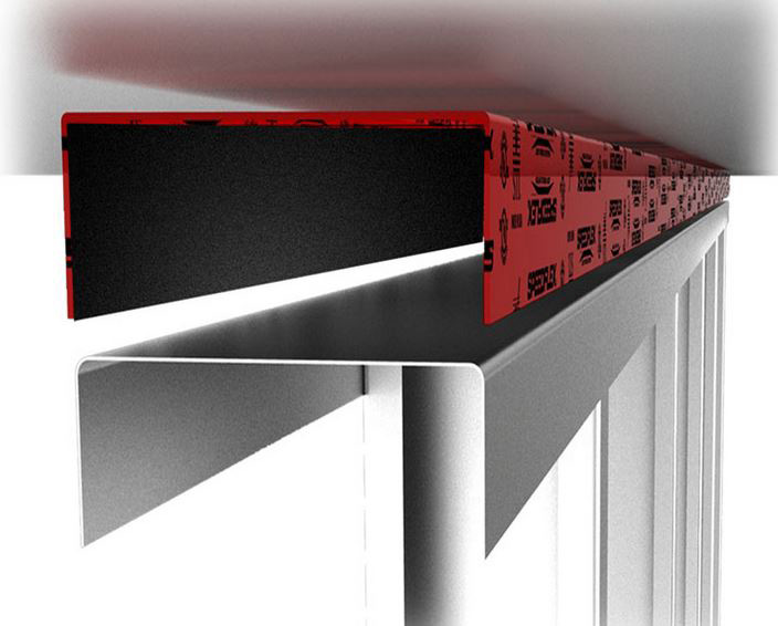
One of several options for treating construction joints, firestop top gaskets, such as the one shown, are designed to fit over the ceiling runner.
Manufacturers typically offer details for the most common firestop systems used in the field. Some host platforms allow users to search for systems based on variables such as the size of the penetration, a description of the wall, floor, or ceiling assembly, the type of joint, fire rating, and more.
Some systems are complicated, with several pages of text. In addition, illustrations can be confusing and don’t always include optional criteria. Here, manufacturer representatives are the architect’s friend. These knowledgeable experts can help find the correct system quickly, saving valuable time and helping avoid costly mistakes.
Construction Documents
Although the IBC does not specifically require firestop systems to be included on CDs, some jurisdictions do require it. At minimum, construction documents should include a schedule of firestop systems by application type (this may be a simple Excel table), along with firestop details and specifications.
Some architects provide a full set of firestop systems for penetrations, joints, and perimeter containments on each set of plans, while others include a limited number of typicals on their drawings. Some include standard wall details but exclude MEP penetrations. Still others choose to make firestop a deferred submittal and let contractors choose appropriate systems for the architect to review. Following the CSI 3-part specification format, commonly used in construction documentation, simplifies communication among team members and ensures code compliance is “baked in” to CDs, as these reference current codes and standards and other requirements relevant to the project.
While it may be common to cut and paste specifications from a previous project, this is not a best practice. Firestopping is too important for life safety, property protection, and legal liability. That said, it can be challenging to determine the appropriate level of detail to include in drawings. Here, refer to the IBC language, which states that “…Construction documents shall be of sufficient clarity to indicate the location, nature, and extent of the work proposed and show in detail that it will conform to the provisions of this code…as determined by the building official.” Clear, detailed construction documents not only protect the architect from liability, but they also help ensure correct project execution and code compliance. They also send a strong message about intent to inspectors.
In any case, taking advantage of available tools such as MasterSPec and RIB SpecLink and partnering with manufacturers can help smooth the process and help create clear, well-written, and accurate specs.
Special Inspections
Building codes require special inspections for firestopping systems in certain buildings. During these inspections, a third-party qualified inspector verifies that the firestop systems installed in a building meet the required standards and are compliant with the appropriate codes.
Since the 2012 International Building Code, special inspection of firestopping has been required for high-rise buildings over 75 feet in height and buildings assigned to risk categories III and IV. These include hospitals, emergency shelters, large schools, and other essential facilities that must remain operational during emergencies. As of the 2021 IBC, special inspections are also required for Group R occupancies when the occupant load exceeds 250. These include large residential buildings such as high-rise apartments and hotels. In all of these cases, special inspections help ensure that passive fire protection systems in these critical and high-occupancy buildings will function as designed during emergencies.
Although special inspections have been required by the IBC since 2012, enforcement has been uneven across jurisdictions. More recently, however, enforcement has been ramping up, as awareness of the importance of firestopping grows and as the number of trained and qualified inspectors increases.
Architects can reduce costly project delays by anticipating inspection requirements during the design phase. Clearly documenting firestop systems on construction drawings and in specifications can go a long way toward ensuring compliance.
Understanding Special Inspection Standards
During an inspection, the inspector is looking for missing material, making sure all penetrations and joints are completely sealed. They are also validating that the materials, such as caulks and collars, match the tested system design and that they are properly installed at the correct depth and thickness. Finally, inspectors may look for firestops that have been damaged or modified since they were initially installed. Often, this occurs during routine maintenance or tenant improvements.
ASTM has published two standards governing these special inspections. On-Site Inspection of Installed Fire Stops for both penetrations and joints: ASTM E2174: Standard Practice for On-Site Inspection of Installed Firestop Systems, covers penetrations and membrane penetrations, while ASTM E2393: Standard Practice for On-Site Inspection of Installed Fire Resistive Joint Systems and Perimeter Fire Barriers, applies to joints and perimeter containments.
Penetrations: ASTM E2174 calls for inspectors to witness a minimum of 10 percent of each type of firestop system being installed. Alternatively, the inspector may conduct a post-installation inspection that involves the destructive verification and repair of at least 2 percent of each type of firestop system per floor or 10,000 square feet of area. The project’s authorizing agency may determine the types of firestop systems and the number of each type to be inspected. This determination is based on several factors, including penetrant type, the firestop system(s) involved, and the rated substrate.
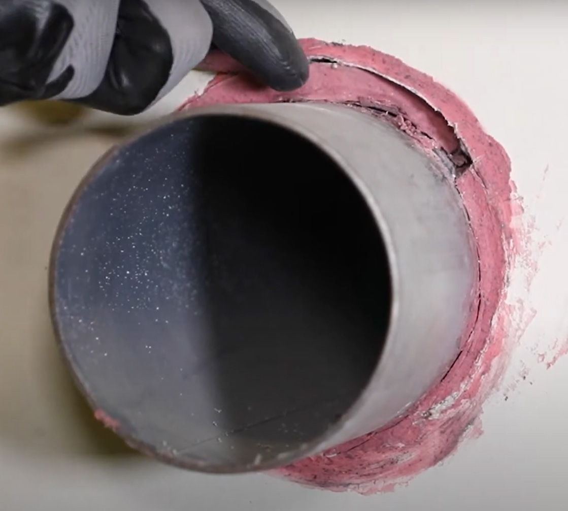
Destructive testing, or verification, according to ASTM E2174, requires the inspector to remove the firestop material to make sure that it was installed using the correct material at the proper depth.
Joints: ASTM E2393 requires the inspector to witness a minimum of 5 percent of the total linear feet of the type of joint system being installed. As an alternative, the inspector may conduct a post-installation inspection that involves the destructive testing and repair of at least one sample per system for every 500 linear feet. Here again, the authorizing agency may determine the types of fire-resistant joint systems and the number of each type to be inspected. This determination is based on joint type, firestop system(s), and the substrate in question.
In both cases, ASTM E2174 and E2393 stipulate that the inspector shall not be a competitor of the installer, contractor, manufacturer, or supplier of any material being inspected. Throughout the inspection process, the inspector must document and report the findings, ensuring that there is a record of compliance for the authority having jurisdiction (AHJ). This documentation is critical for code compliance and to demonstrate that the building meets all the necessary safety requirements.
Common Deficiencies and Coordination Challenges
Newer code requirements, particularly the stipulation for special inspections for passive fire protection, have led to a rise in qualified inspectors. In turn, this has led to increasing scrutiny of installed firestop inspections, as inspectors are catching noncompliance issues that may have gone undetected in the past.
While certainly no contractor or project owner wants to be out of compliance, the bigger issue is that when firestop systems are incorrectly specified or installed, they compromise the performance and life safety of the building.
Let’s look at some common reasons inspections fail.
The first issue happens at the plan review stage. A surefire way to show compliance is to provide specific tested/listed systems for each specific application. If plans do not provide this information, the inspector must confirm compliance in the field. This can be difficult, as systems are difficult to access and inspect after the fact.
Another common issue is that construction drawings conflict with specifications—for example, the product named in the specification may be different from the one on the drawings, leading to confusion about which is correct. Another coordination issue arises when firestop requirements conflict with MEP spec sections. The solution here is to direct MEP consultants to the firestopping requirements in Division 07 84 00.
Cutting and pasting firestop system specifications from previous projects to the current one is a common practice, but it can lead to costly mistakes and non-compliance. Codes change, standards are updated, and new products and construction methods are constantly being introduced. To avoid issues, ask a trusted manufacturer’s representative to review and update specs. Include in the specification when special inspections are required—i.e., for high-rise buildings and those in Risk Categories III and IV.
Still another common issue arises when systems from several manufacturers are specified. Remember, these systems are proprietary and list specific products from specific manufacturers. Substitutions are not allowed, as the product used in the field may have different properties than the product in the listed system. To reduce confusion and possible code violations, use systems from as few manufacturers as possible.
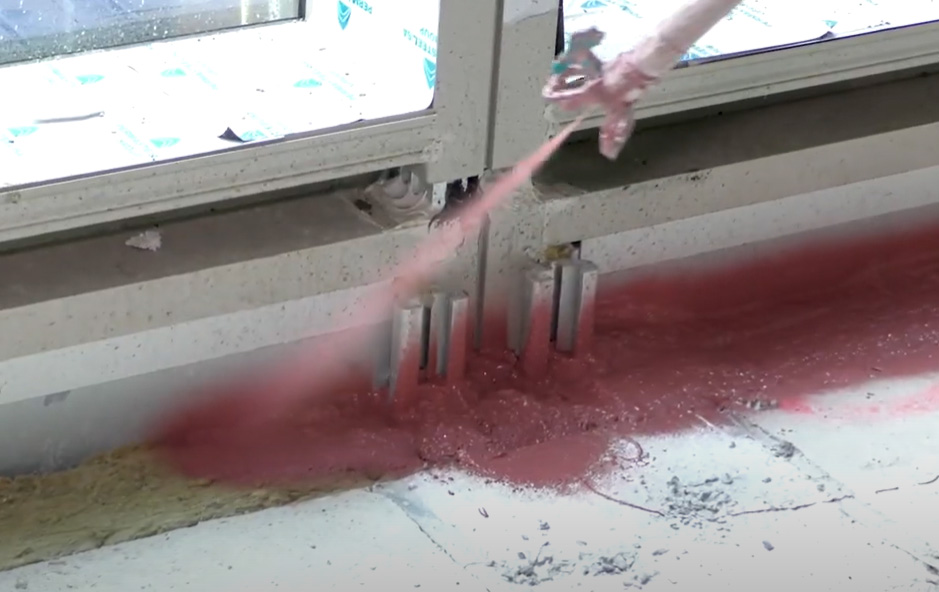
It’s important to use the exact product named in listed systems–in this case, a firestop sealant being sprayed over mineral wool–and to ensure adequate coverage.
Specific Non-Compliance Issues
Inspectors encounter a range of non-compliance issues on jobsites. Rather than list all of them, let’s consider a few common examples.
Fastener schedules. If the fastener schedule is not followed for penetration systems firestopped with intumescent materials, the system may fail to maintain the fire barrier. When a penetrant is exposed to heat and begins to melt or deform, the material may pull away from the substrate if there aren’t enough fasteners to hold it in place.
Inadequate firestop material. If the installer skimps on material, it may not achieve the required depth or volume. Note that tested systems list the minimum amount of firestop material that should be applied; sealant and spray products may reduce in thickness due to off gassing curing. UL maintains percentage shrinkage of sealants and sprays for each manufacturer’s products online for installers, specifiers, and inspectors to reference.
Incorrect firestop material. In the past, it was common practice for a contractor to use red fire caulk for every penetration, without any certification that the material was tested to the required standard for the code-mandated hourly fire rating. The false truism of “Red is right” is not only incorrect, but it is also an unsafe practice, exposing contractors as well as facilities in the event of a fire. Color is not the most important quality, and not all firestop caulk is red!
Scab patching. Sometimes a contractor will use a small piece of gypsum board to cover a hole in a fire-rated assembly. This practice is known as scab patching, and here again, it does not constitute a system that has been certified to restore the integrity of a fire-resistive assembly.
The examples above are just a few of the many issues qualified inspectors encounter in the field. What they have in common is either failure to firestop using a listed system or failure to carefully follow the requirements of a listed system. Good documentation, early planning, and coordination can help avoid these problems.
Designing for Lifecycle Performance
A common misconception is that firestop compliance is only about passing inspection at the end of construction. In reality, firestop systems should be designed, detailed, and documented with the full lifecycle of the building in mind. This is especially important in facilities such as hospitals, where ongoing maintenance, renovations, above-ceiling work, and system upgrades can disturb protected assemblies and trigger future audits, inspections, or compliance reviews.
Certain design and specification strategies support durability, inspection readiness, and reduced lifecycle risk. At the heart of these strategies is the goal of continuous compliance. Here, project teams approach firestop not just as a component of buildings that passes inspection at installation, but as a system designed to remain compliant over time, especially in buildings that undergo frequent changes. In all cases, success depends on early coordination among the design team, subcontractors, and quality control teams well before inspection occurs.
“In many buildings, especially healthcare facilities, firestop compliance does not end when the certificate of occupancy is issued,” says John Zalepka, Director of Training & Industry Engagements, Specified Technologies Inc. “A well-coordinated approach helps support not only initial inspection, but also the ongoing maintenance, renovations, and audits that occur throughout the life of the building.”
Let’s look at some specific strategies that support continued compliance.
Take a unified approach. Too often, the design and construction teams are burdened with initial compliance of passive fire protection, when the ultimate responsibility lies with ownership. Lifecycle compliance is much more achievable when the goal is defined across departments, including designers and contractors, subcontractors, facilities, ownership, and IT. This way, everyone is working toward the same expectation of performance. The compliance objective should be defined up front, documented in policy and procedure, reinforced in specifications, and carried into procurement and construction. From there, every partner is held to that standard and that goal. When that alignment exists, compliance becomes intentional instead of accidental; proactive instead of reactive.
Design with intent. Continuous compliance starts with specifications. When architects specify for lifecycle performance, rather than speed and convenience, they eschew generic specifications in favor of solutions that are meant to be re-entered, inspected, and maintained without degrading performance. This requires selecting specific firestop systems rather than categories. The architect must also be willing to state clearly that no substitutions are allowed when they perceive potential lifecycle risk. Consulting with firestop manufacturers on specifications can make this task easier and help accomplish the goal of lifecycle compliance.
Value engineer for the full lifecycle. Value engineering is a necessary exercise to ensure projects stay within budgets; however, when it comes to firestop systems, it’s crucial that value engineering does not compromise compliance in the short or long term. In this case, the cost of a product should not be the overriding factor; rather, designing for the building’s lifecycle will drive choices that cost less over the building’s life. Choosing a less costly product may lead to deferred maintenance costs, ultimately affecting the building’s operational budget. More importantly, a decision based on cost alone could compromise life safety and the protection of the building.
Construct with intent. Making changes during construction can lead to costly delays; however, with proper coordination, planning, and documentation, these can be avoided. During the construction phase, the pre-construction risk assessment, or PCRA meeting, is a crucial tool for achieving both initial and continued compliance. These meetings serve as a critical point of coordination. This is the time to discuss firestop scope and responsibilities, workflow and scheduling, documentation requirements, and inspection requirements. Involving the architect, general contractor, subcontractors, AHJ, and firestop manufacturer early helps ensure a consistent understanding of system requirements, installation methods, and quality control measures.
Subcontractors should be included in these meetings, as many trades contribute to final compliance. For example, drywall contractors may compromise the top wall joint if they don’t build to the assembly rating, and utility subcontractors may inadvertently cut the wrong opening size for a firestop system. This meeting can help ensure everyone is on the same page and committed to compliance.
Partner with manufacturers. Firestop manufacturers are the industry authorities on barrier compliance. Partnering with a manufacturer that provides a comprehensive training library and support can enhance the quality of construction, the performance of passive fire protection, and avoid non-compliance. Training on topics that are relevant to code compliance and installation of UL assemblies can empower those directly or indirectly involved with the construction of fire barriers. And remember to bring in firestop manufacturers early. Typically, these experts are brought in after an issue arises, making it difficult to resolve while maintaining the schedule and budget.
Some firestop manufacturers also have digital plugins for Autodesk Revit, like firestop clash management tools, that help automate the process of identifying where firestopping is required in a BIM model and then recommend the correctly tested firestop systems for those conditions.
In simple terms, it helps BIM coordinators, designers, and contractors answer questions like:
- “Where do penetrations intersect rated walls or floors?”
- “What UL-listed firestop system should be used here?”
Tools like these reduce coordination errors, standardize firestop designs, improve code compliance, and speed up BIM coordination.
Create a Barrier Management Program. Managing barriers is a complex task, especially in buildings such as healthcare facilities. Here, a Barrier Management Program is an essential tool. A BMP identifies all fire-rated and non-rated assemblies, every type of penetrant, and all joint types. The program clarifies the responsibilities of vendors who supply systems, the contractors who are responsible for correctly installing them, and maintenance personnel, who are responsible for maintaining them over time. The goals of a BMP are to ensure regulatory compliance, take a proactive approach with inspectors, reduce errors during construction, reduce operating costs and property loss, and, most importantly, ensure life safety for all building occupants.
Some manufacturers also pair barrier management programs with digital firestop locating tools that offer digital documentation, inspection, and tracking to manage firestop systems and other life-safety components throughout construction and facility operations. These applications typically work on phones, tablets, and desktops and use interactive floor plans to visually map and manage installed firestop systems.
In practical terms, it helps contractors, inspectors, facility managers, and building owners answer questions like:
- “Where are all the firestopped penetrations in this building?”
- “Which UL system was installed at this location?”
These types of tools offer digital field management and compliance in a single platform that easily tracks firestopping and life-safety systems throughout a building’s lifecycle.
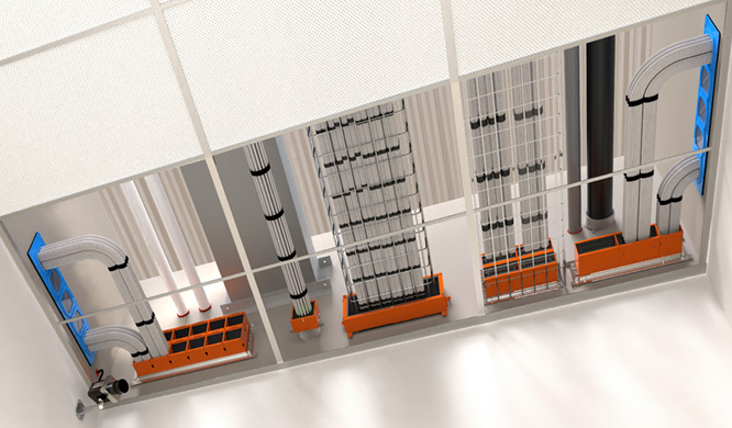
Firestop pathways designed for cables can accommodate changes while remaining compliant.
Conclusion
Firestop systems are a crucial part of passive fire protection and a comprehensive life-safety strategy in buildings. The rise in special inspections of these systems should not be seen as a threat or a hurdle, but an opportunity to shift from reactive correction to proactive coordination. The best outcomes happen when design teams, contractors, and inspectors are aligned early so that tested and listed systems can be properly selected, installed, and verified. When teams understand what inspectors are looking for, they can reduce costly rework and improve the long-term performance of passive fire protection systems. Design professionals have a key role to play through informed specification and coordination. By partnering with trusted manufacturers, they can ensure the best solutions are specified and installed, not only for the initial project, but for years to come.
Andrew A. Hunt is Vice President of Confluence Communications and specializes in writing, design, and production of articles and presentations related to sustainable design in the built environment. In addition to instructional design, writing, and project management, Andrew is an accomplished musician and voice-over actor, providing score and narration for both the entertainment and education arenas. www.confluencec.com; www.linkedin.com/in/andrew-a-hunt-91b747