Photo courtesy of ESI Total Fuel Management
Planning for power resilience means shielding your design from the unpredictable.
The loss of power is unpredictable, disruptive, and expensive. There are many motivations for commercial buildings to include backup power systems. About 75% of commercial businesses in the United States currently have backup generators.
Weather has always been a leading cause of outages, and weather-related power outages are on the rise. From 2000 to 2023, about 80% of major power outages in the U.S. were due to weather events. The number of such outages in the last decade (2014-2023) was double that of the first decade of the century. Most weather-related outages were caused by severe weather (58%), winter storms (23%), and tropical cyclones, including hurricanes (14%). The states with the most reported weather-related power outages (2000-2023) were Texas (210), Michigan (157), California (145), North Carolina (111), and Ohio (88).
Beyond the impacts of weather, the aging national infrastructure brings its own challenges, including distribution and transmission outages. Distribution outages are local issues specific to the utility that provides power directly to customer meters. They include events such as power line, transformer, and substation failures, rolling outage events, and public safety power shutoff events. Transmission outages are power grid issues that affect distribution utilities. They include events such as transmission line failures, power plant failures, and grid operator-directed power curtailments. Rolling outages are used when a utility must disconnect electric customers to lower overall grid loads. The utility shuts off specific circuits for a set amount of time, then turns them back on while shutting down the next set of electric circuits. Finally, when the amount of power being generated cannot meet current energy demand, power grid operators will call for Load Shedding or Power Curtailments. They direct the distribution utilities on their grid to lower the load on the grid; this is done mostly by increasing the cost of power, forcing power outages, or implementing rolling outages.
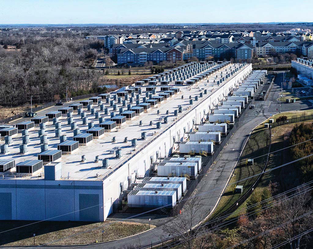
However, for mission-critical facilities and data centers, a power outage, even for a fraction of a second, is a very bad thing. If local power goes out, or “sags,” the facility must continue operations unaffected. Data centers, in particular, are looking for 99.99999% uptime (seven 9s), which is much higher than the customary five or even six 9s of high-uptime reliability systems. Downtime is costly: collaboration and messaging software company Slack surrendered $8.2 million in revenue after its work-communications platform went down for about two hours over a 92-day period in 2019. The multi-million-dollar sum was issued in credits to users after the company achieved only 99.9% service uptime for the quarter.
Backup Power in Design
The National Electric Code (NEC) is also known as “NFPA 70” or the National Fire Protection Association’s Standard 70. The NEC addresses the installation of electrical components; signaling and communications systems; and optical fiber systems in commercial, residential, and industrial occupancies. It also lays out requirements for backup power.
“Critical operation power systems” (COPS) are the newest classification of backup power (NEC Article 708) for systems, operations, or facilities designated by local, state, and federal government as “mission critical.” These systems are required in facilities that, if destroyed or incapacitated, would disrupt national security, the economy, or public health or safety. Government agencies or Authorities Having Jurisdiction (AHJ) can designate any critical facility, such as police stations, fire stations, emergency call centers, telecommunications carriers, data centers, and other critical infrastructure, as a “designated critical operations area” to comply with Article 708. There are also additional commissioning requirements for COPS.
For COPS facilities, emergency and standby power systems must be maintained in accordance with NFPA 110 and NFPA 111, such that the system is capable of supplying service within the time specified for the type and duration required. Inspection, testing, and maintenance of emergency and standby power systems for COPS must be in accordance with an approved schedule (1203.4.2) established upon completion and approval of the system installation. Additionally, records of the inspection, testing, and maintenance of emergency and standby power systems are required and must be maintained. Switch maintenance and emergency power systems, including all appurtenant components, shall be inspected and tested under load in accordance with NFPA 110 and NFPA 111.
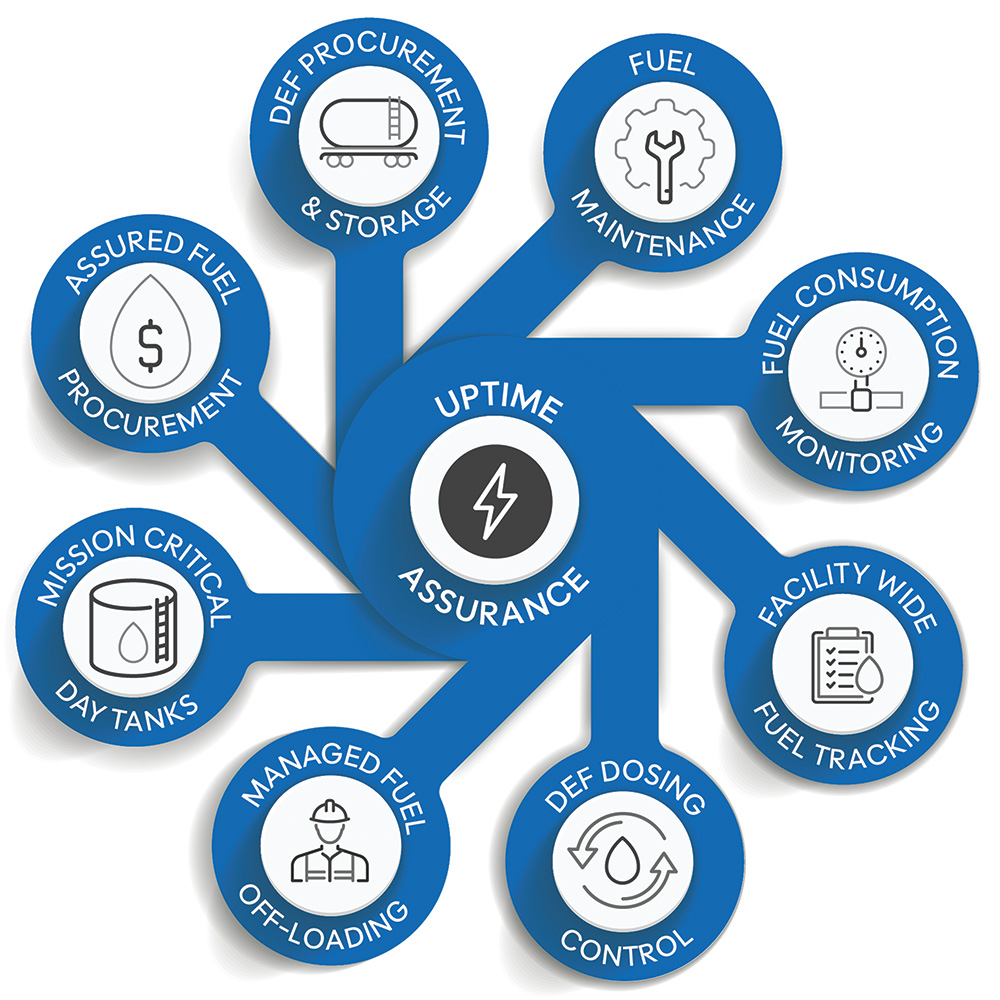
Image courtesy of ESI Total Fuel Management
Designing projects that readily incorporate backup power systems involves thinking through many aspects of layout and maintenance.
Designing for the Unpredictable: Layout Considerations
The design of backup power has evolved significantly, shifting from underground fuel storage and large centralized systems to enclosure-based generators. While this transition offers construction and cost efficiencies, it introduces new challenges. As the number of COPS and other facilities required to supply backup power grows, considering logistics for these systems is paramount.
The first recommended step to implement the needed resilience for a critical infrastructure facility or site is to develop a risk management plan. Development of a risk management plan must be guided by Project Management Institute and FEMA recommendations. Some of the key resilient power goals that should be considered include assessing the need for uninterrupted power. Is power needed continuously, 24/7? Can power be lost for tens of milliseconds, seconds, minutes, or even hours? For what length of time will power be required? Must power be maintained for days, weeks, or even months? What is the cost, including the Value of Lost Load (VoLL: the estimated amount that customers receiving electricity with firm contracts would be willing to pay to avoid a disruption in their electricity service), if power is lost? Finally, should preparations cover just known moderate and high-probability risks, or should they also include low-probability risks or even black swan events?
To reduce costs and improve resiliency, implementation of best practices and guidelines should be performed holistically. Cybersecurity, physical security, electro-magnetic security, and fuel considerations could impact the selection and location of the backup power generation design, so these best practices should be considered in unison to ensure that an appropriate, resilient power solution is identified, implemented, and maintained.
When laying out the design for backup power, it is critical that all national, state, and local codes for the design and location of all generators are followed. The generator must be installed in a location that allows proper exhaust. Local zoning regulations may prescribe minimum distances from the generator to property lines or to other nearby structures. Distances from windows, fresh air intakes, patios, and outdoor amenity spaces will also be reviewed as part of the building permit. Additionally, generators should be in a location away from potential water intrusion from gutters and sprinklers.
The physical design of the facility, whether new or existing, should be assessed to verify that there is enough room for the installation of new equipment, which may include batteries, UPS systems, and generators. Planning for fueling and maintenance access is also critical. Traditional backup power systems used underground fuel storage tanks (USTs) with centralized generator systems, allowing for efficient refueling via gravity-fed transport trucks. However, modern designs now favor enclosure-based generators, often arranged in large clusters with individual fuel tanks. This shift has created new logistical challenges in fuel access, delivery speed, and site resiliency. Enclosure-based generators are often surrounded by fences, transformers, or other equipment, significantly reducing truck access. Poorly designed facilities can prevent adequate access, forcing fuel deliveries to utilize long hoses, increasing the risk of hose damage and spills.
The size of the fuel storage container is the first maintenance-related decision designers confront in layout. To calculate the number of gallons of fuel needed, the power manager or engineer should estimate the average load per hour during a multi-day power outage and the generator efficiency over each of these hourly estimates. The amount of fuel used per hour can then be calculated, and the overall usage over a 24-hour period can be determined. Lastly, the storage required can easily be calculated by multiplying the estimated fuel used in a 24-hour period by the number of days that guaranteed power is required. An estimate of the storage required is available in FEMA’s June 2017 Power Outage Incident Annex to the Response and Recovery Federal Interagency Operational Plans under Figure 3, Daily Fuel Consumption by Critical Facilities.
Once the minimum fuel storage size is known, the next major decision relates to location: whether to store the container aboveground or underground. In many places, underground storage is increasingly not feasible. Buried or mostly buried tanks are prone to water leakage at the fuel supply cover assembly and from corrosion if the tank is made of metal. For buried tanks, consider fiberglass or ceramic, or protect the metal to ensure resilient fuel storage. Although condensation is less of an issue with underground tanks than aboveground systems, the tanks will still have a difference in temperature between the bottom and top of the tank, which will lead to condensation forming on the tank walls and dropping to the tank bottom. Over time, this water will accumulate and provide an environment for fungal and microbial growth. Because it is very difficult to inspect underground tanks, automated measurements must be included to ensure that there is no leakage.
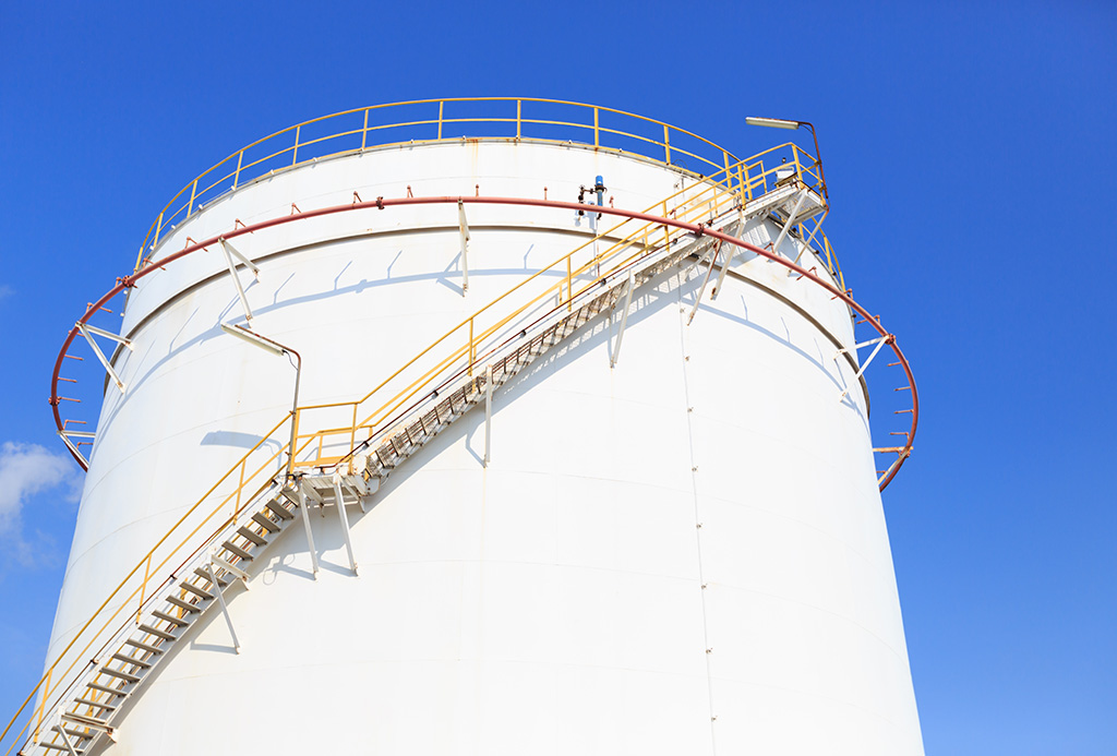
Photo courtesy of ESI Total Fuel Management
Aboveground storage tank. Considerations for tank location should include site conditions, containment, protection, and maintenance.
For storage placed above ground, the lack of ground insulation, changes in temperature, and the amount of sunshine will cause the fuel inside the tank to expand and then contract daily. This expansion/contraction cycle can lead to condensation forming on the walls of the tank and settling to the bottom, providing a growth medium. This can cause fuel in aboveground tanks to have a shorter shelf life than underground tanks. Aboveground storage tanks (AST) often preclude fuel delivery by larger-capacity, gravity-fed tanker trucks. Lastly, in extremely cold climates, kerosene will need to be blended into the diesel fuel to prevent freezing during the winter.
The location of any storage tank should endeavor to keep fuel in a dry, cool location without water, humidity, or oxygen being able to enter the storage container. Tanks should also have a well-defined low point where water can collect and be drained. If the generator fuel is diesel, the storage container should ensure that the diesel fuel will not contact zinc, copper, or metal alloys. These metals will quickly react with diesel fuel to form unstable compounds. Even dust with traces of these elements can be an issue.
Resilience for power is defined as the ability to prepare for and adapt to changing conditions and withstand and recover rapidly from disruptions; it includes the ability to withstand and recover from deliberate attacks, accidents, or naturally occurring threats or incidents. Design, process, and maintenance ensure that a resilient power architecture is implemented effectively and efficiently and that the power-related equipment and supplies are maintained properly. This is of critical importance as many facilities have not developed an EAP (Emergency Action Plan) that covers out-of-the-ordinary events like riots and force majeure events.
Fuel resiliency is critical to maintaining data center uptime in an industry increasingly reliant on high-density power and AI-driven workloads. As design trends evolve, engineers and operators must rethink fuel logistics, implement smart infrastructure, and stay ahead of regulatory changes to ensure uninterrupted operations.
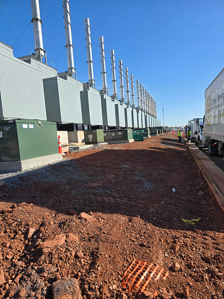
Photo courtesy of ESI Total Fuel Management
Designing resilience into a facility means thinking through resilience for backup power systems. This includes ensuring fuel logistics and the ability to maintain and monitor systems.
Photo courtesy of ESI Total Fuel Management
Planning for power resilience means shielding your design from the unpredictable.
The loss of power is unpredictable, disruptive, and expensive. There are many motivations for commercial buildings to include backup power systems. About 75% of commercial businesses in the United States currently have backup generators.
Weather has always been a leading cause of outages, and weather-related power outages are on the rise. From 2000 to 2023, about 80% of major power outages in the U.S. were due to weather events. The number of such outages in the last decade (2014-2023) was double that of the first decade of the century. Most weather-related outages were caused by severe weather (58%), winter storms (23%), and tropical cyclones, including hurricanes (14%). The states with the most reported weather-related power outages (2000-2023) were Texas (210), Michigan (157), California (145), North Carolina (111), and Ohio (88).
Beyond the impacts of weather, the aging national infrastructure brings its own challenges, including distribution and transmission outages. Distribution outages are local issues specific to the utility that provides power directly to customer meters. They include events such as power line, transformer, and substation failures, rolling outage events, and public safety power shutoff events. Transmission outages are power grid issues that affect distribution utilities. They include events such as transmission line failures, power plant failures, and grid operator-directed power curtailments. Rolling outages are used when a utility must disconnect electric customers to lower overall grid loads. The utility shuts off specific circuits for a set amount of time, then turns them back on while shutting down the next set of electric circuits. Finally, when the amount of power being generated cannot meet current energy demand, power grid operators will call for Load Shedding or Power Curtailments. They direct the distribution utilities on their grid to lower the load on the grid; this is done mostly by increasing the cost of power, forcing power outages, or implementing rolling outages.
However, for mission-critical facilities and data centers, a power outage, even for a fraction of a second, is a very bad thing. If local power goes out, or “sags,” the facility must continue operations unaffected. Data centers, in particular, are looking for 99.99999% uptime (seven 9s), which is much higher than the customary five or even six 9s of high-uptime reliability systems. Downtime is costly: collaboration and messaging software company Slack surrendered $8.2 million in revenue after its work-communications platform went down for about two hours over a 92-day period in 2019. The multi-million-dollar sum was issued in credits to users after the company achieved only 99.9% service uptime for the quarter.
Backup Power in Design
The National Electric Code (NEC) is also known as “NFPA 70” or the National Fire Protection Association’s Standard 70. The NEC addresses the installation of electrical components; signaling and communications systems; and optical fiber systems in commercial, residential, and industrial occupancies. It also lays out requirements for backup power.
“Critical operation power systems” (COPS) are the newest classification of backup power (NEC Article 708) for systems, operations, or facilities designated by local, state, and federal government as “mission critical.” These systems are required in facilities that, if destroyed or incapacitated, would disrupt national security, the economy, or public health or safety. Government agencies or Authorities Having Jurisdiction (AHJ) can designate any critical facility, such as police stations, fire stations, emergency call centers, telecommunications carriers, data centers, and other critical infrastructure, as a “designated critical operations area” to comply with Article 708. There are also additional commissioning requirements for COPS.
For COPS facilities, emergency and standby power systems must be maintained in accordance with NFPA 110 and NFPA 111, such that the system is capable of supplying service within the time specified for the type and duration required. Inspection, testing, and maintenance of emergency and standby power systems for COPS must be in accordance with an approved schedule (1203.4.2) established upon completion and approval of the system installation. Additionally, records of the inspection, testing, and maintenance of emergency and standby power systems are required and must be maintained. Switch maintenance and emergency power systems, including all appurtenant components, shall be inspected and tested under load in accordance with NFPA 110 and NFPA 111.
Image courtesy of ESI Total Fuel Management
Designing projects that readily incorporate backup power systems involves thinking through many aspects of layout and maintenance.
Designing for the Unpredictable: Layout Considerations
The design of backup power has evolved significantly, shifting from underground fuel storage and large centralized systems to enclosure-based generators. While this transition offers construction and cost efficiencies, it introduces new challenges. As the number of COPS and other facilities required to supply backup power grows, considering logistics for these systems is paramount.
The first recommended step to implement the needed resilience for a critical infrastructure facility or site is to develop a risk management plan. Development of a risk management plan must be guided by Project Management Institute and FEMA recommendations. Some of the key resilient power goals that should be considered include assessing the need for uninterrupted power. Is power needed continuously, 24/7? Can power be lost for tens of milliseconds, seconds, minutes, or even hours? For what length of time will power be required? Must power be maintained for days, weeks, or even months? What is the cost, including the Value of Lost Load (VoLL: the estimated amount that customers receiving electricity with firm contracts would be willing to pay to avoid a disruption in their electricity service), if power is lost? Finally, should preparations cover just known moderate and high-probability risks, or should they also include low-probability risks or even black swan events?
To reduce costs and improve resiliency, implementation of best practices and guidelines should be performed holistically. Cybersecurity, physical security, electro-magnetic security, and fuel considerations could impact the selection and location of the backup power generation design, so these best practices should be considered in unison to ensure that an appropriate, resilient power solution is identified, implemented, and maintained.
When laying out the design for backup power, it is critical that all national, state, and local codes for the design and location of all generators are followed. The generator must be installed in a location that allows proper exhaust. Local zoning regulations may prescribe minimum distances from the generator to property lines or to other nearby structures. Distances from windows, fresh air intakes, patios, and outdoor amenity spaces will also be reviewed as part of the building permit. Additionally, generators should be in a location away from potential water intrusion from gutters and sprinklers.
The physical design of the facility, whether new or existing, should be assessed to verify that there is enough room for the installation of new equipment, which may include batteries, UPS systems, and generators. Planning for fueling and maintenance access is also critical. Traditional backup power systems used underground fuel storage tanks (USTs) with centralized generator systems, allowing for efficient refueling via gravity-fed transport trucks. However, modern designs now favor enclosure-based generators, often arranged in large clusters with individual fuel tanks. This shift has created new logistical challenges in fuel access, delivery speed, and site resiliency. Enclosure-based generators are often surrounded by fences, transformers, or other equipment, significantly reducing truck access. Poorly designed facilities can prevent adequate access, forcing fuel deliveries to utilize long hoses, increasing the risk of hose damage and spills.
The size of the fuel storage container is the first maintenance-related decision designers confront in layout. To calculate the number of gallons of fuel needed, the power manager or engineer should estimate the average load per hour during a multi-day power outage and the generator efficiency over each of these hourly estimates. The amount of fuel used per hour can then be calculated, and the overall usage over a 24-hour period can be determined. Lastly, the storage required can easily be calculated by multiplying the estimated fuel used in a 24-hour period by the number of days that guaranteed power is required. An estimate of the storage required is available in FEMA’s June 2017 Power Outage Incident Annex to the Response and Recovery Federal Interagency Operational Plans under Figure 3, Daily Fuel Consumption by Critical Facilities.
Once the minimum fuel storage size is known, the next major decision relates to location: whether to store the container aboveground or underground. In many places, underground storage is increasingly not feasible. Buried or mostly buried tanks are prone to water leakage at the fuel supply cover assembly and from corrosion if the tank is made of metal. For buried tanks, consider fiberglass or ceramic, or protect the metal to ensure resilient fuel storage. Although condensation is less of an issue with underground tanks than aboveground systems, the tanks will still have a difference in temperature between the bottom and top of the tank, which will lead to condensation forming on the tank walls and dropping to the tank bottom. Over time, this water will accumulate and provide an environment for fungal and microbial growth. Because it is very difficult to inspect underground tanks, automated measurements must be included to ensure that there is no leakage.
Photo courtesy of ESI Total Fuel Management
Aboveground storage tank. Considerations for tank location should include site conditions, containment, protection, and maintenance.
For storage placed above ground, the lack of ground insulation, changes in temperature, and the amount of sunshine will cause the fuel inside the tank to expand and then contract daily. This expansion/contraction cycle can lead to condensation forming on the walls of the tank and settling to the bottom, providing a growth medium. This can cause fuel in aboveground tanks to have a shorter shelf life than underground tanks. Aboveground storage tanks (AST) often preclude fuel delivery by larger-capacity, gravity-fed tanker trucks. Lastly, in extremely cold climates, kerosene will need to be blended into the diesel fuel to prevent freezing during the winter.
The location of any storage tank should endeavor to keep fuel in a dry, cool location without water, humidity, or oxygen being able to enter the storage container. Tanks should also have a well-defined low point where water can collect and be drained. If the generator fuel is diesel, the storage container should ensure that the diesel fuel will not contact zinc, copper, or metal alloys. These metals will quickly react with diesel fuel to form unstable compounds. Even dust with traces of these elements can be an issue.
Resilience for power is defined as the ability to prepare for and adapt to changing conditions and withstand and recover rapidly from disruptions; it includes the ability to withstand and recover from deliberate attacks, accidents, or naturally occurring threats or incidents. Design, process, and maintenance ensure that a resilient power architecture is implemented effectively and efficiently and that the power-related equipment and supplies are maintained properly. This is of critical importance as many facilities have not developed an EAP (Emergency Action Plan) that covers out-of-the-ordinary events like riots and force majeure events.
Fuel resiliency is critical to maintaining data center uptime in an industry increasingly reliant on high-density power and AI-driven workloads. As design trends evolve, engineers and operators must rethink fuel logistics, implement smart infrastructure, and stay ahead of regulatory changes to ensure uninterrupted operations.
Photo courtesy of ESI Total Fuel Management
Designing resilience into a facility means thinking through resilience for backup power systems. This includes ensuring fuel logistics and the ability to maintain and monitor systems.
Solving Fueling Logistic Requirements
Design professionals, engineers, and general contractors are forced to focus on the physical building features and functionality. Many times, these professionals are missing the critical information necessary to design and build the backup generators and associated fuel tanks in a manner that takes into consideration the complexities of fuel logistics.
Generators are essential to ensure continuity when the electric power grid is disrupted. Generators convert the mechanical energy generated by the engine into electricity using an alternator. Per ISO 8528-1, there are four types of generator ratings that can be selected from to match appropriate backup or emergency power needs: emergency standby power, limited time running power, prime running power, and continuous operating power. These ratings delineate running time, load profile, and allowable overload. Assigned generator ratings all assume that proper maintenance is performed.
Diesel is the most common fuel type for emergency and backup generators. Diesel generators tend to be the least expensive, particularly for larger loads. Selecting diesel offers high efficiency when compared with other fuel sources; its efficiency is better than that of gasoline and much better than natural gas/propane. Diesel also has a much higher energy density than natural gas or propane, making it much easier to store and taking up much less space. It is widely available and can be delivered cost-effectively without the need for a pipeline. And like other sources, diesel generators have characteristics that need to be accommodated, including environmental, fuel storage, and maintenance requirements.
For design professionals, there are advantages that can be secured by the initial design. It is important to specify the fuel storage container’s general size, type, and location. For the management team, coordination with design is necessary, as calculations of how much fuel is expected to be used under various scenarios, the estimated fuel that will be available, including anticipated fuel container levels, and how long the fuel will last under the identified scenarios. Sufficient fuel should be guaranteed for all hazards, typically by storing the fuel onsite for the minimum amount of time required. Per Cybersecurity and Infrastructure Security Agency (CISA) guidelines, a Level 1 facility should have enough fuel for 3 days of operation, a Level 2 for seven days, a Level 3 for 30 days, and a Level 4 should store fuel amounts that exceed the needs of a month of operations.
There are challenges to fueling logistics. Reduced storage capacity and increased delivery frequency diminish operational flexibility. More frequent fuel deliveries also increase the risk of supply chain disruptions during emergencies. Additionally, transportation constraints can lead to facility downtime. Most gravity-fed transport trucks (7,500-gallon capacity) do not provide pumping capability, while pump trucks offer a lower capacity (4,200 gallons), requiring twice the number of deliveries.
To overcome these challenges, there are several strategies and services that improve fuel resiliency. First among these is implementing a Fuel Header System in the backup design. A header system allows multiple generators to be fueled from a single access point, eliminating the need for dragging hoses through fences or the excess movement of vehicles. This method may easily reduce fueling time from six hours to one hour. Headers can be manual or automated with mechanical overfill prevention valves.
Adding a pumping skid for transport truck offloading is another design that promotes fuel logistics resilience. Adding a pumping skid allows both meter trucks and transport trucks to offload fuel efficiently. A properly designed system achieves flow rates greater than 300 gallons per minute, reducing delivery time from hours to minutes.
Incorporating a centralized buffer tank provides onsite fuel storage, ensuring availability during fuel shortages. This centralized tank distributes fuel to belly tanks as needed, reducing reliance on external deliveries. New tank and distribution options simplify fuel delivery operations while enhancing a facility’s remote diesel fuel offloading capabilities of above-ground fuel storage tanks. The system accepts fuel from fuel delivery trucks with or without an onboard pump, minimizes fuel spillage during the offloading process, and allows for easy isolation of the fuel pumps.
Advances in diesel storage tank fill systems include automatic closing of tank isolation valves after stoppage of the filling operation or reaching 90% tank capacity. Positive displacement flow meters included within the system for custody transfer applications requiring weights and measures or approved accuracy can be designed to fit specific diesel fuel supply and fuel storage requirements. Different connections are also available to best fit transport or pump trucks from the supplier.
Advances in day-tank engineering design also maximize critical facility uptime and save the organization time, as well as procurement and installation hassles. Unique day-tank solutions arrive onsite completely assembled, sized to facility specifications, and fully tested. Some manufacturers provide these units factory-built and designed to minimize the possibility of leakage. Day-tanks can include advanced data management for seamless compliance with all consumption reporting requirements for Federal and Local air quality permits, such as NOx emission reporting. Consumption monitoring, data reporting, and network communication features can be integrated.
Network-based control panels, using networked distributed control systems, replace long conduit runs, improving installation efficiency and reducing wiring costs. This also enables real-time monitoring and automated tank filling. Both interconnecting and optimizing all fuel-related functions are required to maintain maximum uptime.
Opting for innovative networked control and monitoring systems allows facilities not only to track consumption but further report on engine supply and return flow rates to give instantaneous consumption rates while performing data collection and analytics. This significantly enhances fuel management and reporting capabilities. Monitoring and data systems for backup power empower facility managers to make informed decisions and maintain peak operating system performance prior to, during, and after an emergency event. Multi-function Consumption Monitoring Systems consolidate components on a tight footprint frame and are delivered fully assembled, programmed, and calibrated. Monitoring programs can be stand-alone units or capable of network communication. Optional central data management systems can also be selected to track, log, and display all consumption information from each consumption monitor, funneling the gathered data to one location with customizable reporting capabilities. Manufacturers that use positive displacement flow meter design with temperature compensation eliminate inaccuracies created by vibration, viscosity, temperature, and flow pulsation. This provides accuracy verification of 3 years or 300 hours for top models, with reporting on engine supply and return flow rates, engine supply and return fuel temperature, engine supply and return flow pulsation, instantaneous consumption rates, and non-resettable totals for: consumption, supply flow, and return flow. Selecting a monitoring program also enables full compliance with all consumption reporting requirements for Federal and Local air quality permits.
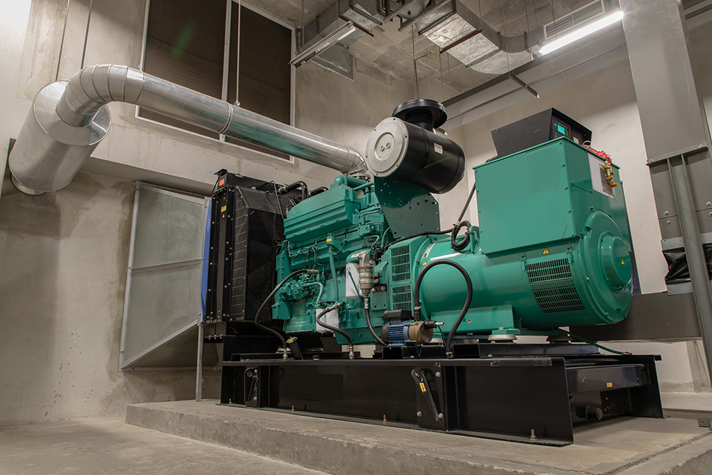
Photo courtesy of ESI Total Fuel Management
Innovations in monitoring and maintenance equipment are helping ensure that generators are functional when called upon.
Designing for Monitoring and Maintenance
Facility continuity and critical operations depend on fuel supply, delivery, quality, storage, consumption, and generator emissions, as well as data collection and management, regulatory reporting, system maintenance, and executive communications. Unfortunately, generators are notorious for failing due to poor maintenance; “during Superstorm Sandy, 50% of hospitals’ emergency generators failed due to maintenance and fuel issues.”
To properly maintain diesel fuel, it is recommended that an industry or government standard be followed, such as MIL-STD-3004-1, DoD Standard Practice Quality Assurance for Bulk Fuels, Lubricants and Related Products. Because of the time required for fuel quality issues to occur, assuming proper storage is implemented, MIL-STD-3004-1 states that a product is considered under long-term storage conditions when held for a period longer than six months without an exchange of at least two-thirds of the tank contents. MIL-STD-3004D states, “product stored without an inventory exchange received into existing inventories of at least two-thirds of the tank content from a different Defense Fuel Support Point (DFSP)/commercial supplier with product that meets quality surveillance requirements within 6 months is considered long-term storage.” On top of that, frequent maintenance is particularly important for emergency generators.
Turning the fuel over is important because various elements of the fuel deteriorate over time, so that eventually rehabilitation is required before usage. If rehabilitation is not feasible, the fuel needs to be replaced. A good storage container in a dry, cool, and dark place can make the fuel last much longer. Selecting ceramic tanks means avoiding rust potential.
Best practices for fuel maintenance include specifying filters, including a fuel polishing system, and additives. All of these can significantly extend the life of the fuel. Testing is another important component. Because of the variability in storage containers, storage location, and the weather, fuel testing often needs to occur to determine how to best maintain the fuel. Finally, maintenance of the equipment is essential. Records should be maintained for each diesel generator. Maintenance records should consist of all maintenance activities, failures, errors, causes, and corrective actions for any problems, and test data.
Per MIL-STD-3004-1, maintenance procedures should include the following:
- Buy Quality Fuel – Obtain assurances from the supplier that all components are fully refined to promote stability.
- Check for Water in Tank – Water checks should be made daily on issue tanks or weekly on static tanks, or each time a tank is gauged, whichever occurs first. When water is found, it should be drained as soon as possible.
- Drain Water – Bulk fuel tanks should be drained of water after each product receipt, as well as a minimum of weekly thereafter, and prior to each issue. Floating roof tanks should be checked more frequently during periods of heavy rain or melting snow. Underground fuel tanks should be checked more frequently when the water table is high and during periods of excessive rain or melting snow.
- Keep Tanks Full – Tanks should be kept full to reduce the space for water to condense. Maintaining tanks that are partially empty increases the water build-up and promotes corrosion in the top half of the tank.
- Filter Fuel – Establish a system for filtering the contents of the main storage tank through a recirculating filter system to reduce the potential for problems by removing sediment and gums. This can be made automatic. The filters should be checked and changed at regular intervals. When the filter change interval reaches a certain frequency, then the fuel should be changed.
- Clean Tank – The tank should be emptied and cleaned at least once every 10 years, or more frequently if there is a major contamination.
- Avoid Biodiesel – Do not use biodiesel or biodiesel blends if possible. Biodiesel and blends have a shorter storage life than petroleum-derived diesel and have lower energy content per gallon, which may reduce maximum engine power output.
Understanding HVO
Hydrogenated vegetable oil (HVO) fuel is an additional alternative fuel available in the market. HVO fuel is produced through hydrotreatment, a process involving hydrogenation. This results in a paraffinic hydrocarbon structure, which is chemically different from traditional biodiesel. Biodiesel’s production involves transesterification, leading to a methyl ester chemical structure. This difference in chemical composition impacts various properties, including stability and performance.
Physical Properties
- Cold Flow Properties: HVO fuel has superior cold flow properties, remaining fluid at lower temperatures compared to biodiesel. This makes it more suitable for colder climates.
- Energy Content: Generally, HVO fuel has a higher energy content per volume than biodiesel, translating into better fuel efficiency.
Environmental Impact
- Emission Reductions: While both alternative fuels reduce greenhouse gas emissions compared to fossil diesel, HVO fuel generally offers a greater reduction.
- Sustainability: HVO fuel’s ability to utilize a broader range of feedstocks, including waste and residues, presents a more sustainable option with less impact on food crop demand.
Storage and Handling
- Shelf Life: HVO fuel boasts a longer shelf life due to its stable chemical structure, making it more favorable for long-term storage.
- Compatibility with Infrastructure: HVO’s compatibility with existing diesel infrastructure, without the need for modifications, presents a logistical advantage.
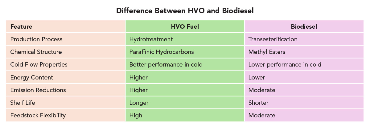
Image courtesy of ESI Total Fuel Management
Comparison of HVO and biodiesel characteristics.
Innovations in Fuel Maintenance
Fuel polishing is a process that cleans and purifies stored fuel, typically diesel, by filtering out contaminants like water, sediment, and microbial growth. A fuel polishing unit can keep the fuel from being contaminated and can fulfill some of the above steps to ensure that the fuel is always ready to use. It uses multiple stages to effectively filter and remove contaminants, including water and microbial growth. The polishing unit can be cost-effectively programmed to run on a regular cycle without human intervention, eliminating the need for chemical stabilizers. Polishing the stored fuel as seldom as once a month provides for a highly extended shelf life of the stored product.
When a polishing unit is not used and it is unfeasible to cycle through the fuel in a timely fashion, additives like stabilizers, metal deactivators, fungicides, or biocides may be needed to improve diesel fuel storage life.
However, new product innovations for storing fuel can prevent diesel generator failure by cleanly and reliably filtering stored diesel fuels and continuously eliminating water, sediment, and microbial build-up through an engineered process. Reliable fuel polishing provides a comprehensive, engineered fuel filtration system to protect stored diesel fuel in standby power systems. The best systems offer end-to-end fuel management solutions that guarantee the quality of fuel entering the system, the maintenance of diesel fuel in the system, and the clean and green removal of water and contaminants at the end of the filtration process. By perfecting the science of fuel and water separation and ensuring that contaminants are not released into the environment, fuel filtering innovations provide green filtration systems that also dramatically reduce total ownership costs. Selection of engineered solutions designed to minimize the potential of leakage is generally accepted as an industry best practice.
Specifying a redundant primary filter set (RPFS) is another step to facilitate continuous operation, minimize risk, and maintain continuity of mission-critical energy loads. RPFS is designed for pressure or vacuum side application to be between the storage tank and the day tank, or to provide filtration from the day tank directly to the engine. The static pressure should not exceed 90 PSI. The factory setting for the filters is 15 PSID. The filter-set is designed to allow the operator to easily switch over between single, large capacity filter housings, enabling a switch from a single clogging filter to a single new filter without interrupting day tank filling. This facilitates continuous operation and minimizes risk to the continuity of mission-critical loads. Innovations in RPFS provide the filter set as a fully assembled, bulkhead-mounted, “plug and play unit.”
An optional remote monitoring package can also be included. Operational conditions monitored include the separated water level in each filter, as well as the flow-restriction/clogging level (PSID) of the active filter.
Addressing Results of Fuel Combustion
In diesel engines, urea works to reduce nitrogen oxide emissions, a chemical compound that contributes to air pollution and acid rain. A urea mixing and distribution system offers an innovative urea management solution. New urea systems allow for urea on demand, controlled by the operator, without long lead times and load scheduling hassles. All urea system equipment is pre-installed, both mechanical and electrical, on a pre-fabricated modular frame system. The urea storage tank, mixing tank, water filtration, and dry good handling systems are designed to break down. New system designs provide an enclosed, pad-mounted layout suitable for installation outdoors in non-weather-protected applications. Depending on the manufacturer, the pumping system can be designed for constant pressure delivery of urea at variable flow, with a maximum of 5 GPM. The control package for these systems can be custom-designed for ALC (automated logic controls) and facility integration. These features allow the urea system to be reassembled onsite with minimal effort. The urea storage system is based on facility capacity and specific needs; designs include rack-based, AST, or UST storage tanks.
Specifying an onsite urea mixing and distribution center offers business managers and facility operators unprecedented risk reduction, as well as operational and financial benefits. Urea supply and quality can be controlled onsite. This also facilitates compliance with local, state, and federal environmental reporting requirements and reduces the potential for violations, infractions, and fines. New urea systems are modular and scalable to meet a site’s current and future urea supply needs.
Monitoring and Supply
In addition to maintenance, a monitoring program should be established whereby samples of fuel are taken at regular intervals to monitor the condition of the fuel. The samples can be visually examined at the site for evidence of haziness, sediment, and darkening, or, for the most precise results, sent to a laboratory for testing.
All generators and equipment should be monitored and maintained as prescribed by manufacturers’ manuals.
Diesel fuel maintenance and procurement should be based upon contracts and not performed on an ad hoc basis. Guaranteeing fuel delivery under all hazards is very difficult since most private fuel contractors are only prepared for conditions that have previously occurred and not for an extended outage. To exceed the minimum all-hazards requirements, commercial contractual fuel deliveries can be used to provide the fuel under commercially reasonable conditions. To meet the all-hazards fuel delivery requirement, the critical infrastructure operator could require a best-efforts contract from a vendor with a good performance record. It could also review the procedures that must be followed and the equipment that is used. For example, verifying that the truck’s fuel nozzles are compatible with the site’s fueling system, or that the truck can use its own fuel to power itself. This includes signing off on any changes made to the procedures and testing the procedures with the vendor.
Because most states can commandeer commercial fuel during an emergency, the critical infrastructure power manager should ensure that their site is prioritized appropriately so that the fuel will not be commandeered. There are some commercial agreements with no single point of failure, including fuel being available that is outside of the area, which may be very reliable for up to 30 days. However, most supply agreements are not rigorously developed enough to reach beyond this timeframe.
Regulatory and Environmental Considerations
Many times, design professionals, engineers, and general contractors are not provided or equipped with the essential information regarding Air Quality Permitting and other regulatory requirements. Regulations for backup power generation depend on location, application, and specific circumstances. These regulations focus on ensuring safe and reliable operation and address environmental concerns, including fuel storage, emissions, and testing.
Air Permitting
At state or local levels, an air permit is typically required for the installation and operation of an emergency generator. The specifics depend on the jurisdiction, as well as the size and type of generator.
Air permits are required to address three categories of pollutants generated by backup power: common pollutants, defined by the U.S. Environmental Protection Agency (EPA), including carbon monoxide (CO), sulfur dioxide (SO2), particulate matter (PM 10 and PM 2.5), nitrogen oxides (NOx), and volatile organic compounds (VOCs); hazardous air pollutants (HAPs), including acetaldehyde, acrolein, benzene, formaldehyde, toluene, and xylene; and greenhouse gases (GHG), including carbon dioxide (CO2) and methane.
Traditionally, air permitting for backup power systems relied on an hour-based model. This model was based on the number of operational hours at 100% load. Many air permits for sources like engines include hour limits, typically 500 hours per year, to manage emissions. This hour-based approach requires tracking and reporting operating hours to demonstrate compliance with emission limits. However, it resulted in penalties for critical operations centers, even when operating at lower loads.
The regulatory model today is transitioning from an hour-based approach to fuel consumption-based monitoring. This involves shifting from tracking emissions based on operating hours to tracking emissions based on the actual fuel consumed by a source. By linking emissions to fuel consumption, it can provide a more accurate and continuous measure of emissions, as emissions rates can vary with fuel type and source. The fuel consumed is now monitored. Not only is this more accurate, but it can also allow for greater runtime hours for critical facilities.
The change to consumption-based monitoring promises to streamline permit monitoring, particularly for sources like engines, and to potentially reduce the administrative burden of permitting. Monitoring is also simplified, as fuel consumption data is readily available from fuel suppliers, source operators, or facility monitoring equipment, simplifying monitoring requirements.
However, not all agencies have adopted consumption-based monitoring. Air permitting agencies need to update their permit forms and guidance to reflect the change from hour-based to fuel consumption-based monitoring. Further, permittees will need to implement systems for tracking and reporting fuel consumption data. Compliance demonstrations would need to be adjusted to reflect the fuel consumption data and associated emissions.
Leak Detection and Environmental Compliance
Leaks or spills from onsite fuel tanks can contaminate soil and water, including groundwater. Federal and state regulations are designed to prevent and control fuel leaks from storage tanks. The EPA’s 3-10-1 Rule requires leak detection for underground pipes every 9 feet. Some jurisdictions, like California, are enforcing stricter leak detection requirements that may impact critical facility center construction.
Conclusion
Given the rapid acceleration of critical facilities and the inclusion of backup power in many designs, there are several important takeaways for the professional team developing such a facility. It is vital that critical facilities prioritize fuel resiliency, both via design and procedures. Design engineers should incorporate fuel logistics in early planning. Features like centralized offloading systems reduce fueling downtime. Collaboration with the operations teams ensures creation of a practical fueling infrastructure. It is important to avoid last-minute workarounds that introduce inefficiencies. The adoption of advanced monitoring and control technologies available in the market, like automated fuel tracking and networked control systems, offers assurance of system performance and reliability while also aiding in meeting regulatory requirements.
End Notes
- Distributed Generation, National Energy Technology Laboratory. Accessed March 4, 2025.
- “Weather-related Power Outages Rising.” Climate Central. April 24, 2024. Accessed April 24, 2025.
- Ibid.
- “FAQs.” Power Outage US. Accessed April 24, 2025.
- Ibid.
- Schweber, Bill. “AI Data Centers Need Huge Power-Backup Systems.” Design Lines. EE Times. July 30, 2024. Accessed April 24, 2025.
- Mohamed, Theron. “Slack’s service went down for about 2 hours last quarter – and it cost $8 million in sales.” Business Insider. September 5, 2019. . Accessed April 24, 2025.
- “Resilient Power Best Practices for Critical Facilities and Sites.” Cybersecurity and Infrastructure Security Agency (CISA) Resilient Power Working Group (RPWG). November 2022. Accessed May 8, 2025.
- (Source: PPD-21, 2013) 18 The White House, Presidential Policy Directive 21 – Critical Infrastructure Security and Resilience. February 12, 2013. Accessed May 7, 2025.
- “Resilient Power Best Practices for Critical Facilities and Sites.” Cybersecurity and Infrastructure Security Agency (CISA) Resilient Power Working Group (RPWG). November 2022. Accessed May 8, 2025.
- Ibid.
- MIL-STD-3004-1, DoD Standard Practice Quality Assurance for Bulk Fuels, Lubricants and Related Products. p. 64. 2020. Accessed May 9, 2025.
- MIL-STD-3004-1, DoD Standard Practice Quality Assurance for Bulk Fuels, Lubricants and Related Products. 2020. Accessed May 9, 2025.
- “Fact Sheet – Emergency Generator.” Retail Compliance Center. Retail Industry Leaders Association. 2023. Accessed May 9, 2025.
Amanda Voss, MPP, is an author, editor, and policy analyst. Writing for multiple publications, she has also served as the managing editor for Energy Design Update.