Photo courtesy of Georgia-Pacific Gypsum
In order to keep air and water barriers continuous, both the design and on-site construction need to address proper selection and installation of products, especially where they transition to other materials.
Commercial building envelopes have evolved in recent decades, driven in large part toward better performance for durability, resilience, and energy efficiency. Some of the motivation for these results has been driven by code requirements, others by green building standards, and some simply by owner demands for better performance, faster installation, and labor efficiency. In response, a number of building products have used innovation backed up by performance testing to address the particular need to create the four barriers needed as part of any building enclosure, namely water-resistive barriers (WRBs), air barriers (ABs), thermal barriers, and vapor retarders. Therefore, in this course, we focus on helping architects get up to speed and stay abreast of some of the latest advances in these barriers. Of particular note, all-in-one, integrated gypsum sheathing systems will be looked at that include WRB and AB systems during manufacturing as alternatives to field-applied water and air barrier systems.
These integrated systems can speed up installation and save time and money during construction. And, since they have been shown to reduce improper field installations, they provide greater reliability and less professional risk compared to separate, field-applied solutions.
The Significance of Barriers
We begin with a discussion on the significance of the different layers needed in all wall construction assemblies. All building envelopes need to include four fundamental layers that act as barriers to things that need to be controlled as part of an effective building enclosure. Working from the exterior, a cladding or exterior finish material is provided, which can include siding, masonry, stucco, or any other suitable material, but is not considered one of the main barrier layers since water and air are often allowed behind it. Rather, the four control layers include
- a bulk water or rain control layer, also called a water-resistive barrier or WRB;
- an air control layer or air barrier AB;
- a vapor control layer referred to in building codes as a vapor retarder; and
- a thermal control layer, which is typically some form of insulation.
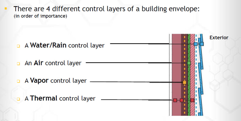
Image courtesy of Georgia-Pacific Gypsum
Four specific barriers are needed in a wall system to control water/rain penetration, air infiltration, vapor transfer, and thermal energy loss (or gain).
An interior finish layer is intended to be just that and is also not considered one of the four main barriers. All of these layers need to work together as a fully coordinated wall assembly system. The four main barriers are discussed further as follows.
Water-Resistive Barriers (WRBs)
This important barrier is intended to do exactly what its name implies – resist bulk water from penetrating into a wall assembly from the exterior side. WRBs are specifically required by the International Building Code (IBC) and the International Residential Code (IRC) for the purpose of protecting the materials and components of a wall assembly from water that may penetrate past the exterior cladding. Without such protection, unwanted water penetration over time can intrude into the assembly, thus producing deterioration, degradation, and even failure, any of which can render a building unsafe or unhealthy for occupancy. To avoid those conditions, a properly tested WRB is typically called for behind the exterior cladding of a wall assembly on the face of the sheathing or similar surface. The wall assembly then needs to be designed to allow the WRB to function as a water control layer by channeling water down its exterior face to drain harmlessly away to the exterior. In so doing, it reduces or eliminates potential water and moisture problems inside a wall assembly, particularly in cavity wall framed construction.
It is worth noting that in the codes, building felt is the only specific product listed as a WRB. Building felt is no longer commonly used, however, because it is difficult to apply to walls and can be time-consuming. Fortunately, other materials are acceptable under the code if they can be tested to demonstrate water-resistive capabilities comparable to or better than building felt. The Sealant Waterproofing & Restoration Institute is a good source for more detailed information on WRBs.
Continuous Air Barriers (AB)
This barrier has received a lot of attention in recent years since unwanted air infiltration has been seen as both a significant drain on energy performance and a means to transfer unwanted airborne moisture into buildings. In particular, the International Energy Conservation Code (IECC) now has very specific, mandatory requirements for providing continuous air barriers in building envelopes aimed at restricting or preventing the passage of air in order to assure minimum levels of code-required energy performance. The code leaves it to the architect to determine the best location of the AB, whether on an interior or exterior side of a construction assembly, but does indicate that it needs to follow the same line as the building thermal barrier. Its purpose is to essentially “wrap” the building shell to prevent air from passing from the outside to the inside due to wind, building “stack effects”, or mechanical ventilation pressure differences. To achieve this in exterior walls, the AB is most typically located behind wall cladding on the face of sheathing or similar surface, just like a WRB.
It is worth noting that the IECC identifies 16 common building materials that qualify as an acceptable air barrier, including such things as ½ inch or thicker gypsum board, plywood, OSB, roof membranes, concrete, masonry, and metals, among others. This makes sense since it is hard to imagine air blowing directly through any of these materials. The IECC clarifies the requirement and also allows for other materials to be used as an approved air barrier if it can show by testing per ASTM E2178 that it achieves an air penetration rate of no more than 0.004 cfm/ft2 (four thousandths of a cubic feet per minute per square foot of material) when tested at a pressure difference of 75 Pascals. This is fairly good news for most materials, but there is an additional requirement that cannot be overlooked, namely, the seams, joints, openings, or penetrations of those materials must also resist air. Under the IECC, in order to qualify as an acceptable continuous air barrier, the entire assembly of materials and products must restrict air penetration. In this case, the complete assembly must be tested, not just the sheathing or similar product, and demonstrate an air penetration rate of no more than 0.04 cfm/ft2 (four hundredths of a cubic feet per minute per square foot of material), also when tested at a pressure difference of 75 Pascals. While the requirement for the assembly is less stringent than for the materials, it is nonetheless a dramatic, measurable improvement over previous versions of the IECC, which did not fully address an AB. As a result, it means that much more attention needs to be paid to the continuity of the AB and that all seams, joints, penetrations, and openings must be carefully detailed and properly sealed. The Air Barrier Association of America (ABAA) is a good resource for more information on air barriers.
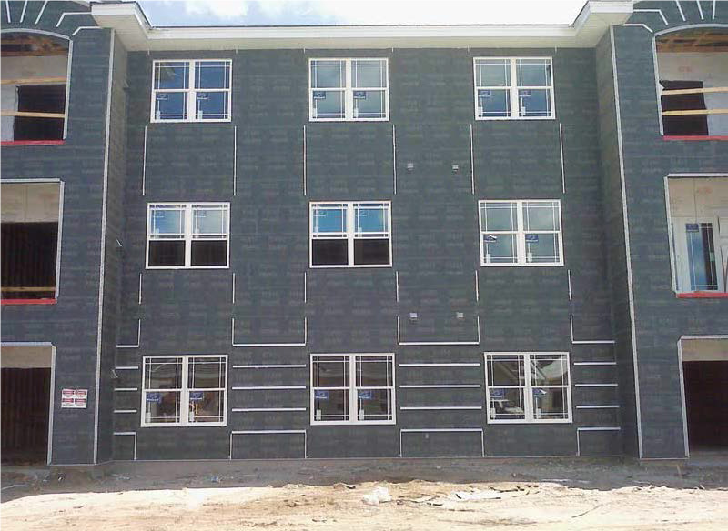
Photo courtesy of Georgia-Pacific Gypsum
Air barriers and water barriers can take many different forms, but are typically located on the face of exterior wall sheathing in commercial buildings.
Vapor Retarders
While WRBs address bulk water, and ABs address airborne moisture from one side of an assembly, a third barrier addresses a concern for vapor penetration from the other side of the construction assembly. The IBC and IRC require the use of vapor retarders to protect the building construction. Most commonly, a vapor retarder is required in colder climates and should be installed on the interior face of an exterior wall, roof, or floor assembly. The intent is to prevent warm, moist air from penetrating into the assembly and condensing to form water that can become trapped and cause damage. The determination of whether or not a vapor retarder is required is based on the location of the building within any of the eight code-defined climate zones. Then, depending on the location, one of three types of vapor retarders may be dictated. A Type I retarder provides virtually no permeability for vapor, while a Type II allows some permeability. A Type III vapor retarder slows the passage of vapor, or diffusion, but allows more permeability than either Type I or Type II. In this case, it is presumed that any vapor that enters will also find its way to exit or drain back out.
Thermal Barriers
Restricting the transfer of heat through a building envelope (i.e., from inside to outside during heating season or from outside to inside during cooling season) is critical to good energy performance in a building. Therefore, the IECC has always required a continuous thermal barrier to control heat energy flow and reduce energy usage in buildings. The level of performance of this barrier is expressed in tested R-values for insulation products or based on U-factor analysis of an entire assembly. In practice, that means that insulation is used to form the thermal barrier and can be placed between studs and framing or installed continuously either on the inside or outside face of an assembly. The specific assembly and the materials used can be quite varied and are the purview of the architect to determine based on the needs of a particular building. Whatever the design, however, thermal performance must be detailed and demonstrated to show code compliance.
Barrier Products
As with most design and construction systems, there are choices available in the marketplace to achieve any or all of these four barriers. Recognizing the need to provide these functions, manufacturers traditionally have provided a range of products to create just one of these four specific barriers. That means a well-designed wall assembly requires multiple products installed, which translates into multiple laborers performing multiple tasks for a finished wall. It also means that it is up to the architect or other professional to ensure that the multiple products are compatible with one another so they will perform as intended and hold up over the life of the building.
In light of the shortcomings of solutions that require multiple products, some gypsum manufacturers have developed and now offer the latest innovation in barrier technology, namely, integrating both a WRB and AB directly into a fiberglass mat-faced gypsum sheathing. This allows one engineered product to provide multiple control layers with a single material installation. As such, it can achieve higher performance in the field, including high performance in blower door tests. Integrated gypsum sheathing products also allow a simpler, more streamlined installation process and with less labor required. The simplicity of the system helps ensure quality and control costs.
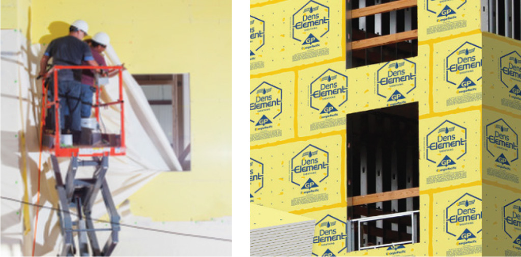
Photos courtesy of Georgia-Pacific Gypsum
Different products for installing air and water barriers require different installation methods, such as building wrap compared to integrated gypsum sheathing.
With integrated gypsum board sheathing, the AB and WRB are installed in factory-controlled conditions with high-quality standards. Once the sheathing is installed on the building, the seams and fasteners are sealed, allowing it to serve as a continuous air barrier plus a continuous water-resistive barrier and drainage plane. It is important to note that this type of product is a high-performance gypsum sheathing, meaning that it still provides all of the needed attributes of exterior wall sheathing (e.g., structural integrity, fire resistance, etc.), just enhanced to also provide WRB and AB capabilities.
Barrier Continuity
As already noted, materials like integrated gypsum sheathing and others can be tested and shown to meet barrier requirements. However, there is also a need to ensure continuity across the joints, seams, and other edges of those materials. Similarly, special attention needs to be paid to the places where barriers surround an opening or cross over different construction conditions, or different materials.
An accepted method of helping to ensure the building enclosure performs as intended is commissioning of a building envelope. This is similar to commissioning mechanical and electrical systems to assure their proper performance. One of the best tools to begin the envelope commissioning process occurs during design, using a building cross-section or floor plans, and doing what is often referred to as “the pencil test”. Simply put that means taking a pencil and starting in a selected corner of the drawing then tracing the line of each of the four barriers moving upward along the walls, horizontally across any projections or the roof, then back down to the footing on the other side, and horizontally across the lowest floor back to the point of beginning. Anywhere the pencil encounters anything other than a smooth, continuous surface, it is circled to identify potential areas of barrier interruptions or transitions. This includes things like a wall penetration, fenestration openings, material offsets, or changes in materials.
Each circled area identified in the pencil test now represents an architectural detail that is required in order to communicate how the barriers connect and remain continuous across those circled conditions. Those details, in each area identified, must be thought through and shown in the final construction drawings so that all barriers can indeed be constructed as continuous. It is no longer enough or appropriate to simply write the word “continuous” in a note identifying the barrier – it must be accompanied by an architectural detail.

Photo and image courtesy of Georgia-Pacific Gypsum
True continuity of barriers in a building starts during the design phase, using the “pencil test” to identify locations that require detailing.
Of course, those architectural details need to be straightforward so that the barriers can be readily installed in the field using common construction practices. This helps allow for proper installation to achieve the intended continuity and high performance. It is worth pointing out that using integrated sheathing simplifies the architectural details and hence simplifies the construction to achieve continuous air and water-resistive barriers.
As an extra safeguard and to avoid any unforeseen problems, the focus of the design of the details should include a strategy for drying out an assembly in the event that moisture does penetrate somehow. That means allowing for drainage of any moisture or bulk water in all assemblies, as is commonly done with flashing and weep holes, etc. In some cases, it may also mean allowing for ventilation, as in a rain-screen or other type of back-drained assembly. Some building scientists point out that attention to drying and drainage helps prevent on the order of 95% of typical water and moisture problems, no matter what you do to the rest of the building.
Barrier Continuity Approaches
With all of the above in mind, let’s look at how some different wall assembly options achieve barrier continuity.
Building Wraps: Conventional exterior framing and sheathing assemblies often use a common field-installed building wrap sealed with a typical tape-style flashing. The building wrap is available on long rolls and is usually installed by unrolling it and fastening it to the sheathing with a pneumatic cap stapler to hold it in place. Of course, penetrations are made in the wrap at each staple. Then, all of the wrap seams are overlapped and sealed with 2 ½-inch flashing tape to create continuity, although it does take some time and expertise to achieve good results. Around door and window openings, 6-inch self-adhered flashing needs to be applied after the building wrap is cut and/or folded to accommodate the openings. All of this amounts to some considerable effort, with quality control entirely dependent on the skills of the field installers. It is also dependent on the ability of the building wrap and installation to hold up while being exposed to the weather until the final cladding is installed.
As products, building wraps have the advantages of working well as either a WRB or AB, they are well-known, fairly cost-effective, and straightforward to install in almost any weather condition. They are also usually vapor permeable, meaning that any vapor trapped within the assembly can escape back out through them. Their disadvantages lie not in the product, then, but in their installation during construction. All require fasteners or staples to hold them in place, which causes holes that compromise their ability to act as a WRB. They are also difficult to seal in order to create a truly continuous AB. And as anyone who has visited a construction site where building wraps are left exposed can attest, they are prone to fluttering in the wind, which can create larger holes, rips, tears, or failure.
Fluid-Applied Membranes: Assemblies that use untreated exterior sheathing can incorporate a continuous coating of a fluid-applied membrane that is applied over the entire surface. In this case, the membrane can be spray applied to achieve a uniform, continuous layer, or it can be roll applied from 20 oz. “sausage” guns with specific attention to seams and fastener heads. Door and window openings all need to be fully flashed with fluid sealant to ensure continuity there. Once again, this fully field-installed application is extremely dependent on the skills and capabilities of the people doing the work.
The multiple capabilities of fluid-applied membranes give them the advantage of potentially acting as a WRB plus an AB when covering over sheathing. They are widely available, seal continuously around rough areas and openings, and have a fairly quick installation time through spraying or rolling. Their disadvantages are found in the field in the form of weather limitations for application, the possible need for a preliminary sealing of joints and fasteners first, plus the control of the application thickness for uniformity and effectiveness. They also require careful review of the manufacturer’s information to be sure that permeability and performance match expectations.
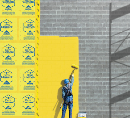
Photo courtesy of Georgia-Pacific Gypsum
Fluid-applied membranes are appropriate for use over a wide range of substrate materials.
Adhered membranes: Installing an adhered membrane over sheathing may provide both WRB plus AB protection in a consistent, manufactured thickness. Since adhesives are used, no fasteners are required, and no joint sealing is needed ahead of time. They have the disadvantages of being more labor-intensive to cut and install the membrane; they usually require a primer first for good adhesion and may be prone to wrinkling or poor adhesion if not installed well. Further, termination mastics and accessories are often needed along with some sequence planning to be sure they are solving moisture problems and not causing them. Adhered membranes also have weather limitations, often create a lot of scrap and waste on site, and the permeability can be impacted by the primer application.
Integrated Sheathing: In contrast with building wrap, fluid-applied systems, and adhered membranes, a simpler installation method is the use of integrated gypsum board sheathing. This product fuses or marries a gypsum core to the fiberglass mat surface in a way that creates a single, monolithic WRB and AB product. More specifically, it integrates the gypsum core and fiberglass mat to form a hydrophobic, monolithic surface that blocks bulk water but allows vapor to pass through. The ability of integrated fiberglass mat sheathing to provide a fire and weather-resistant substrate for multiple types of exterior cladding has made it a popular and cost-effective choice for many commercial buildings.
Incorporating integrated sheathing with a WRB and AB surface means only the joints of the sheathing panels and any penetrations need to be addressed for barrier continuity, not the entire surface. This is achieved through the selective use of sealants and liquid flashing to address joints, penetrations, seams, corners, and other irregular conditions. That involves much less work and time when compared to building wraps, self-adhered sheet goods, or fluid-applied systems. That also means there is less risk of error or flaws in the system. Of course, those flashing products need to be compatible with the barrier materials that they are sealing, so using manufacturer-recommended liquid products is important.

Photos courtesy of Georgia-Pacific Gypsum
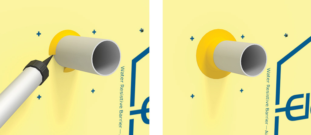
Sealing the seams and corners of integrated sheathing involves the proper use of liquid flashing that is applied and then spread smoothly.
The process for sealing along joints between integrated sheathing panels involves the following:
- Apply liquid flashing over the integrated sheathing joint in a zig-zag or ribbon pattern dispensed from a tube-type container.
- Limit the application since only a minimum 1-inch wide covering is needed on each side of the joints.
- With a 4- or 6-inch straight edge knife or trowel, spread evenly over the sheathing joint.
- Apply at a rate to achieve a minimum wet mil thickness of 16 mils over the entire joint area, leaving no exposed sheathing.
The typical process for assuring continuity at vertical corners using an integrated sheathing system is similar:
- Prime any exposed gypsum edges of the sheathing with a recommended primer.
- Apply liquid flashing over the inside and/or outside corner in a zig-zag or ribbon pattern dispensed from a tube-type container. In this case, cover a minimum of 2 inches on both sides of the corner.
- Using a 4-inch or 6-inch straight edge knife or trowel, spread the liquid flashing evenly over the sheathing corner.
- Apply at a rate to achieve a minimum wet mil thickness of 16 mils over the corner area.
Fasteners are addressed in a very simple manner. All fasteners should be spot covered with liquid flashing and wiped down with a straight edge tool, leaving a minimum wet mil thickness of 16 mils over the entire fastener.
Transitions Between Foundations and Walls
We have covered the basic issues and choices for addressing continuity of barriers within specific materials, including simplified processes for continuity with integrated sheathing. In addition, there are also places where wall sheathing typically needs to make a transition with some other parts of the building construction. The first such area is across transitions between foundations and exterior walls. Foundation walls and sheathed, framed exterior walls are frequently aligned with each other in the same building plane. However, the seam or transition line between the exterior wall and the foundation construction is very often a weak point in air and water barrier continuity that needs to be addressed.
Some manner of rigid or flexible flashing is almost always needed at the foundation and wall joint so that water, which can find its way down the face of the sheathing, has a place to safely exit out and away from the wall assembly. This is common in masonry veneer wall assemblies, where the use of proper flashing, weep holes, and other means is important for good drainage and drying in the event that bulk water or condensation accumulates behind the masonry cladding. Note that it is equally important to prevent air infiltration along this transition seam between the wall and foundation so that the air barrier remains continuous across both of these construction assemblies.
Using integrated sheathing for the exterior wall means that the sheathing surface provides a continuous air and water barrier right up to the bottom edge of the sheathing. By also providing liquid flashing over and behind the metal flashing on the wall, the joint is sealed along the flashing line, assuring that water and air do not penetrate along this flashing line. A similar application of liquid flashing directly across the line of the seam or transition should also be applied. The foundation construction assembly should then be treated with a separate, appropriate coating so it meets the criteria for water and air resistance. In this way, all water and air barriers are run up to each other, overlapped with liquid flashing, and are indeed continuous.

Image and photo courtesy of Georgia-Pacific Gypsum
Transitioning from a framed wall system to the foundation is a prime example of the reason for good architectural detailing, so barriers remain truly continuous.
When creating architectural details for this foundation-to-wall transition in brick veneer walls over integrated sheathing, liquid flashing can be applied in strategic places to work with traditional flashing and weep hole techniques for masonry construction. This provides continuity between the integrated sheathing and the foundation by sealing above and below the flashing without interfering with other aspects of the masonry veneer design. If the building exterior is being clad with stucco, similar architectural details can be created that use liquid flashing in selected locations under and over flashing edges. This reinforces the barrier continuity along flashing and other dissimilar substrate materials and ties the barriers along the wall directly to the barriers along the foundation.
Transitions Between Disparate Wall Materials
Exterior walls, all by themselves, can have transitions across disparate materials or conditions. This can include dissimilar wall materials abutting each other, openings in the wall needed for fenestration, or penetrations through the wall for piping, electrical lines, or other conditions.
Dissimilar Materials
Dissimilar or differing adjacent building materials can create their own challenges. Continuing air barriers and water-resistant barriers across such differing materials requires a way to bridge across the two materials to assure true continuity of the barriers. This is one of those critically important places where it is not enough to simply add a note to the drawings; rather, an architectural detail is needed to address the transition. Then, during construction, the actual work needs to be done properly to ensure high-performance results without air or water leakage.
The process of bridging this transition is simplified when one of those dissimilar materials is integrated sheathing, since liquid flashings can be used to accomplish this objective and cover the edges between the integrated sheathing and other materials. The gypsum-based sheathing can readily be cut and fit to conform to different shapes, and the flashing can be selected to be compatible with a range of materials. Of course, there is a need to assure compatibility with those other materials, too, so manufacturers’ recommendations should be sought here. For long-term effectiveness, the surfaces need to be cleaned, primed, or otherwise prepared properly to receive liquid flashings.
Here is the typical process recommended to follow in the case of a transition between integrated sheathing and another dissimilar wall material:
- If the gap between materials is over 1/8-inch, fill the gap between the integrated sheathing and adjacent materials with a backer rod.
- If necessary, prime the adjacent material with primer per the material manufacturer’s recommendations.
- Apply liquid flashing over the integrated sheathing and the adjacent material in a zigzag or ribbon pattern dispensed from a tube-type container. Assure that the flashing is applied with a minimum of 2 inches on each side of the joint across both material surfaces.
- With a 4-inch or 6-inch straight edge knife or trowel, spread the liquid flashing over the material transition joint.
- For a measure of safety, apply the liquid flashing at a rate to achieve a minimum wet mil thickness of 16 mils, notably thicker than joints simply between integrated sheathing panels.

Photos courtesy of Georgia-Pacific Gypsum
Sealing along the edges of dissimilar materials may require some extra steps or detailing to achieve full continuity.
Wall Openings
The second disparate wall condition to address is transitions around fenestration openings (windows, doors, glazing, etc.) in walls. Not only are openings like this an interruption of all four of the barriers simply by virtue of their presence, but they also constitute one of the most likely places for water and air leaks to occur. In virtually every building, windows, particularly if they are recessed back into the wall assembly, should be considered an area that will require architectural details specifically showing how the air and water barrier on the exterior wraps the opening and connects to the vapor retarder or air barrier on the inner surface of the wall. Not addressing these conditions can cause unwanted air leakage around installed windows or other fenestration. They can also be responsible for water infiltration and leaks into the wall assembly that may go undetected until significant damage is done.
In order to address continuity around fenestration openings, integrated sheathing can again simplify things. Similar to joints, corners, and fasteners, the process of using liquid flashing with integrated sheathing is relatively easy and quick to install as follows:
- Prime any exposed edges of the gypsum integrated sheathing with primer.
- Apply a bead of liquid flashing into the entire depth of the inside corners of the opening, dispensed from a tube-type container.
- Spread liquid flashing with a trowel around the entire opening onto the sills, the jambs, and the headers
- The liquid flashing should extend to the seal located at the interior edge of the window frame so the interior and exterior barriers can be connected and thus form continuous layers.
- Apply liquid flashing over the sheathing adjacent to the opening sill, jamb, and header in a zigzag or ribbon pattern dispensed from a tube-type container. Cover a minimum of 2 inches of the sheathing surface adjacent to the opening.
- With a 4-inch or 6-inch straight edge knife or trowel, spread liquid flashing over the entire width of the sill, jamb, header and integrated sheathing surface adjacent to the opening.
- For best results, apply at a rate to achieve a minimum wet mil thickness of 16 mils over the opening area, leaving no exposed sheathing.

Photos courtesy of Georgia-Pacific Gypsum
Sealing and flashing around wall openings, such as windows and doors, is critically important since these are the areas most prone to breaching of the barriers.
Wall Penetrations
The third area where disparate wall transitions occur is penetrations through exterior walls, such as piping, sleeves, wiring, etc. Here is the rather simple process to follow when integrated sheathing is used in the wall assembly.
- Mechanically secure all penetrations so they don’t move within the opening.
- If the gap between materials is over 1/8-inch, install a backer rod between the penetrating item and the integrated sheathing to form a back dam regardless of size of penetration or opening.
- Apply a thick bead of liquid flashing from a tube-type container around the penetration.
- Use a flexible spatula to spread the liquid flashing around the penetration
- Feather the liquid flashing and keep it continuous to completely seal the joint around the penetration.
Photos courtesy of Georgia-Pacific Gypsum
Wall penetrations from mechanical or electrical piping, conduit, etc., all need attention to assure that water and air barriers are continuous.
We have seen the typical conditions in an exterior wall where disparate material transitions can occur. In comparison with other Water Resistive Barrier and Air Barrier options, integrated sheathing combined with the use of liquid flashing in specific locations can be used as a much easier, quicker, and more economical approach than using alternative systems.
Transitions Between Walls and Roofs
With foundations and walls properly addressed, the final area to focus on is making barrier transitions between wall and roof systems. Commercial buildings with low-slope roofing systems often use a parapet wall that continues up past the level of the roof. This presents some concerns and challenges in order to ensure that the air and water barriers are continuous from the wall assembly to the roofing assembly.
Roof parapets are a common part of many building designs because they serve multiple purposes. In many cases, they contribute to the aesthetic design of a building since they can add visual interest to a façade by improving the proportions or appearance of the building. Or they can simply be used to hide rooftop equipment from view at the ground level. From a roofing practical standpoint, they can serve as the termination point for roof edges and flashings to assure a watertight roofing installation. They can also provide a diversion to air or wind that blows along the roof edge, thus helping with resistance to wind uplift of the roofing. Parapets may also promote fire resistance by helping to contain a fire on the roof of the building or keeping fire from spreading that may have started in an adjacent building.
Despite all of these various uses and purposes, there are some design and performance issues with parapets. In particular, they have often been found to be a high-risk moisture management detail that needs special attention to be sure that the transition between roof and wall assemblies isn’t inadvertently compromised in terms of moisture intrusion. The same issues arise in terms of keeping the air barrier continuous at parapets.
The most difficult question is where does a parapet wall begin and end in relation to a wall and roofing system? Technically, the parapet portion extends up above the line of the thermal envelope in the wall, so insulation is often not installed in them. With or without insulation, the water and air barrier aspects of these parapet walls are critically important since they can still be sources of failures and potential damage.
Consistent with the importance of continuity of barriers elsewhere, the key to successful parapet design is to identify how the wall and roof barriers continue and connect.
Moisture and water management must be addressed as the first priority in the wall assembly, the roofing, and any special details such as parapet coping. But it is equally important to address the continuity of WRB and AB, which must be continuous per the building codes over the entire exterior thermal envelope, which includes parapet walls. As such, the “pencil test” and architectural details need to address the continuity of the WRB and AB extending up the exterior wall, continuing across and over the top of the parapet, and then back down to the roof.
Photo courtesy of Georgia-Pacific Gypsum
Roof parapets are places to ensure that the water and air barriers extend up the wall, across the top of the parapet, and then connect with the roofing systems and barriers.
When detailing parapets, the use of an integrated sheathing system is a straightforward way to solve parapet issues while again helping to simplify the design and installation. Using glass-mat integrated gypsum panels that continue up the wall and extend over and across the parapet wall is the first step. Then, extending a similar integrated gypsum panel used as a roof cover board, which extends up the back of the parapet, is an industry best practice. At the joint between these two types of integrated sheathing, liquid flashing can be used in the manner shown already to assure the full continuity of the WRB and the AB.
It’s important to note that in some cases, the roofing is certified based on the sheathing or roof board product used for the roofing assembly. It is important, therefore, to recognize that some gypsum sheathing is certified for roofing, others for walls. Hence, the best choice for a parapet may be to continue a gypsum roofing board up along the vertical parapet wall to maintain the roofing integrity and ratings. Liquid flashing can still be used along joints for continuity of water-resistive and air barriers.
Conclusion
There are different conditions and different products available for ensuring the continuity of barriers in wall construction and the transition of those barriers to other materials and conditions. Architects and others can incorporate the information presented in this course into current and ongoing building design work. First, it should be clear that coordination and proper use of architectural details are needed so that wall assembly products work together. Those details should consider best design practices as well as the manufacturer’s recommendations,
The second thing to remember is that controlling air and water barriers in exterior walls does not need to be done only by using separate products installed in separate layers Instead, some layers and barriers can be simultaneously provided through the use of integrated products such as integrated gypsum sheathing which has been shown to be a superior, high-performance solution. Specifically, it has been demonstrated to provide:
Better control of the air and water barriers since they are embedded in the product during manufacture
Improved continuity at transition areas through the limited but specific use of compatible liquid flashing products.
Reduced risk of on-site mistakes and performance compromise since the bulk of the quality control is done in the factory, with only joints, openings, and transitions needing to be addressed in the field.
Overall, integrated sheathing has been shown to save installation time, reduce labor hours, and control project expenses. All of this is accomplished while providing better, more predictable performance compared to other alternatives for water-resistive barriers and air barriers.