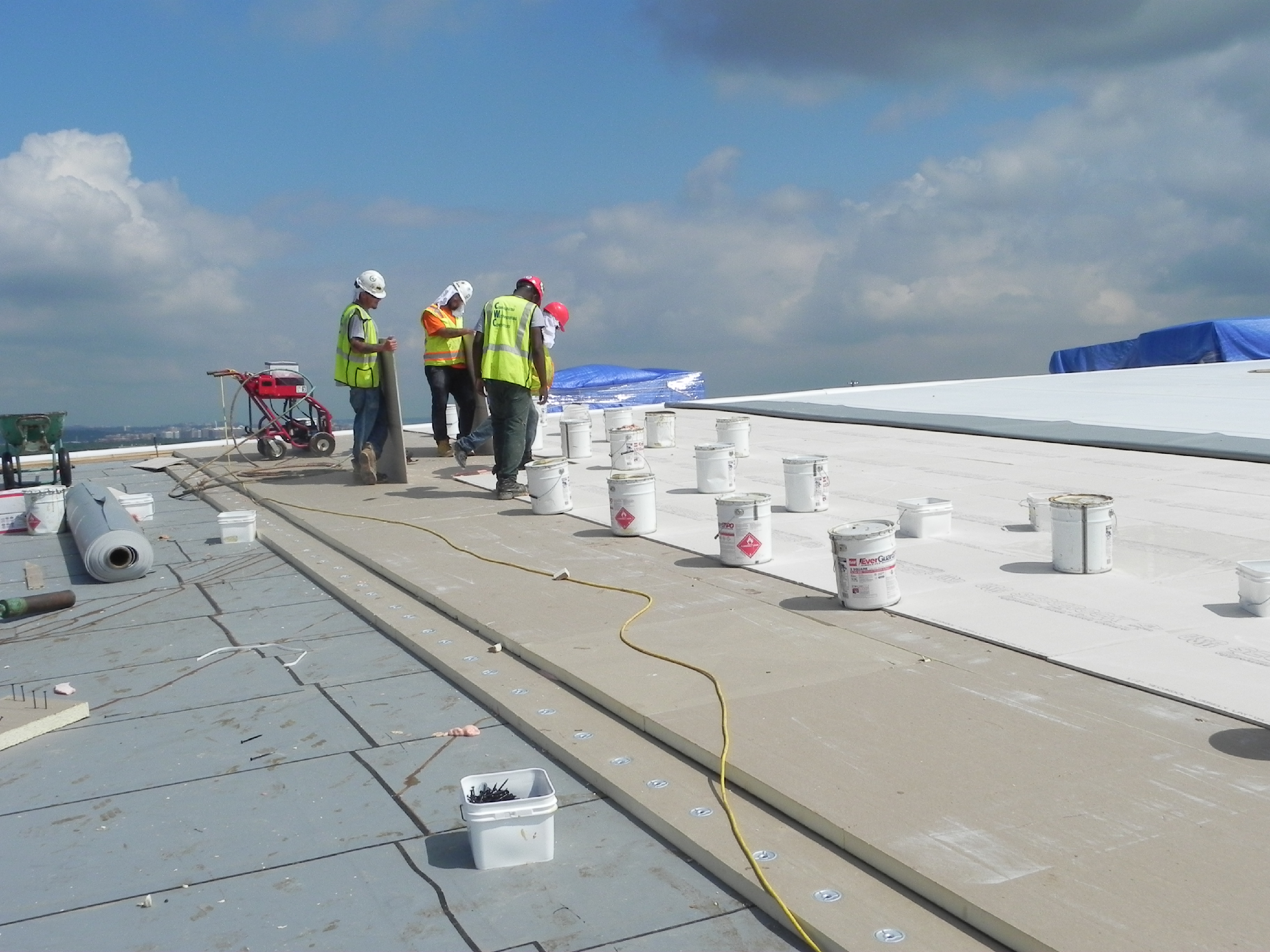
Photo courtesy of GAF
Photo 1. Let’s address a common area of confusion: "What is the difference between an air barrier and a vapor retarder?" While an air barrier stops air leakage, a vapor retarder reduces moisture diffusion to reduce the risk of condensation forming in the roof assembly. But can an air barrier be a vapor retarder?
Unravelling Codes and Performance
The building's enclosure or envelope is made up of multiple layers of materials aimed at achieving the goal of keeping the outside elements out and the inside conditioned space in. In order to perform as intended, the enclosure must be effective at stopping the uncontrolled movement of water, air, heat, and moisture vapor. This is accomplished through the use of a control layer targeted at each of these elements.
On both roofs and walls, these layers must include an air barrier and sometimes a dedicated vapor retarder. When designed and installed properly, these materials can help building owners save energy, improve indoor air quality and maintain occupant comfort.
Defining Air Barrier Compliance within the IECC
The minimum requirements for the building enclosure can be found in the International Code Council’s International Building Code® (IBC) and the International Energy Conservation Code® (IECC). The IECC references The American Society of Heating, Refrigerating and Air-Conditioning Engineers® (ASHRAE) Standard 90.1 for many criteria. The requirements within these codes and standards can be mandated prescriptively, as a performance threshold, or by reference through specific key standards. Performance-driven standards are important because they do not attempt to regulate by providing exhaustive lists and itemized component requirements, as in a prescriptive method. Performance requirements establish the design benchmark and then provide a methodology to demonstrate compliance with the benchmark1.
Designers should always consult their local code to determine whether a dedicated air barrier is needed for a particular project. Under the widely adopted IECC 2018 and ASHRAE 90.1 2016, a building enclosure is required to contain a continuous air barrier for all new construction except in climate zone 2b. ASHRAE 90.1 defines a Continuous Air Barrier as a "combination of interconnected materials, assemblies, and sealed joints and components which together minimize air leakage into or out of the building envelope." This definition provides a good, yet simplified description of what is needed to have a building enclosure with minimized air leakage (IECC C402.5 & 90.1 5.4.3.1).
Materials and assemblies used as a part of the building's continuous air barrier are typically tested by the manufacturers of those materials to comply with industry standards and to perform when installed in accordance with the manufacturer's instructions for that application. Air barrier materials are evaluated under ASTM E2178, Standard Test Method for Determining Air Leakage Rate and Calculation of Air Permeance of Building Materials. This test measures the air permeance of flexible sheet or rigid panel-type materials. The results can be used in determining suitability of a material as a component of an air barrier system. The building codes require measurement at air pressure differential of 0.3 inches w.g. (75 Pa) and an air permeance of less than 0.004 cfm/ft2 (0.02 L/s-m2) to qualify as an air barrier material. However, testing of air barrier materials, while necessary, is not sufficient to ensure performance in application.
The ultimate goal of airtightness is whole-building performance. To help accomplish that goal, the energy code specifies aspects of air barrier design (IECC C103.2 & ASHRAE 90.1 5.4.3.1.1) and installation (IECC C402.5.1.1 & ASHRAE 90.1 5.4.3.1.2) for continuity across joints, penetrations, and assemblies.
To verify that these requirements are met, the design professional can select assembly testing and/or whole building performance testing. Assemblies may be tested according to ASTM E2357, E1677, D8052, or E283. For commercial wall air barrier systems, the most common test method is ASTM E2357; ASTM E1677 is most common for residential and low-rise construction; D 8052 is a roof system air barrier test method. ASTM E283 is a test method utilized in each of the other three, as unlike air barrier system tests it does not define the assembly parameters of what is tested. These test methods determine air leakage rates of air barrier assemblies and are intended to simulate in the lab the performance of various air barrier materials and accessories when combined into an assembly. Generally, a result of 0.04 cfm/ft2 (0.2 L/s-m2) or less at 0.3 inches w.g. (75 Pa) demonstrates acceptable performance per industry and code standards. However, the results of assembly tests are intended to be used for comparison purposes and do not necessarily represent the installed field performance of the air barrier assembly when installed as part of a whole building air barrier system.
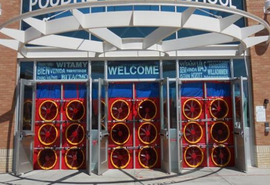
Photo courtesy of Siplast
Photo 2. Image of ASTM E3158 whole building airtightness test being performed.
To truly evaluate the real performance of an air barrier system, whole building airtightness can be tested according to ASTM E3158, E779, or E1827. These tests provide an actual measurement of building enclosure performance and are the only assessment of installed performance, including materials, assemblies, and complete systems. Commonly referred to as blower door testing, fan-induced pressure differentials are produced across the building enclosure, allowing for the measurement of the air-leakage rate of the constructed building enclosure. The maximum air leakage rate for whole building airtightness testing can range from 0.15 to 0.40 cfm/ft2 at 0.3 inches w.g. (75 Pa) depending on the jurisdiction and building code. The 2024 IECC sets the standard for whole building airtightness at 0.35 cfm/ft2 (1.8 L/s-m2) at 0.3 inches w.g. (75 Pa) (Section 402.6.2).
The IECC and other building codes continue to incorporate stricter air leakage standards, leading to more mandatory blower door testing for commercial buildings. Blower door testing is also increasingly part of the building commissioning process, which is a process aimed to ensure that the building is performing as designed.
The Responsibility to Meet Codes
The goal of creating a durable and efficient building is to first establish performance expectations and then design an enclosure that performs as intended and that continues to perform through the project lifecycle. Beginning under 2015 IECC, a continuous air barrier is required by code for most jurisdictions. The air barrier can be located on the inside, outside, or within the assemblies of the building enclosure, or any combination thereof (2024 IECC Section C402.6.1). It is the responsibility of the registered design professional to clearly identify all air barrier components of the enclosure and provide air barrier and air sealing details at joints, penetrations, transitions and other interfaces (IECC 2024 C105.2.5). In some jurisdictions, they may also need to determine the need for an air barrier.
IECC 2024 Sections 402.6.1.1 and 402.6.1.2 call out the detailing requirements to ensure that the air barrier is continuous during the design phase and during construction.
Vapor Retarders within the IBC
Vapor retarders are increasingly being specified for inclusion in low slope roof assemblies. A vapor retarder is a material that, depending on its exact specification and installation, slows down or eliminates the transmission of moisture vapor from one side to the other by way of diffusion through the material. Vapor retarders can help manage migration of moisture vapor from warm, humid interiors up through a roof assembly to the underside of the roof membrane. They can also limit the amount of moisture migrating from a concrete deck up into the roof assembly.
IBC 1404.3 defines vapor retarder materials and classes for wall assemblies. There are different classes of vapor retarding material (I, II, and III) and each class of material allows differing amounts of moisture vapor to pass through via diffusion. Determination of vapor permeance is by way of testing according to ASTM E96 Method A (desiccant method) and/or B (wet cup method) at a 50% humidity differential. Class 1 is a material assessed at 0.1 perm or less and can be regarded as impermeable or vapor closed. A Class 2 is semi-impermeable, with a rating between 0.1 to 1.0 perm. Class 3 is semi-permeable, with a rating between 1.0 and 10.0 perm. A material with a permeance greater than 10 perms is considered vapor open, meaning that moisture will flow through this material most readily. It is up to the designer to determine the class of vapor retarder required for a wall design. It is important to understand that all materials, not just those identified as vapor retarders, have a level of vapor permeance that can have an impact on the building enclosure performance.
It is important to recognize that vapor retarders are not required by code in the same way that air barriers are. Building codes do not require the installation of a vapor retarder in roof or wall assemblies. A determination as to whether to include a vapor retarder must be made by the design professional. This determination must be based on the building enclosure assemblies, interior conditions, climate zone and risk tolerance of the building owner.
Building Science: Understanding the Rules of The Performance Game
Having a compliant building means meeting code. Code books assign a definitive role to the building enclosure: separating the interior environment from the exterior environment. Why is this so important? Building occupants expect a level of comfort, including being dry, having thermal comfort and good indoor air quality.
Control Layers
The main control layers of a building enclosure consist of water, thermal, vapor, and air control. The roof membrane and thermal insulation play a pivotal role in water and thermal control on the roof. The cladding and insulation play a similar role on the wall. However, the use of air barriers and vapor retarders also has import for the roofs and walls and can be a source of confusion, particularly for high performance and energy efficient roofs. The order and sequencing of these layers is strongly influenced by the building conditions such as the interior climate and exterior climate zone, as well as how transitions at interfaces such as the roof-to-wall will be detailed. This means the location of each of the control layers within the roof assembly impacts how the roof is tied into the wall and the various control layers within the wall assembly. This is particularly true of air barriers and vapor retarders, as well as the water control layer.
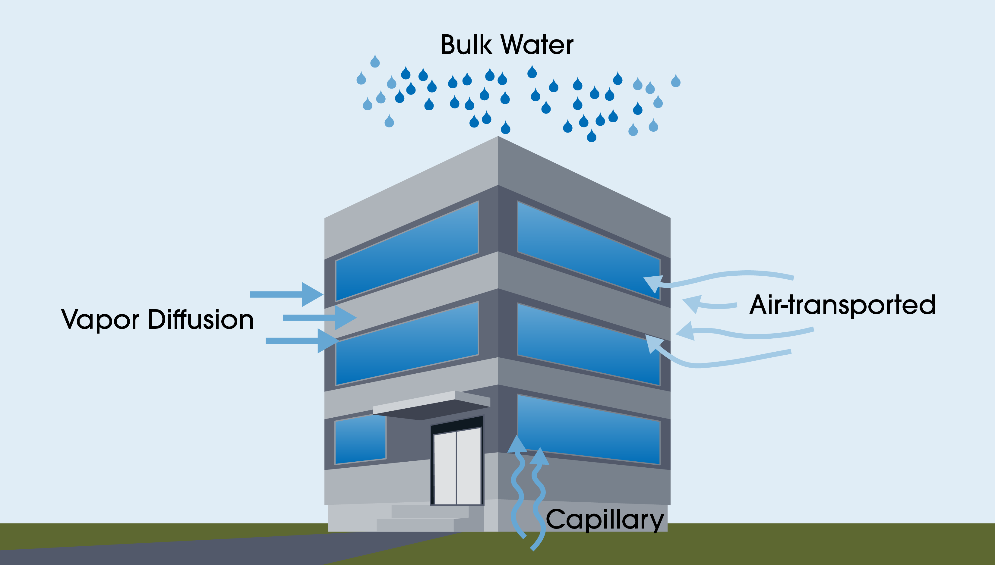
Figure courtesy of GAF | Siplast Building & Roofing Science
Figure 3. The Struggle With Water - The many ways that moisture can enter a building.
Keeping moisture out of a building is difficult. Moisture comes in many forms and can take many paths into a building. Building designers need to account for bulk water, capillary water, air-transported moisture, and water vapor, and must defend against each of these in different ways. The impacts from moisture intrusion are many. For example, leaks from the roof can cause costly damage and repairs to building interiors, but they also can deteriorate the roof assembly itself and lessen its performance. The same is true in walls. Moisture can reduce R-values in the insulation, damage interior finishes, and facilitate biological growth. Additionally, poorly controlled water ingress affects indoor air quality as mold growth in the building enclosure assemblies will find its way into the interior airspace of the building.
Ways Water Moves
There is one rule that defines how heat, air, and moisture move: the second law of thermodynamics. For building and roofing science, this simply means that hot moves to cold, moist moves to dry, and high pressure moves to low pressure. Heat, moisture, and pressure always equalize whenever possible.
Bulk water, such as rain and snow, is kept out of buildings with roof membranes and wall cladding systems. For the wall of an enclosure, achieving a 100 percent successful water barrier is challenging. Walls, with their many penetrations and interfaces, including doors and windows, are difficult to make entirely “waterproof.” As such many wall designs accept the fact that some water ingress might occur and include a drainage path down and then out of the structure by way of a drainage plane or rainscreen assembly. This, however, is not possible for a roof assembly. Roof assemblies must be watertight and designed so that water is not able to enter. Keeping out bulk water consists of watertight detailing that is typical for any roof assembly.
Photo courtesy of GAF
Photo 1. Let’s address a common area of confusion: "What is the difference between an air barrier and a vapor retarder?" While an air barrier stops air leakage, a vapor retarder reduces moisture diffusion to reduce the risk of condensation forming in the roof assembly. But can an air barrier be a vapor retarder?
Unravelling Codes and Performance
The building's enclosure or envelope is made up of multiple layers of materials aimed at achieving the goal of keeping the outside elements out and the inside conditioned space in. In order to perform as intended, the enclosure must be effective at stopping the uncontrolled movement of water, air, heat, and moisture vapor. This is accomplished through the use of a control layer targeted at each of these elements.
On both roofs and walls, these layers must include an air barrier and sometimes a dedicated vapor retarder. When designed and installed properly, these materials can help building owners save energy, improve indoor air quality and maintain occupant comfort.
Defining Air Barrier Compliance within the IECC
The minimum requirements for the building enclosure can be found in the International Code Council’s International Building Code® (IBC) and the International Energy Conservation Code® (IECC). The IECC references The American Society of Heating, Refrigerating and Air-Conditioning Engineers® (ASHRAE) Standard 90.1 for many criteria. The requirements within these codes and standards can be mandated prescriptively, as a performance threshold, or by reference through specific key standards. Performance-driven standards are important because they do not attempt to regulate by providing exhaustive lists and itemized component requirements, as in a prescriptive method. Performance requirements establish the design benchmark and then provide a methodology to demonstrate compliance with the benchmark1.
Designers should always consult their local code to determine whether a dedicated air barrier is needed for a particular project. Under the widely adopted IECC 2018 and ASHRAE 90.1 2016, a building enclosure is required to contain a continuous air barrier for all new construction except in climate zone 2b. ASHRAE 90.1 defines a Continuous Air Barrier as a "combination of interconnected materials, assemblies, and sealed joints and components which together minimize air leakage into or out of the building envelope." This definition provides a good, yet simplified description of what is needed to have a building enclosure with minimized air leakage (IECC C402.5 & 90.1 5.4.3.1).
Materials and assemblies used as a part of the building's continuous air barrier are typically tested by the manufacturers of those materials to comply with industry standards and to perform when installed in accordance with the manufacturer's instructions for that application. Air barrier materials are evaluated under ASTM E2178, Standard Test Method for Determining Air Leakage Rate and Calculation of Air Permeance of Building Materials. This test measures the air permeance of flexible sheet or rigid panel-type materials. The results can be used in determining suitability of a material as a component of an air barrier system. The building codes require measurement at air pressure differential of 0.3 inches w.g. (75 Pa) and an air permeance of less than 0.004 cfm/ft2 (0.02 L/s-m2) to qualify as an air barrier material. However, testing of air barrier materials, while necessary, is not sufficient to ensure performance in application.
The ultimate goal of airtightness is whole-building performance. To help accomplish that goal, the energy code specifies aspects of air barrier design (IECC C103.2 & ASHRAE 90.1 5.4.3.1.1) and installation (IECC C402.5.1.1 & ASHRAE 90.1 5.4.3.1.2) for continuity across joints, penetrations, and assemblies.
To verify that these requirements are met, the design professional can select assembly testing and/or whole building performance testing. Assemblies may be tested according to ASTM E2357, E1677, D8052, or E283. For commercial wall air barrier systems, the most common test method is ASTM E2357; ASTM E1677 is most common for residential and low-rise construction; D 8052 is a roof system air barrier test method. ASTM E283 is a test method utilized in each of the other three, as unlike air barrier system tests it does not define the assembly parameters of what is tested. These test methods determine air leakage rates of air barrier assemblies and are intended to simulate in the lab the performance of various air barrier materials and accessories when combined into an assembly. Generally, a result of 0.04 cfm/ft2 (0.2 L/s-m2) or less at 0.3 inches w.g. (75 Pa) demonstrates acceptable performance per industry and code standards. However, the results of assembly tests are intended to be used for comparison purposes and do not necessarily represent the installed field performance of the air barrier assembly when installed as part of a whole building air barrier system.
Photo courtesy of Siplast
Photo 2. Image of ASTM E3158 whole building airtightness test being performed.
To truly evaluate the real performance of an air barrier system, whole building airtightness can be tested according to ASTM E3158, E779, or E1827. These tests provide an actual measurement of building enclosure performance and are the only assessment of installed performance, including materials, assemblies, and complete systems. Commonly referred to as blower door testing, fan-induced pressure differentials are produced across the building enclosure, allowing for the measurement of the air-leakage rate of the constructed building enclosure. The maximum air leakage rate for whole building airtightness testing can range from 0.15 to 0.40 cfm/ft2 at 0.3 inches w.g. (75 Pa) depending on the jurisdiction and building code. The 2024 IECC sets the standard for whole building airtightness at 0.35 cfm/ft2 (1.8 L/s-m2) at 0.3 inches w.g. (75 Pa) (Section 402.6.2).
The IECC and other building codes continue to incorporate stricter air leakage standards, leading to more mandatory blower door testing for commercial buildings. Blower door testing is also increasingly part of the building commissioning process, which is a process aimed to ensure that the building is performing as designed.
The Responsibility to Meet Codes
The goal of creating a durable and efficient building is to first establish performance expectations and then design an enclosure that performs as intended and that continues to perform through the project lifecycle. Beginning under 2015 IECC, a continuous air barrier is required by code for most jurisdictions. The air barrier can be located on the inside, outside, or within the assemblies of the building enclosure, or any combination thereof (2024 IECC Section C402.6.1). It is the responsibility of the registered design professional to clearly identify all air barrier components of the enclosure and provide air barrier and air sealing details at joints, penetrations, transitions and other interfaces (IECC 2024 C105.2.5). In some jurisdictions, they may also need to determine the need for an air barrier.
IECC 2024 Sections 402.6.1.1 and 402.6.1.2 call out the detailing requirements to ensure that the air barrier is continuous during the design phase and during construction.
Vapor Retarders within the IBC
Vapor retarders are increasingly being specified for inclusion in low slope roof assemblies. A vapor retarder is a material that, depending on its exact specification and installation, slows down or eliminates the transmission of moisture vapor from one side to the other by way of diffusion through the material. Vapor retarders can help manage migration of moisture vapor from warm, humid interiors up through a roof assembly to the underside of the roof membrane. They can also limit the amount of moisture migrating from a concrete deck up into the roof assembly.
IBC 1404.3 defines vapor retarder materials and classes for wall assemblies. There are different classes of vapor retarding material (I, II, and III) and each class of material allows differing amounts of moisture vapor to pass through via diffusion. Determination of vapor permeance is by way of testing according to ASTM E96 Method A (desiccant method) and/or B (wet cup method) at a 50% humidity differential. Class 1 is a material assessed at 0.1 perm or less and can be regarded as impermeable or vapor closed. A Class 2 is semi-impermeable, with a rating between 0.1 to 1.0 perm. Class 3 is semi-permeable, with a rating between 1.0 and 10.0 perm. A material with a permeance greater than 10 perms is considered vapor open, meaning that moisture will flow through this material most readily. It is up to the designer to determine the class of vapor retarder required for a wall design. It is important to understand that all materials, not just those identified as vapor retarders, have a level of vapor permeance that can have an impact on the building enclosure performance.
It is important to recognize that vapor retarders are not required by code in the same way that air barriers are. Building codes do not require the installation of a vapor retarder in roof or wall assemblies. A determination as to whether to include a vapor retarder must be made by the design professional. This determination must be based on the building enclosure assemblies, interior conditions, climate zone and risk tolerance of the building owner.
Building Science: Understanding the Rules of The Performance Game
Having a compliant building means meeting code. Code books assign a definitive role to the building enclosure: separating the interior environment from the exterior environment. Why is this so important? Building occupants expect a level of comfort, including being dry, having thermal comfort and good indoor air quality.
Control Layers
The main control layers of a building enclosure consist of water, thermal, vapor, and air control. The roof membrane and thermal insulation play a pivotal role in water and thermal control on the roof. The cladding and insulation play a similar role on the wall. However, the use of air barriers and vapor retarders also has import for the roofs and walls and can be a source of confusion, particularly for high performance and energy efficient roofs. The order and sequencing of these layers is strongly influenced by the building conditions such as the interior climate and exterior climate zone, as well as how transitions at interfaces such as the roof-to-wall will be detailed. This means the location of each of the control layers within the roof assembly impacts how the roof is tied into the wall and the various control layers within the wall assembly. This is particularly true of air barriers and vapor retarders, as well as the water control layer.
Figure courtesy of GAF | Siplast Building & Roofing Science
Figure 3. The Struggle With Water - The many ways that moisture can enter a building.
Keeping moisture out of a building is difficult. Moisture comes in many forms and can take many paths into a building. Building designers need to account for bulk water, capillary water, air-transported moisture, and water vapor, and must defend against each of these in different ways. The impacts from moisture intrusion are many. For example, leaks from the roof can cause costly damage and repairs to building interiors, but they also can deteriorate the roof assembly itself and lessen its performance. The same is true in walls. Moisture can reduce R-values in the insulation, damage interior finishes, and facilitate biological growth. Additionally, poorly controlled water ingress affects indoor air quality as mold growth in the building enclosure assemblies will find its way into the interior airspace of the building.
Ways Water Moves
There is one rule that defines how heat, air, and moisture move: the second law of thermodynamics. For building and roofing science, this simply means that hot moves to cold, moist moves to dry, and high pressure moves to low pressure. Heat, moisture, and pressure always equalize whenever possible.
Bulk water, such as rain and snow, is kept out of buildings with roof membranes and wall cladding systems. For the wall of an enclosure, achieving a 100 percent successful water barrier is challenging. Walls, with their many penetrations and interfaces, including doors and windows, are difficult to make entirely “waterproof.” As such many wall designs accept the fact that some water ingress might occur and include a drainage path down and then out of the structure by way of a drainage plane or rainscreen assembly. This, however, is not possible for a roof assembly. Roof assemblies must be watertight and designed so that water is not able to enter. Keeping out bulk water consists of watertight detailing that is typical for any roof assembly.
Setting Control Priorities
There is an order of priority for the prevention of water intrusion. Bulk water is most critical, followed by air-transported moisture, and finally, moisture vapor diffusion2. Contrary to popular belief, air-transported moisture is much more critical to prevent than water vapor that enters a building by diffusion. In a warm climate, air transports 10x more water than diffusion, and in a cold climate, air transports 100x more water than diffusion3! These may seem to be large numbers, but the science and measured data supports it.
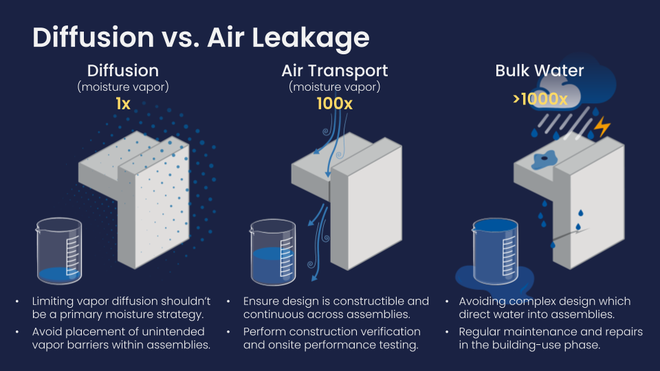
Figure courtesy of GAF
Figure 4. Difference in volume of water movement by way of diffusion, air transport, and bulk water.
Air-transported Moisture
Air-transported moisture, as the name implies, is moisture carried into or out of a building by air that infiltrates or passes through the building enclosure. Airflow is the most effective method of carrying heat and moisture into or out of a building, which is why there are code requirements for air barriers.
There are several ways air conveyance can occur through the building enclosure. Air infiltration occurs when exterior air enters the building interior through gaps in the exterior enclosure. Air exfiltration occurs where interior air exits from the building, also through gaps and inconsistencies in the building exterior. Exfiltration can lead to inefficient HVAC systems, causing the building heating and cooling systems to work harder to maintain interior temperatures, which can ultimately lead to higher energy bills.
Air leakage is defined by the code as both air infiltration and exfiltration. Building science experts identify air leakage as a major impediment to achieving better energy efficiency for the building enclosure. Building owners pay a lot for conditioned air. Air infiltration and exfiltration make up 25% to 40% of total heat loss in a cold climate. Air infiltration and exfiltration make up 10% to 15% of total heat gain in a hot climate. Losing one-third or more of conditioned air has a significant impact on the operational costs of a building. A 2022 publication by the National Institute of Standards and Technology (NIST) found that increasing the airtightness of a building enclosure had an average energy savings of 1.4 kBtu•ft-2, which is 55% higher than that predicted by EnergyPlus for estimated ventilation-related annual energy savings4.
Intrusion refers to the interior air that enters a roof or wall system but does not exit to the exterior. Per the building code, it does not classify as air leakage. However, interior air can be problematic, especially where interior activities cause elevated humidity levels in the air. Where uncontrolled moist air from pools, gyms, or showers enters into the roof assembly, condensation can form if surfaces below the dewpoint are present. Condensation within the roofing assembly is not likely to evaporate. This can lead to wet insulation, roofing components with lowered R-values, water accumulation in the roof deck, and the possibility of biological growth. As such, air intrusion should also be considered and designed for in the same manner as air leakage.
Separating Air Barriers and Vapor Retarders
Dealing effectively with controlling air flow not only allows a building to save energy but also to mitigate air leakage and associated moisture accumulation. Problems caused by air leakage include condensation, increased energy use, and material deterioration. The design professional can prevent these issues with use of effective air barriers and vapor retarders.
Air Barriers 101
Air barriers are systems of materials designed and constructed to control airflow between conditioned and unconditioned space, improving energy efficiency, indoor air quality, and occupant comfort. In 2012, the International Energy Conservation Code (IECC) published some of the first air barrier requirements, stating that a “Continuous air barrier shall be provided throughout the building envelope…” Continuous refers to a barrier with no breaks covering all 6 sides of the building. The purpose of an air barrier is straightforward: first, to minimize the loss of conditioned air from within a building, and second, to reduce energy loss and increase building energy efficiency.
Essentially, the goal of an air barrier is to prevent the loss of conditioned air from the interior to the exterior as well as preventing the uncontrolled introduction of unconditioned air from the exterior to the interior. Just as thermal control needs to take into account thermal bridging, a single material that blocks air is insufficient in and of itself. An effective whole building air barrier system must be an interconnected series of materials and assemblies spanning the entire enclosure. Remember, the obligation for a continuous air barrier is a code requirement.
The IECC highlights three different methods to comply with air barrier requirements: materials, assemblies and whole-building testing. The 2021 and 2024 IECC have adjusted the order in which these apply to a project. First is certification via whole building testing, where the air leakage rate of the completed building can be tested and confirmed to be ≤ 0.35 cfm/ft2 (1.8 L/s · m2)at a pressure differential of 0.3 inches water (75 Pa) per ASTM E3158 or an equivalent method approved by a code official. If this section does not apply to a project based on climate zone or size, the material and assembly requirements must be followed and verified by a code official.
Any material can be used as part of an air barrier assembly so long as the manufacturer can provide a data certificate confirming that the material has an air permeability of no greater than 0.004 cfm/ft2 (0.02 L/s · m2) under a pressure differential of 0.3 inches water gauge (75 Pa) when tested in accordance with ASTM E 2178. Properly installed roof membranes can be used as part of an air barrier system. Several roof membranes are deemed to comply with the code to be suitable for use in an air barrier material (2024 IECC Section C402.6.2.3.1):
- Built-up roofing membrane.
- Modified bituminous roof membrane.
- Single-ply roof membrane.
Note that the IECC states an important caveat – materials shall be deemed to comply, provided that joints are sealed, and materials are installed as air barriers, in accordance with the manufacturer’s instructions. If the roof membranes are to serve as the air barrier within a roof assembly, proper detailing at penetrations and perimeters is vital. This includes the interface with exterior wall assemblies to ensure a continuous air barrier system.
Air barrier assemblies are made up of materials and components (i.e. sealants, tapes, and flashings). They must have an average air leakage not to exceed 0.04 cfm/ft2 (0.2 L/s · m2) under a pressure differential of 0.3 in H2O (1.57 psf) when tested in accordance with ASTM E2357, ASTM E1677, ASTM E1680, or ASTM E283.
The air barrier is, critically, not one material, but instead is an integrated system of many different materials and components. As such, the connection of air barriers at interfaces between transition areas, such as the roof to exterior wall interface, is critical. The materials that are part of the air control layer must stop air movement and interface such that the potential for leaks is minimized. All materials should also be compatible and adhere where required. An air barrier’s effectiveness can be greatly reduced by openings and penetrations, even small ones. These openings can be caused by poor design, poor workmanship, damage by other trades, improper sealing and flashing, mechanical forces, aging, and other forms of degradation.
Vapor Retarders 101
Vapor retarders can be many of the same materials as air barriers: membranes, boards with taped joints, or coatings. All materials in a building enclosure assembly have a vapor permeance and the choice to include a specific vapor control layer should be made in consideration of the local climate, the building use, the rest of the materials within the wall or roof assembly, and the desired degree of assurance that vapor movement is retarded at a specific location.
Vapor retarders are installed to reduce diffusion of moisture vapor through roof materials. Buildings with a higher risk for this type of diffusion are those structures where the building’s interior humidity conditions are expected to be relatively high, such as in natatoriums, or where the building is located in a cold climate. Vapor retarders are designed to have a specific level of moisture vapor permeance to resist moisture vapor diffusion. There are three different classes of vapor retarding material defined for walls by IBC 1404.3. Each class of material allows differing amounts of moisture vapor to pass through via diffusion. The ability to slow vapor movement while allowing some moisture vapor to pass through the material can be important for some assemblies because it can prevent having trapped moisture within an assembly.
The building designer should consider many factors when determining the need for and location of a low permeance vapor retarder within the assembly. One of those factors is the primary direction of the moisture drive through the building enclosure. Keep in mind that moisture drive is normally from warm (high vapor pressure) to cold (low vapor pressure). Here are some specific examples for a roof assembly:
- For a normal building occupancy within a building located in a consistently humid climate, the moisture drive is predominantly towards the interior of the building. In this case, exterior hot humid air that is able to penetrate through the building enclosure can form condensation on interior colder surfaces. Roof membranes are inherently vapor retarders so downward or inward vapor drive is blocked.
- For buildings with high occupant moisture generation – such as a gym or pool – or that are located somewhere with a mixed vapor drive depending on the season, the roof designer should consider the appropriate roof assembly for the application. If moisture drive from the interior up into the roof assembly could lead to condensation within the roof assembly, then a vapor retarder should be considered.
Additionally, vapor retarders can be used to help address moisture issues that can occur with structural concrete roof decks due to the latent amount of moisture they may contain. Roof membrane and roof assembly installations over new concrete roof decks are prone to moisture-related problems due to latent moisture release by the concrete as it continues to cure. These issues are fueled by the release of excess moisture from the concrete into the roof assembly, which may impact roof system securement, the insulation, and other related components. Moisture-related problems for roof membrane and roof assembly installations over concrete decks have increased significantly in recent years with changes in roofing materials, adhesives, construction practices, and schedules5. The standard 28 days at which concrete is evaluated can be misunderstood as the “drying” period for the concrete prior to roofing application. However, this time span only references the time to attain acceptable structural strength and has no significance or correlation to the moisture content of the concrete. The International Institute of Building Enclosure Consultants recommends that designers consider installing a Class I vapor retarder with a perm rating of 0.1 or less over both lightweight aggregate and normal-weight aggregate concrete roof decks. The installation of a vapor retarder will mitigate the latent release of excess moisture concrete into the roof assembly over time. However, it is critical to require that the moisture content of concrete be low enough to achieve proper adhesion prior to installation6.
Ultimately, the direction of the vapor drive experienced by the building dictates the best placement for vapor barriers, if recommended. Generally, the location of the vapor retarder should be located on the warm side. In some cases, the roof membrane acts as the vapor retarder and an additional vapor retarder is not required in the assembly. There are other cases where a vapor retarder is necessary to mitigate issues. For all roof assemblies, an analysis should be performed to determine if a dedicated vapor retarder is required and the most appropriate placement.

Getting it Right and Avoiding Errors
The use of air barriers and vapor retarders, while critical for the performance of the enclosure, can also be a source of confusion. To start, vapor retarders can also function as air barriers, when designed and installed as such. This requires that the vapor retarder be detailed as an air barrier, with penetrations and transitions being sealed. The installation of a vapor retarder as an air barrier on the roof deck minimizes the movement of air into the roof assembly. By minimizing or eliminating the air intrusion, the amount of moisture-laden interior air entering the assembly is reduced. This is particularly important where condensation may be a risk. Here is one example:
If the building is located in northern climate zones, moisture drive is usually the strongest in the winter because the building interior is at a warmer temperature than the exterior. Any moisture in the interior air that reaches the external enclosure layers outside the thermal envelope could condense. In a roof assembly, a vapor retarder installed as an air barrier that is located on or near the roof deck can help reduce or throttle back the migration of water vapor from the interior warm side to the exterior cold top of the roof assembly.
The next question frequently is: how do I know the assembly to choose? The order and sequencing of the control layers is strongly influenced by the details: interfaces with the roof, wall and below-grade systems, including the terminations of the roof assembly. For example, how the roof is transitioned to, or connected with, the wall and its various control layers has a large influence on the order of the layers and which control functions might be carried out by each layer within the roof assembly.
As more materials and additional compliance requirements are added to enclosures, including air tightness, it is important to recognize when and how materials and assemblies need to adapt in order to achieve desired performance. Moisture risks can increase from decreased heat flow and air movement across the assemblies. Unintended and uncontrolled air movement, vapor movement, combined with control layers that are not continuous across building enclosure assemblies can trap moisture or result in condensation. Proper design and installation is important to meet both performance and building code requirements.
Ultimately, it is not a one-size fits all. While the selection of the roof components, including membrane and attachment method, is important for energy efficiency and performance goals of the building, ensuring a proper installation is critical to the long-term success of the roof assembly. After the roof assembly has been decided, the roof details must be meticulously planned to include considerations for curbs, penetrations, flashings, and review of the control layers to include water, thermal, air, and vapor. The control layers must be continuous from the roof to the exterior walls. This prevents gaps in the system that can allow for water leaks, air leaks that may lead to condensation, or thermal breaks that may create locations of energy loss and condensation. The same considerations must be made for the wall assembly as well.
Design Considerations for Air Barriers
It is the responsibility of the registered design professional to determine the need for an air barrier, verify an air barrier’s compatibility with other materials, clearly identify all air barrier components of the enclosure, and provide details for joints, penetrations, and transition areas.
Air barriers are required to prevent uncontrolled air movement through a building enclosure. To perform this role, it is important to have an air control layer that is complete and uninterrupted. Detailing continuous control layers, identifying material and system transitions, and sequencing details for complex conditions are all steps a design professional can take to ensure an air barrier will perform as intended. Through this design process, the designer can carefully select materials that are known to be compatible with one another as well as adhere to the underlying substrate (when necessary). It is also critical to consider constructability and to take steps to minimize trade mobilizations. Finally, specifications should include quality control requirements during the installation process in the field.
There are two primary choices for the air control layer in the design of a roof assembly: the roof membrane or an air barrier on or near the roof deck. The decision of which is better often comes down to (1) complex transitions, (2) sequencing of the roof assembly installation (3) any requirements for a vapor retarder to prevent moisture diffusion from getting into the assembly, and (4) the sensitivity of the assembly to potential effects of air intrusion. The choice or air barrier in the roof assembly should be decided prior to the start of detailing as demonstrated with a parapet.
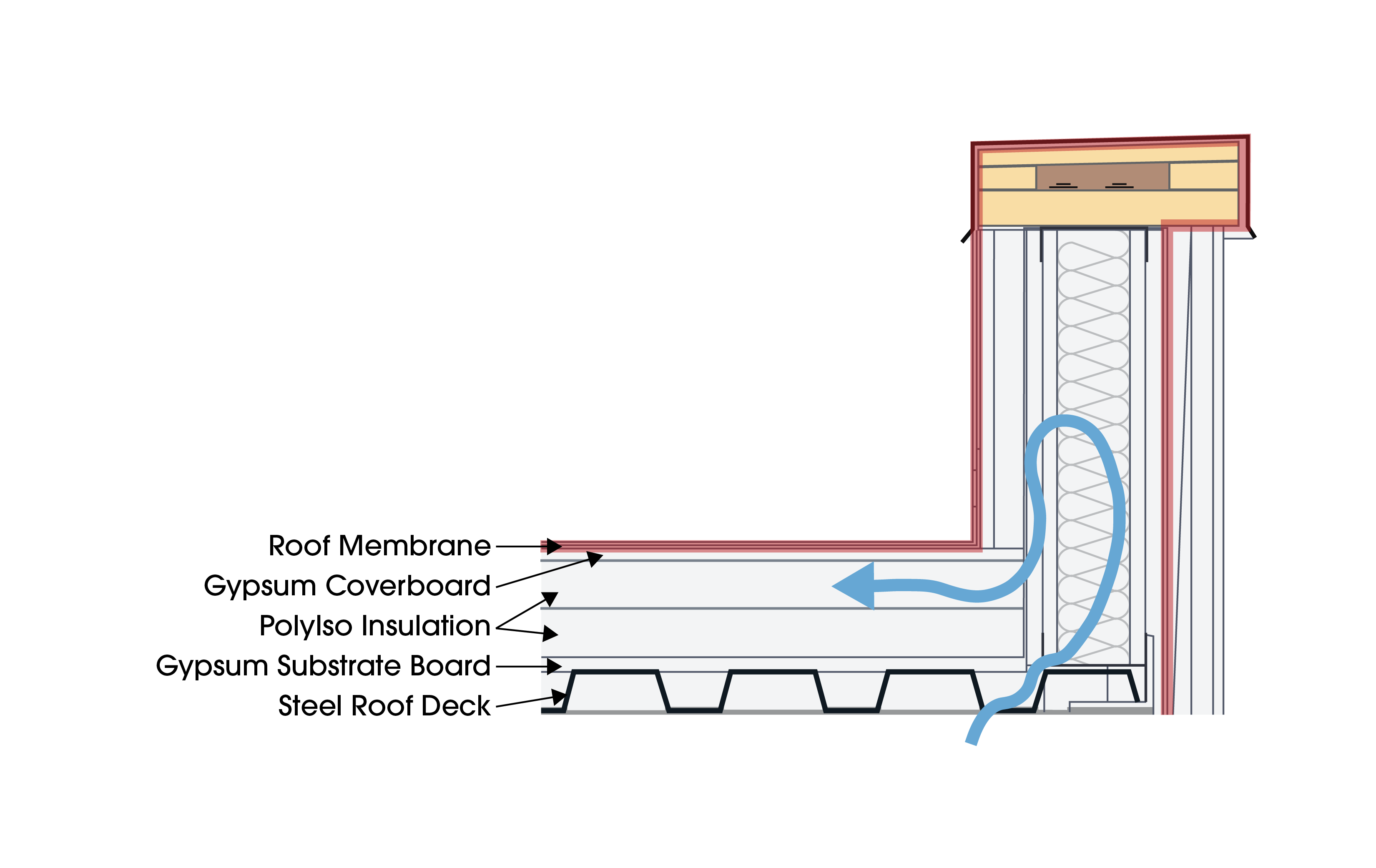
Figure courtesy of GAF
Figure 5. Roof membrane performing as air barrier in the assembly.
One option is to use the roof membrane as the air control layer in the assembly. This is shown in Figure 5. The roof membrane must be carried up over the parapet and overlap onto the wall. It then must be terminated and sealed to the wall air barrier material so that air and moisture leaks are prevented. In this scenario, interior air is allowed to intrude both into the roof assembly and the parapet, where there may be a risk of condensation.
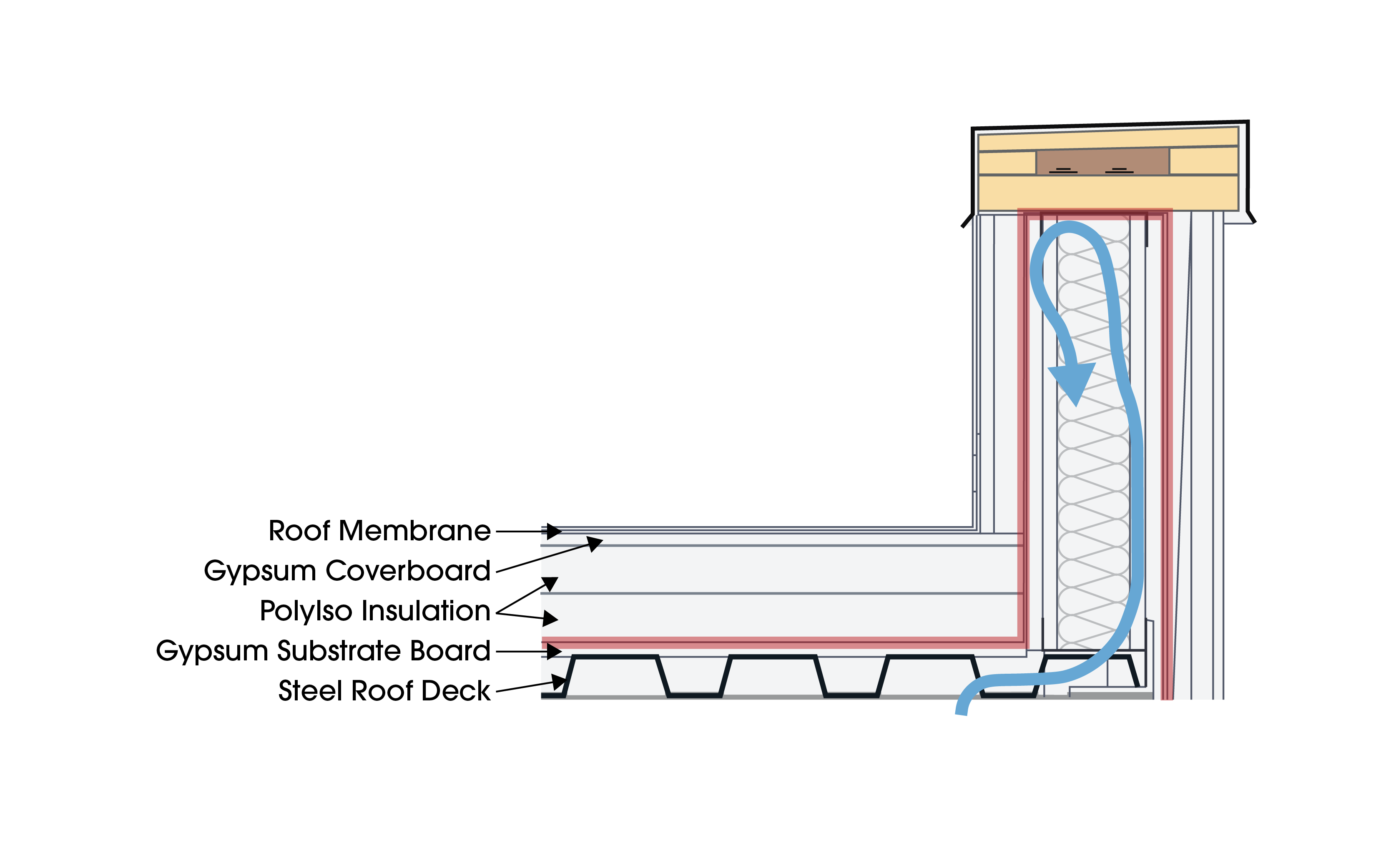
Figure courtesy of GAF
Figure 6. Self-adhered vapor retarder performing as air barrier, with air control layer going around the parapet.
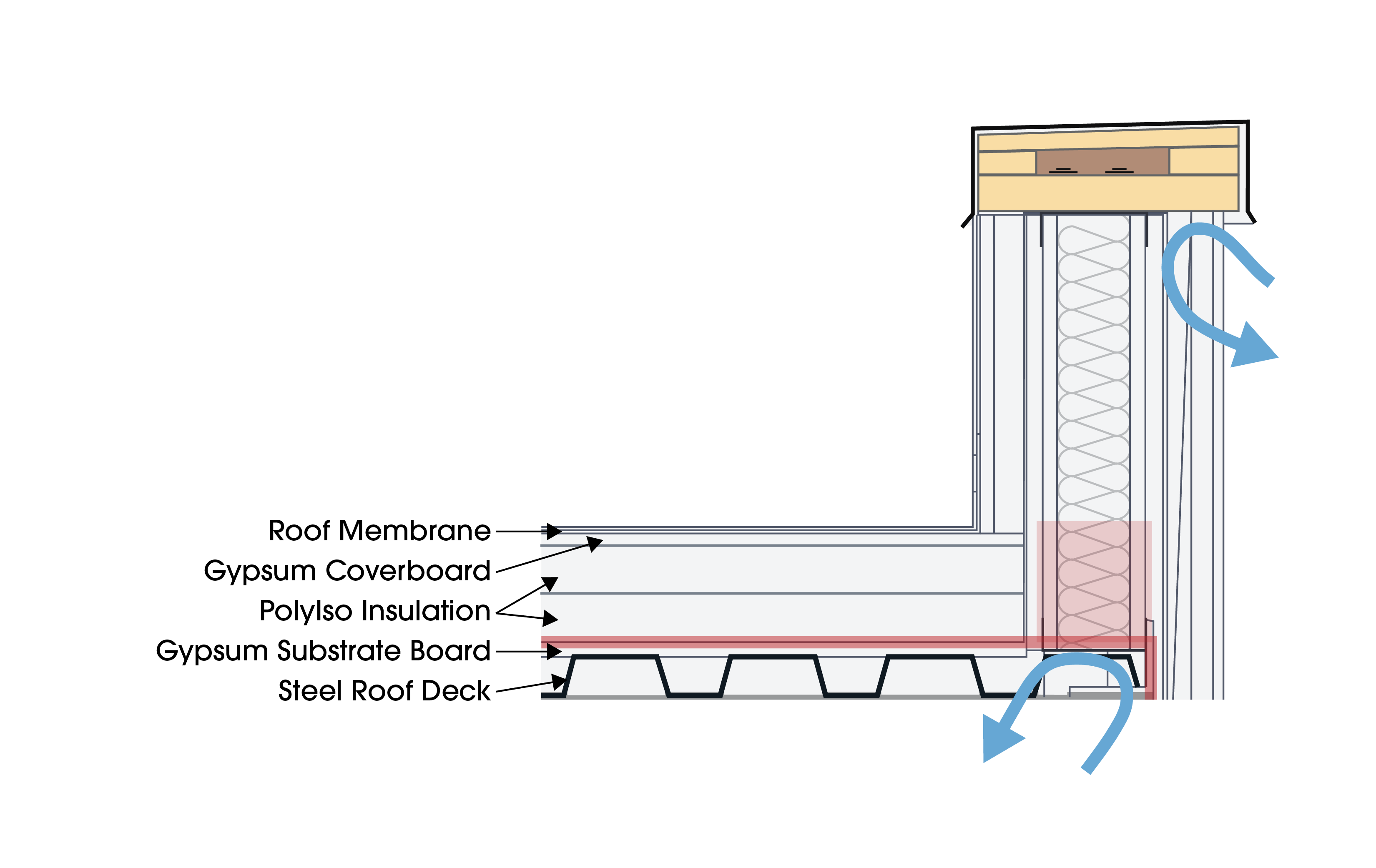
Figure courtesy of GAF
Figure 7. Self-adhered vapor retarder performing as the air barrier, tied to the wall air barrier and cutting the parapet off from the rest of the building.
The other option is to install the air control layer on or near the roof deck as shown in Figures 6 and 7. The air control layer shown is often called a “vapor retarder” by the product manufacturer, though it is performing as an air barrier in this scenario. Figure X shows how the air control layer can go over the top of the parapet and Figure Y demonstrates cutting off the base of the parapet entirely before tying into the air control layer on the wall. One benefit in these 2 cases is that they minimize the risk of air intrusion into the roof assembly, while the second option also reduces the risk of condensation at the top of the parapet. Additionally, the air control layer on the roof deck is more flexible and is easier to detail in an air tight transition to the wall air barrier.
Design Consideration for Vapor Retarders
Since vapor retarders are used to slow migration of water vapor by way of diffusion, they should be used in situations where controlling moisture mitigation and lowering condensation risks are important. A vapor retarder in an incorrect location can be just as problematic as not having one installed. When a vapor retarder is incorrectly placed, it can unintentionally trap moisture in the roof or wall system. Sometimes the best strategies to keep water vapor out can trap water vapor in – it is important to understand where moisture might accumulate and on what surface moisture could aggregate.
Designers can do moisture analysis to understand the implications of the placement of a vapor retarder in an assembly. Dew point analysis is commonly used for roof assemblies to determine where the dew point, or point of condensation, is likely to occur. Multiple calculations should be completed to ensure risks are tolerable throughout the year and not just during the winter. Another option is dynamic hygrothermal modeling which can estimate the risk of moisture accruing in the assembly as a whole, as well as individual materials over time. Hygrothermal analysis should be done by a trained individual to ensure accurate results.
Allowing the enclosure to dry is imperative. First, materials should be dry prior to installing vapor retarders in an assembly where moisture may be slow to diffuse out. Using a vapor retarder with some permeability can allow trapped moisture to dry. Next, placing a vapor retarder on the warm side of the insulation minimizes the risk of condensation from cool air accumulation, especially if it is also installed as an air barrier. Finally, avoiding two vapor retarders is a best practice. If two low-permeance vapor retarders are installed in an assembly without the innermost one being airtight, there is a risk of moisture entering by way of air leakage and not being able to diffuse back out of the system. Analyzing the full assembly to identify all vapor retarders will help, as many materials can act as a vapor retarder, potentially complicating the enclosure design.
It is vital that design professionals are alert to the possibility of trapped moisture in their design. Vapor retarders will perform said function whether they are detailed as an air barrier or not. If placed improperly, vapor retarders that trap moisture cause damage through deterioration of components and biological growth. Trapped moisture can damage coverboards as well as paper facers on insulation. This damage has the potential to compromise wind uplift resistance.
Conclusion
Bulk water leaks through the building enclosure, including both the roof and walls, can cause costly repairs. They can deteriorate the roof assembly and lessen its performance, including reducing R-values in the insulation, damaging interior finishes, and facilitating biological growth. Additionally, poorly controlled water ingress affects indoor air quality as mold growth in the roof assembly will find its way into the interior airspace of the building. The same is true for uncontrolled moisture vapor that is allowed to condense in an unmanaged area of the building enclosure assembly.
To be successful, the designated air and vapor control layers must be designed and installed to minimize uncontrolled moisture vapor. The air control layer should be the first priority after managing bulk water. Then, analysis can be completed to determine the need for and location of an independent vapor control layer. The materials, accessories and components that are part of the air and vapor control layers should be understood by everyone involved in the design, construction, and installation processes. Pre-construction meetings that review the control layers and identify the installation procedures are essential to prevent errors that can contribute to a poorly performing building. Careful planning and analysis of the assemblies, as well as continuous detailing at transitions can minimize risks and set a project up for success.
END NOTES
1Meyer, Benjamin. “Parapets Part 2: Navigating Codes.” GAF Roof Views Blog. GAF. January 24, 2020. Accessed May 28, 2025.
2Kirby, James R. “Air Barriers and Vapor Retarders: The Current Conundrum in the Roofing Industry.” GAF Roof Views Blog. GAF. September 10. 2018. Accessed May 29, 2025.
3Building Science Corporation, Build Boston—2005, Thermal and Air Leakage Control, ppt from Betsy Pettit, AIA.
4https://nvlpubs.nist.gov/nistpubs/TechnicalNotes/NIST.TN.2221.pdf.
5IIBEC Technical Advisory No. 020-2021: Roof Covering Systems and New Concrete Roof Decks. IIBEC TA-020-2021. May 15, 2021. International Institute of Building Enclosure Consultants. Accessed June 2, 2025.
6Ibid.
Andrea Wagner Watts is the Building Science Education Manager for GAF | Siplast Building & Roofing Science, engaging with industry professionals to provide guidance, technical support and education for roof and wall assemblies. With more than 15 years of experience in the industry, Andrea strives to improve the overall performance of the building enclosures through application innovation, product development and building science research. Andrea has published on building science, assembly interfaces, durability and resilience and holds multiple patents. She serves as the chair of the Air Barrier Association of America and chairs the ASTM E06 and D08 Task Groups on air barriers assemblies.