Photo courtesy of Andrew Thayer
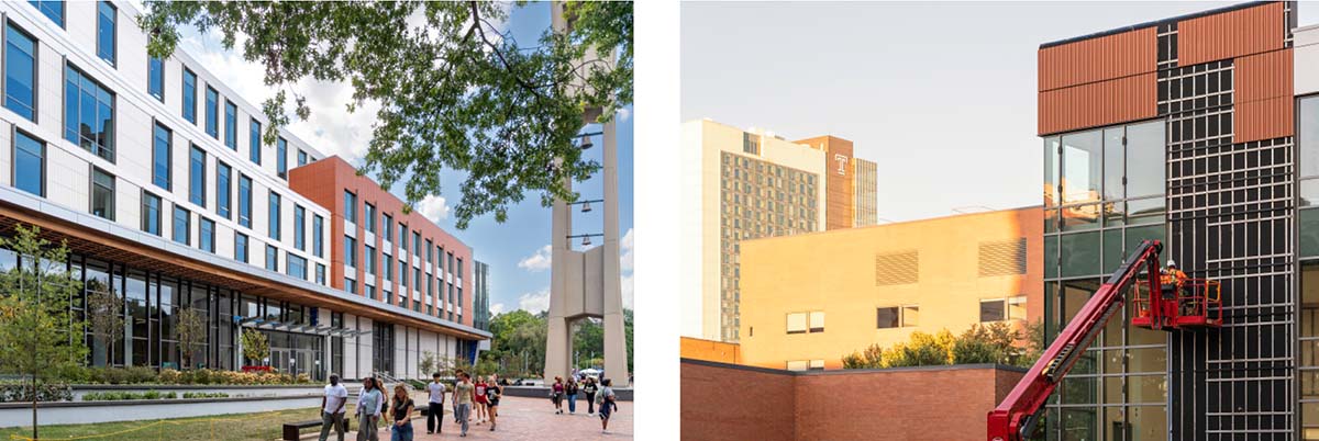
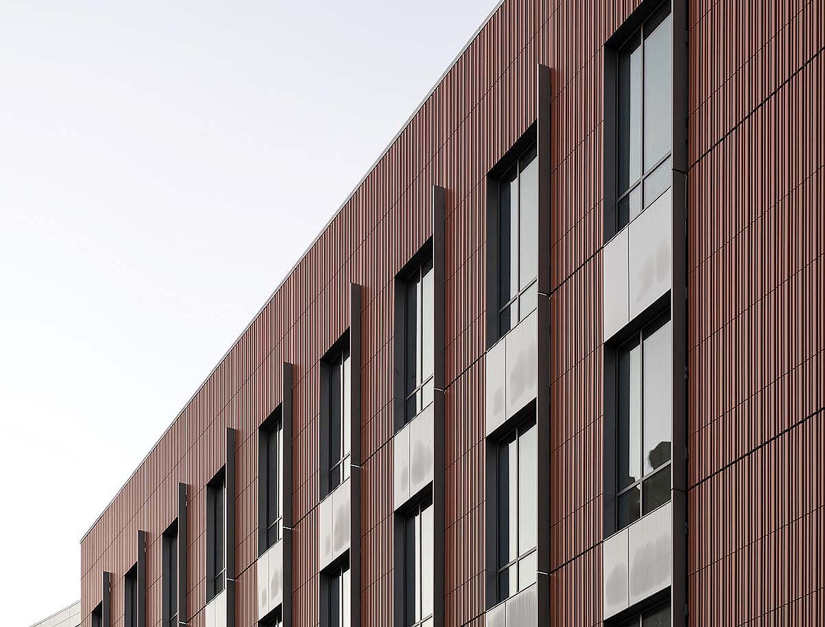
Paley Hall, Barnett College of Public Health, at Temple University in Philadelphia. Architects: SLAM Collaborative & PZS Architects.
Architects approach design from a range of perspectives suited to the individual project, the site, and the surrounding built context or the functional program. It is not atypical that at the beginning of a design process an architect’s approach alternates between inside-out (functional) and outside-in (formal). However, it is rare to see the design generated from the middle of the building enclosure system even though this assembly is critical to the success of both the interior function and exterior form of the architect’s vision. While it is understandable that the inner workings of a wall assembly are often not the first issues an architect will address, it is nonetheless one of the most critical to the overall success and longevity of the facade design.
This article will review various principles for rainscreen cladding approaches with a focus on how the exterior cladding is connected to the structural wall. These systems, in the middle of the wall assembly, are critical to the:
- creation of a wall that is resistant to moisture penetration and condensation,
- overall energy efficiency of the wall assembly,
- structural integrity of the building envelope,
- exterior appearance of the project, and
- quality of the interior environment and impact on the environment at-large.
RainScreen Wall Assemblies
Exterior walls must resist moisture penetration and can be generally classified as either a barrier system or a rainscreen assembly. Barrier systems are appropriate for certain applications and materials. They often rely on a single outer layer of material to resist all moisture and vapor penetration, and in some cases have no provision for a cavity or a weep system if moisture does get past the barrier. The integrity of such barrier systems relies on the primary material, mortars, or sealants in the joints to provide all the required moisture protection.
While there are viable barrier systems, many of us in the design and construction industry clearly remember the rather spectacular failure of the first generation of synthetic stucco barrier systems, which caused billions of dollars of damage to newly constructed buildings. These and other technical failures have spurred the growth of rainscreen wall assemblies as a safer and more effective alternative. The rainscreen assembly was already widely used in Europe, where many of the initial innovations were developed, supporting the rapid adoption of these systems in the US.
Rainscreen wall assemblies are a layered approach with a cavity. The approach is reminiscent of children being told to “dress in layers” so they stay both warm and dry. Arguably, masonry cavity walls are a type of rainscreen as they have many of the same components. With closed joints, they function more like a barrier wall with a fail-safe cavity that can evacuate the small amount of moisture that makes its way through or around the masonry cladding. However, they fail to address some of the other technical considerations better met by a rainscreen approach.
Rainscreen assemblies are defined by open joints in the cladding material over a passively ventilated cavity that is designed to allow moisture to freely drain back to the exterior. The open joints and the cavity allow for air pressure to equalize in the cavity, thus literally “taking the wind out of the sails” of the wind-driven rain. This divides the responsibility of resisting environmental forces so that the exterior cladding shields the barrier layer from wind-driven rain, absorbs UV radiation, and resists the deleterious effects of wind and abrasion. The weather barrier in the cavity is then left to simply resist moisture and air infiltration that is no longer under pressure, and any moisture entering the cavity will dry out via the passive ventilation of the cavity.
The performance of rainscreen assemblies has proven to be very effective in preventing moisture penetration into the backup wall, as well as effectively drying the assembly to the outside. As a result, the structure will last longer and be less prone to rust, rot, or decay, and the interior will be better protected from mold and mildew associated with moisture penetration.
The rainscreen assembly also allows for “continuous insulation” or CI, substantially improving the thermal performance of buildings when compared with cavity insulation within the backup wall. CI eliminates the effect of thermal bridging in stud-wall applications, allows for much higher effective insulation values and reductions in condensation by moving the dew-point further out in the wall assembly. Again, this allows for much better protection from mold and mildew within the wall.
Since the insulation layer in a CI system is located on the exterior of the moisture barrier, it needs to resist physical degradation and the potential reduction of effectiveness if it becomes moist. The insulation materials utilized will depend on the overall design of the wall and include mineral wool, extruded or expanded polystyrene, or polyisocyanurate.
The attachment of the insulation to the backup wall can be achieved by adhesives or mechanical fasteners and may be integrated with the attachment system utilized for the cladding.
Rainscreen assemblies have grown in popularity in part due to their ability to deliver a wide range of appearances. The term has also been attached, somewhat inappropriately, to systems that are “rainscreen-like,” which use relatively thin drainage mats but lack an open ventilated cavity. This article will focus on the types of rainscreen assemblies that include ventilation cavities and are suitable for larger buildings and wall surfaces.
A rainscreen wall assembly is generally comprised of the following key components:
- A structural backup wall(s), including sheathing
- An air and moisture barrier
- Insulation
- An attachment system, called a “sub-frame”
- Cladding
Backup walls can be steel studs, wood studs, cast-in-place concrete, or masonry, which are either load-bearing or are infill between structural elements that carry the primary building loads. This layer of the wall section is often where wiring, plumbing, and other systems are concealed, and includes exterior sheathing and interior finish surfaces. The cavities in this portion of the wall can be insulated, but this decision depends on the thermal properties of the overall wall assembly and the likely location of the dew point in relation to the wall section.
The exterior face of the backup wall sheathing is where the air and moisture barrier is located. This can be a separate membrane or be incorporated into the sheathing if the joints in the sheathing are properly sealed. The two common commercial system types are either fluid-applied or self-adhesive membranes. These products are generally “self-healing” when penetrated by fasteners. Since this is the primary moisture protection for the building, the detailing and execution of this layer is critical.
The attachment system or sub-framing connects the cladding to the backup wall. There are many available configurations for these systems that need to be coordinated with both the backup wall and the cladding selection. Systems typically are an assemblage involving some or all of the following: clip angles or brackets, hanger clips, vertical rails, and horizontal rails. The materials used for these systems and how they are attached to both the cladding and backup wall can have an outsized impact on the cost of the overall assembly, the design possibilities, and the thermal and structural performance of the wall system.
The exterior cladding for a rainscreen wall can include a wide range of materials, textures, and colors including:
- Natural stone
- Fiber cement
- Terracotta
- High pressure laminate (HPL)
- Fiber-reinforced polymer (FRP)
- Composites
- Porcelain/ceramic
- Plate metal
- Aluminum composite material (ACM)
One of the major benefits of the rainscreen system is that it can be used for a wide range of exterior cladding materials while providing a durable, energy-efficient, and watertight wall assembly.
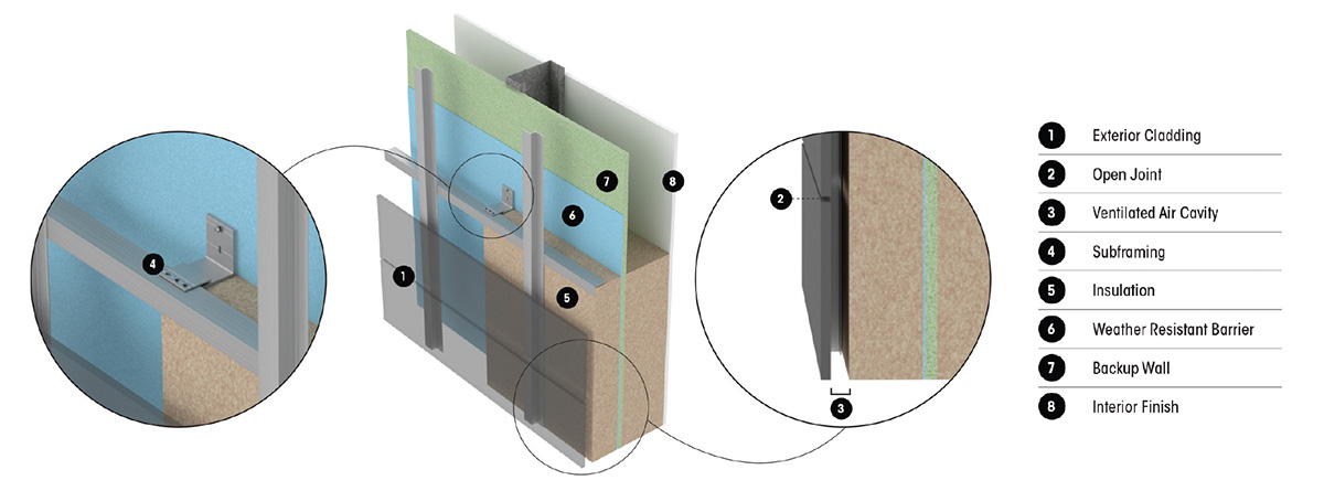
Diagram courtesy of exo Surfaces
Rainscreen assembly components.
History of Rainscreens
The idea of multi-layered exterior walls is not new. However, widespread adoption is fairly recent in the timescale of building techniques. Versions of masonry cavity walls were found to have been used in Ancient Greece and Rome. A closer version of today’s rainscreen concept was utilized in medieval times in Stave Churches in Norway. The oldest remaining example is the Urnes Stave Church, which dates to 1130 A.D.
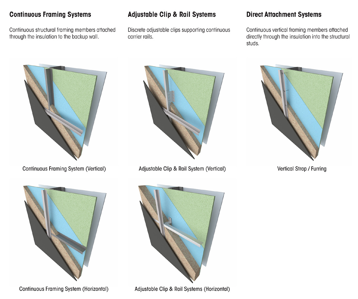
Image courtesy of exo Surfaces
Rainscreen attachment options and configurations of sub-framing systems.
Contemporary building science specifically addressed the issue of pressure equalization in walls in the 1940s through the 1970s. Again, from Norway, Øivind Birkeland referred to a “rain barrier” in a treatise published in the early 1960s. An often-cited research paper entitled “Rain Penetration and its Control,” written by G.K. Garden for the Canadian Building Digest, Division of Building Research in 1963, is one of the first uses of the term “open rainscreen.” “In essence, the outer layer is then an ‘open rainscreen’ that prevents wetting of the actual wall or air barrier of the building.”
The full document is available online and worth a full read. He makes the excellent point that while designers cannot guarantee that the building sub-surface will not have minor openings, the rainscreen configuration will eliminate the pressure which can drive moisture into these openings while providing a space for ventilation and drainage. Wall systems that utilize the rainscreen principle have become increasingly popular in the last 25 years. The percentage of non-residential buildings that utilize this principle in the United States has increased fivefold in the last 15 years.

Photos (clockwise from top left): ©Martin Graf; ©Rui Baiao; ©Byelikova; ©Hans Klamm – all images via Dreamstime.com
Historical precedents demonstrating early approaches to cavity construction, moisture management, and ventilated building envelopes.
The increased use of rainscreens is due in part to their effectiveness in mitigating moisture penetration, improving thermal performance, and reducing building structural loads. The ability to utilize a wide variety of exterior finishes opens up many possibilities for architects. While it needs to be carefully detailed and specified, a rainscreen wall can meet and exceed the requirements of today’s energy and life safety codes.
Rainscreen Sub-Framing Systems: Types and Materials
There are many configurations of sub-framing systems available, which are comprised of different shapes and materials. Strength, adjustability, fire resistance, and thermal properties all should be considered when designing or selecting a system.
Sub-framing systems can consist of multiple layers of framing with varied attachment techniques. Some components include:
Wall Brackets: These are typically fabricated “L” profiles and are relatively short in depth, ranging from as little as 1 inch to as much as 12 inches. The depth of the legs of the “L” will vary based on insulation depth, sub-structure, and overall system configuration. They can be mounted vertically to support vertical girts or horizontally to connect to horizontal framing members. Some are manufactured with a tab for stabilizing and holding the girt while finalizing the fastening which may be convenient for installation and fine adjustments.
Girts: These can be fastened directly to the backup wall or to a wall bracket. They are most typically an “L” angle, a “T” shape, a hat channel, or a “Z” shape. In a “single-layer” system they connect directly to the cladding panel, and in a “double-layer” system they connect to a secondary framing member that is then attached to the cladding panel. In all cases, a vertical ventilation cavity must be maintained.
Exterior Cladding Connectors: Concealed fastening of panels is achieved by using a French-cleat type hanger clip on the back of the panel, or by utilizing a panel with hooks, grooves, or channels in the panel itself. Hanger clips are typically attached to the back of panels with a “back screw” that relies on adhesive or expansion to make a structurally sound connection to the panel. Exposed fastening is achieved by screws or rivets, which can be color matched to the exterior panel, extending through the panel into the vertical or horizontal sub-framing.
Fasteners: A variety of self-drilling/self-tapping fasteners in a range of materials are used in these systems. Generally speaking, fasteners are required to be 300-Series stainless steel, with 400-Series steel or carbon steel being unacceptable. As with the rest of the system, the size and spacing of the fasteners must be engineered to the project requirements.
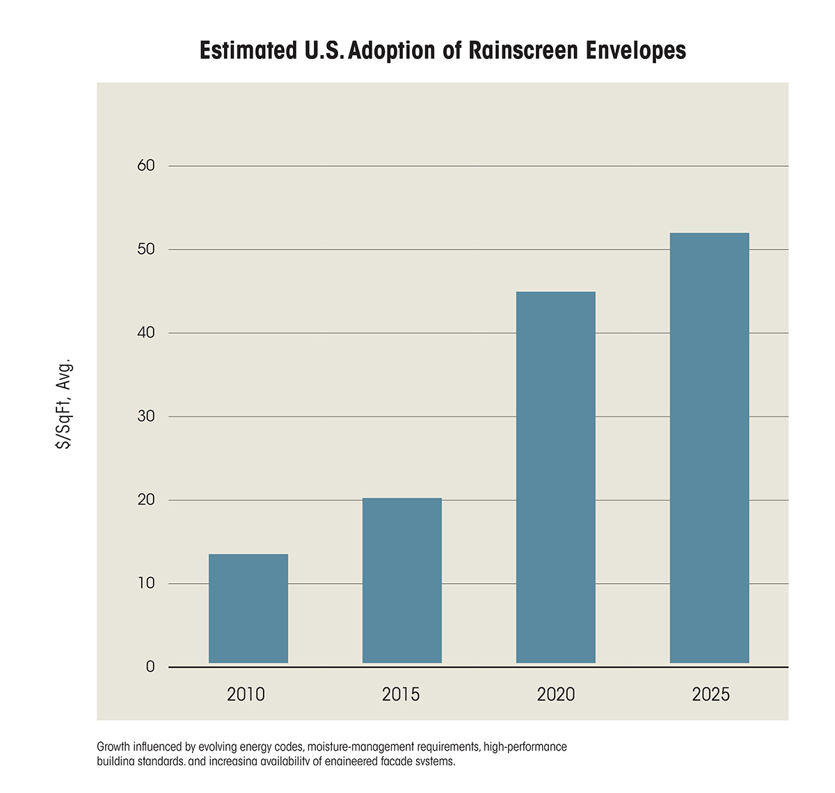
Graph courtesy of exo Surfaces
Use of rainscreens in non-residential buildings.
Typical materials used for sub-framing components include:
- Carbon steel – galvanized or ZAM
- Stainless Steel
- Aluminum
- Fiber-reinforced polymer (FRP)
Each material can be utilized in a sub-framing system as long as it is engineered to accommodate the project-specific design loads. It is important to note that strength results for FRP created through the pultrusion process will vary based on the manufacturer, and since it is created with a specific direction(s) of glass fibers, its strength will vary based on the orientation of the testing.
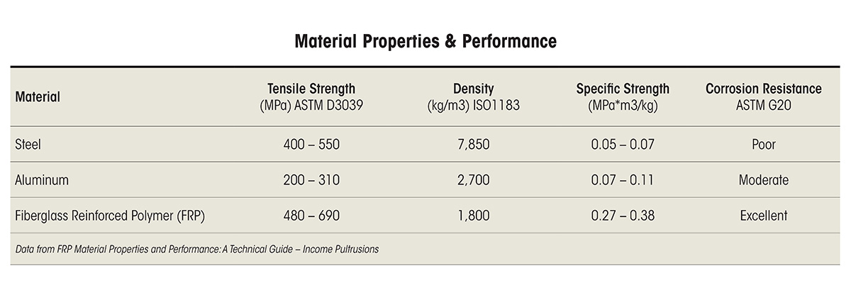
Graph courtesy of exo Surfaces
Data from FRP Material Properties and Performance: A Technical Guide – Income Pultrusions.
Photo courtesy of Andrew Thayer
Paley Hall, Barnett College of Public Health, at Temple University in Philadelphia. Architects: SLAM Collaborative & PZS Architects.
Architects approach design from a range of perspectives suited to the individual project, the site, and the surrounding built context or the functional program. It is not atypical that at the beginning of a design process an architect’s approach alternates between inside-out (functional) and outside-in (formal). However, it is rare to see the design generated from the middle of the building enclosure system even though this assembly is critical to the success of both the interior function and exterior form of the architect’s vision. While it is understandable that the inner workings of a wall assembly are often not the first issues an architect will address, it is nonetheless one of the most critical to the overall success and longevity of the facade design.
This article will review various principles for rainscreen cladding approaches with a focus on how the exterior cladding is connected to the structural wall. These systems, in the middle of the wall assembly, are critical to the:
- creation of a wall that is resistant to moisture penetration and condensation,
- overall energy efficiency of the wall assembly,
- structural integrity of the building envelope,
- exterior appearance of the project, and
- quality of the interior environment and impact on the environment at-large.
RainScreen Wall Assemblies
Exterior walls must resist moisture penetration and can be generally classified as either a barrier system or a rainscreen assembly. Barrier systems are appropriate for certain applications and materials. They often rely on a single outer layer of material to resist all moisture and vapor penetration, and in some cases have no provision for a cavity or a weep system if moisture does get past the barrier. The integrity of such barrier systems relies on the primary material, mortars, or sealants in the joints to provide all the required moisture protection.
While there are viable barrier systems, many of us in the design and construction industry clearly remember the rather spectacular failure of the first generation of synthetic stucco barrier systems, which caused billions of dollars of damage to newly constructed buildings. These and other technical failures have spurred the growth of rainscreen wall assemblies as a safer and more effective alternative. The rainscreen assembly was already widely used in Europe, where many of the initial innovations were developed, supporting the rapid adoption of these systems in the US.
Rainscreen wall assemblies are a layered approach with a cavity. The approach is reminiscent of children being told to “dress in layers” so they stay both warm and dry. Arguably, masonry cavity walls are a type of rainscreen as they have many of the same components. With closed joints, they function more like a barrier wall with a fail-safe cavity that can evacuate the small amount of moisture that makes its way through or around the masonry cladding. However, they fail to address some of the other technical considerations better met by a rainscreen approach.
Rainscreen assemblies are defined by open joints in the cladding material over a passively ventilated cavity that is designed to allow moisture to freely drain back to the exterior. The open joints and the cavity allow for air pressure to equalize in the cavity, thus literally “taking the wind out of the sails” of the wind-driven rain. This divides the responsibility of resisting environmental forces so that the exterior cladding shields the barrier layer from wind-driven rain, absorbs UV radiation, and resists the deleterious effects of wind and abrasion. The weather barrier in the cavity is then left to simply resist moisture and air infiltration that is no longer under pressure, and any moisture entering the cavity will dry out via the passive ventilation of the cavity.
The performance of rainscreen assemblies has proven to be very effective in preventing moisture penetration into the backup wall, as well as effectively drying the assembly to the outside. As a result, the structure will last longer and be less prone to rust, rot, or decay, and the interior will be better protected from mold and mildew associated with moisture penetration.
The rainscreen assembly also allows for “continuous insulation” or CI, substantially improving the thermal performance of buildings when compared with cavity insulation within the backup wall. CI eliminates the effect of thermal bridging in stud-wall applications, allows for much higher effective insulation values and reductions in condensation by moving the dew-point further out in the wall assembly. Again, this allows for much better protection from mold and mildew within the wall.
Since the insulation layer in a CI system is located on the exterior of the moisture barrier, it needs to resist physical degradation and the potential reduction of effectiveness if it becomes moist. The insulation materials utilized will depend on the overall design of the wall and include mineral wool, extruded or expanded polystyrene, or polyisocyanurate.
The attachment of the insulation to the backup wall can be achieved by adhesives or mechanical fasteners and may be integrated with the attachment system utilized for the cladding.
Rainscreen assemblies have grown in popularity in part due to their ability to deliver a wide range of appearances. The term has also been attached, somewhat inappropriately, to systems that are “rainscreen-like,” which use relatively thin drainage mats but lack an open ventilated cavity. This article will focus on the types of rainscreen assemblies that include ventilation cavities and are suitable for larger buildings and wall surfaces.
A rainscreen wall assembly is generally comprised of the following key components:
- A structural backup wall(s), including sheathing
- An air and moisture barrier
- Insulation
- An attachment system, called a “sub-frame”
- Cladding
Backup walls can be steel studs, wood studs, cast-in-place concrete, or masonry, which are either load-bearing or are infill between structural elements that carry the primary building loads. This layer of the wall section is often where wiring, plumbing, and other systems are concealed, and includes exterior sheathing and interior finish surfaces. The cavities in this portion of the wall can be insulated, but this decision depends on the thermal properties of the overall wall assembly and the likely location of the dew point in relation to the wall section.
The exterior face of the backup wall sheathing is where the air and moisture barrier is located. This can be a separate membrane or be incorporated into the sheathing if the joints in the sheathing are properly sealed. The two common commercial system types are either fluid-applied or self-adhesive membranes. These products are generally “self-healing” when penetrated by fasteners. Since this is the primary moisture protection for the building, the detailing and execution of this layer is critical.
The attachment system or sub-framing connects the cladding to the backup wall. There are many available configurations for these systems that need to be coordinated with both the backup wall and the cladding selection. Systems typically are an assemblage involving some or all of the following: clip angles or brackets, hanger clips, vertical rails, and horizontal rails. The materials used for these systems and how they are attached to both the cladding and backup wall can have an outsized impact on the cost of the overall assembly, the design possibilities, and the thermal and structural performance of the wall system.
The exterior cladding for a rainscreen wall can include a wide range of materials, textures, and colors including:
- Natural stone
- Fiber cement
- Terracotta
- High pressure laminate (HPL)
- Fiber-reinforced polymer (FRP)
- Composites
- Porcelain/ceramic
- Plate metal
- Aluminum composite material (ACM)
One of the major benefits of the rainscreen system is that it can be used for a wide range of exterior cladding materials while providing a durable, energy-efficient, and watertight wall assembly.
Diagram courtesy of exo Surfaces
Rainscreen assembly components.
History of Rainscreens
The idea of multi-layered exterior walls is not new. However, widespread adoption is fairly recent in the timescale of building techniques. Versions of masonry cavity walls were found to have been used in Ancient Greece and Rome. A closer version of today’s rainscreen concept was utilized in medieval times in Stave Churches in Norway. The oldest remaining example is the Urnes Stave Church, which dates to 1130 A.D.
Image courtesy of exo Surfaces
Rainscreen attachment options and configurations of sub-framing systems.
Contemporary building science specifically addressed the issue of pressure equalization in walls in the 1940s through the 1970s. Again, from Norway, Øivind Birkeland referred to a “rain barrier” in a treatise published in the early 1960s. An often-cited research paper entitled “Rain Penetration and its Control,” written by G.K. Garden for the Canadian Building Digest, Division of Building Research in 1963, is one of the first uses of the term “open rainscreen.” “In essence, the outer layer is then an ‘open rainscreen’ that prevents wetting of the actual wall or air barrier of the building.”
The full document is available online and worth a full read. He makes the excellent point that while designers cannot guarantee that the building sub-surface will not have minor openings, the rainscreen configuration will eliminate the pressure which can drive moisture into these openings while providing a space for ventilation and drainage. Wall systems that utilize the rainscreen principle have become increasingly popular in the last 25 years. The percentage of non-residential buildings that utilize this principle in the United States has increased fivefold in the last 15 years.
Photos (clockwise from top left): ©Martin Graf; ©Rui Baiao; ©Byelikova; ©Hans Klamm – all images via Dreamstime.com
Historical precedents demonstrating early approaches to cavity construction, moisture management, and ventilated building envelopes.
The increased use of rainscreens is due in part to their effectiveness in mitigating moisture penetration, improving thermal performance, and reducing building structural loads. The ability to utilize a wide variety of exterior finishes opens up many possibilities for architects. While it needs to be carefully detailed and specified, a rainscreen wall can meet and exceed the requirements of today’s energy and life safety codes.
Rainscreen Sub-Framing Systems: Types and Materials
There are many configurations of sub-framing systems available, which are comprised of different shapes and materials. Strength, adjustability, fire resistance, and thermal properties all should be considered when designing or selecting a system.
Sub-framing systems can consist of multiple layers of framing with varied attachment techniques. Some components include:
Wall Brackets: These are typically fabricated “L” profiles and are relatively short in depth, ranging from as little as 1 inch to as much as 12 inches. The depth of the legs of the “L” will vary based on insulation depth, sub-structure, and overall system configuration. They can be mounted vertically to support vertical girts or horizontally to connect to horizontal framing members. Some are manufactured with a tab for stabilizing and holding the girt while finalizing the fastening which may be convenient for installation and fine adjustments.
Girts: These can be fastened directly to the backup wall or to a wall bracket. They are most typically an “L” angle, a “T” shape, a hat channel, or a “Z” shape. In a “single-layer” system they connect directly to the cladding panel, and in a “double-layer” system they connect to a secondary framing member that is then attached to the cladding panel. In all cases, a vertical ventilation cavity must be maintained.
Exterior Cladding Connectors: Concealed fastening of panels is achieved by using a French-cleat type hanger clip on the back of the panel, or by utilizing a panel with hooks, grooves, or channels in the panel itself. Hanger clips are typically attached to the back of panels with a “back screw” that relies on adhesive or expansion to make a structurally sound connection to the panel. Exposed fastening is achieved by screws or rivets, which can be color matched to the exterior panel, extending through the panel into the vertical or horizontal sub-framing.
Fasteners: A variety of self-drilling/self-tapping fasteners in a range of materials are used in these systems. Generally speaking, fasteners are required to be 300-Series stainless steel, with 400-Series steel or carbon steel being unacceptable. As with the rest of the system, the size and spacing of the fasteners must be engineered to the project requirements.
Graph courtesy of exo Surfaces
Use of rainscreens in non-residential buildings.
Typical materials used for sub-framing components include:
- Carbon steel – galvanized or ZAM
- Stainless Steel
- Aluminum
- Fiber-reinforced polymer (FRP)
Each material can be utilized in a sub-framing system as long as it is engineered to accommodate the project-specific design loads. It is important to note that strength results for FRP created through the pultrusion process will vary based on the manufacturer, and since it is created with a specific direction(s) of glass fibers, its strength will vary based on the orientation of the testing.
Graph courtesy of exo Surfaces
Data from FRP Material Properties and Performance: A Technical Guide – Income Pultrusions.
Stainless steel is a good choice for sub-framing systems. It has a long useful life, excellent corrosion resistance, and good thermal properties. Due to its high cost, it is generally reserved for use where exposure to a corrosive environment is a significant factor, such as at a coastal location. It is heavy compared to the alternatives, increasing transportation costs.
Aluminum is also a good choice for sub-framing systems. Aluminum is cost effective, high strength, easily handled due to its light weight, and has good corrosion resistance. The ease of extruding and machining aluminum means a larger variety of parts and components can be produced cost-effectively. Taken together, it is easy to see why it is the most commonly used material for sub-framing system components.
However, both steel and aluminum have high thermal conductivity, which can present challenges when a high level of thermal performance is required, especially where the wall depth is limited.
FRP or glass-fiber-reinforced polymer components are relatively new to the industry and offer significant advantages due to both a high strength-to-weight ratio and low thermal conductivity. These components are proprietary to each manufacturer, with the best versions using a pultrusion process which results in higher strength in multiple orientations of the structural shape. FRP components are lightweight, strong, have excellent thermal properties, and excellent long-term corrosion resistance. While somewhat more costly than their aluminum counterparts, their long expected useful life and high performance make for an excellent long-term value. A comparative cost analysis is provided below.
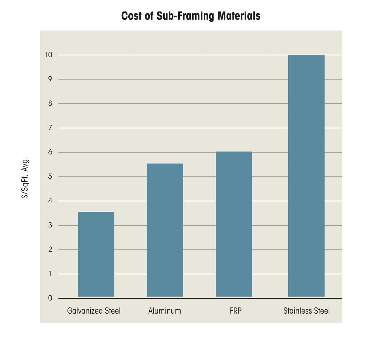
Graph courtesy of exo Surfaces
Cost of sub-framing materials.
When comparing the cost of rainscreen systems to other options like full depth brick masonry, several factors should be considered. Rainscreen systems are lighter in overall weight, resulting in a lighter primary frame and foundation, thus saving costs on the base building. In my personal experience, we explored using a fiber cement rainscreen cladding in lieu of full depth brick masonry as part of a value engineering process and were able to achieve a 20 percent savings. This solution also added some variety and articulation to the building’s exterior, which was preferred by the client.
System types have inherent limitations based on how they are installed, which can impact the structural, thermal, and aesthetic results. The ability to adjust the sub-framing to accommodate variations in the backup structure is important to ensure that the cladding has a smooth and flat appearance, but many panel systems may fail if over-stressed due to poorly installed sub-framing. This is especially important when the cladding is smooth, metallic, or reflective, as uneven sub-framing will result in “oil-canning” or distortion in the finished exterior surface. Further, some cladding materials such as stone and fiber-cement are brittle and may break if the sub-framing is not installed flat.
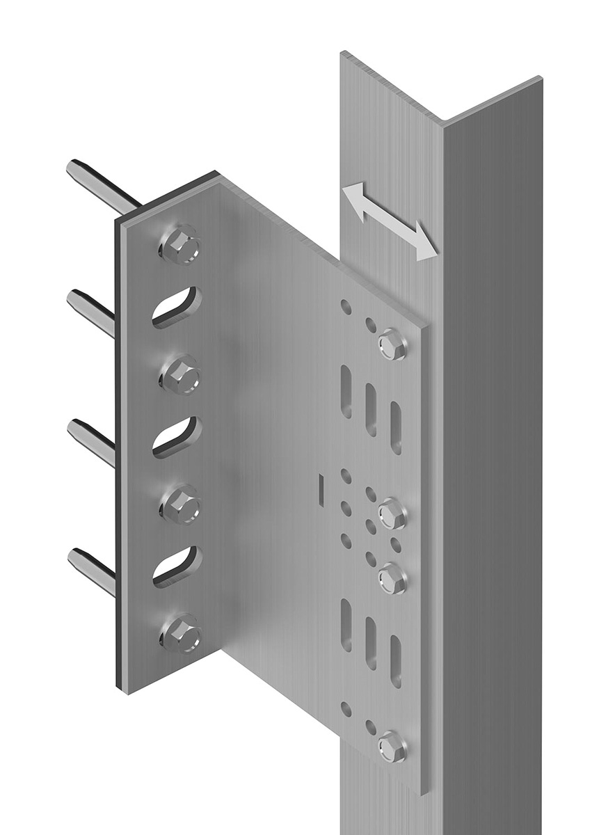
Image courtesy of exo Surfaces
Example of an adjustable bracket.
Concrete masonry installation tolerances are +/-¼ inch both horizontal and vertical over a 10-foot length, with a maximum of +/-½ inch or +/-¾ inch over the length and height of the building wall. Cold-formed metal framing typically has an installation tolerance of +/-1/8 inch over a 10-foot length, and while wood stud framing requires installation tolerances that are similar to concrete masonry, it is often installed out of tolerance by a substantial margin. For multi-story buildings, it is often the slab edge that presents the largest challenge for plumb and flat alignment with the backup construction.
The sub-framing system needs to be able to correct for flatness and plumb so that the exterior cladding is flat and level to a tolerance of +/-1/16 inch over the length or width of the panel. This can be easily accomplished with a “clip and rail” type system. These systems allow for “self-shimming” as the framing is installed. When laser scanning or expert measurement is used to determine the deformations of the backup wall prior to ordering materials, and when laser levels are used during installation, the result can be very precise and efficient.
As practitioners, we know that construction is consistently imperfect. There are various ways to adjust the attachment of the cladding to the sub-frame, depending on the cladding type and manufacturer that is selected. It is important to ask the manufacturer and designer of the sub-framing system how the cladding and sub-frame can be adjusted as it is installed – in height, width and depth – so that the joint spacing and alignment meets your design goals. Wall brackets should be used with both round and slotted holes to allow for varying attachment points. Absent a viable method for adjusting the sub-framing to meet the requirements of the cladding, you are most likely to end up with an unsatisfactory result.
It is also important to understand that since most systems have a specific sequence of installation, it is often not possible to adjust the first areas that were installed later unless you remove all of the panels that were installed afterward. So both the adjustability of the system and the acceptable installation tolerances need to be established at the specification and early design stages, not after completion as part of the punch list. With minor exceptions, if the completed facade has some unacceptable joints, out-of-plane panels, or other visual discrepancies, you may have to simply accept the results.
Some systems incorporate framing members that are screwed directly through the insulation into the backup structure. This may be acceptable for low-rise or limited areas but is often problematic in a number of ways. It works better with rigid insulation, but with mineral fiber insulation it basically results in screwing your exterior cladding through a soft pillow-like material, resulting in an uneven and difficult-to-adjust exterior sub-framing surface.
Designing with Sub-Framing Systems for Rainscreen Walls
As mentioned in the introduction to this article, often the Architect’s first step as the leader of the design team is to establish your exterior cladding selection(s). As the wall section is developed, you will work with your engineering consultants on the primary structural frame and backup wall construction. While the details of a sub-framing system are typically fleshed out in the design development phase, you will need to establish the insulation and cavity depth in order to establish an overall wall thickness in the earlier stages of design.
Insulation depths will be guided by the energy code in your climate zone and cavity depth by the sub-framing system you have selected. A clear cavity depth suitable for both drainage and ventilation should be in the range of 3/4 inch to 1-1/2 inches. Architects who work with masonry cavity walls are familiar with larger cavity depths which are necessary to allow for the mason’s hand and trowel to keep mortar out of the cavity. The specific size of the cavity necessary to allow for back ventilation and the efficacy of pressure equalization in an open joint rainscreen assembly is a subject of some debate in the building science community. Since this is dependent in part on the size of the joint between the cladding elements, it is best if you work with the cladding supplier to determine the appropriate depth.
The orientation of the sub-framing system, vertical or horizontal, will depend on the cladding material selection, backup wall type, and cladding fastening technique. Back-mounted concealed attachment may require a larger cavity, and in some cases will require the outer sub-framing member to be mounted horizontally. Horizontal framing members in the cavity should be shaped and installed so that they permit vertical ventilation, and when possible, so they do not catch water. Hat-shaped profiles, shapes with perforations, and inverted “L” profiles are good choices.
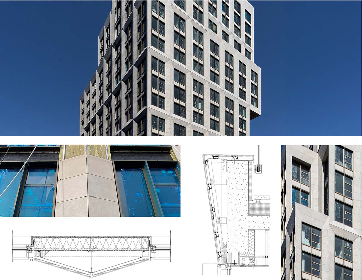
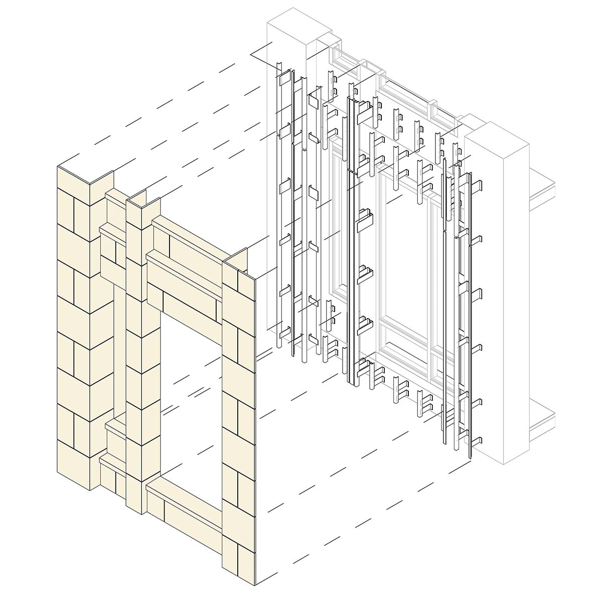
The exterior form of the building can be shaped with the primary structural elements or with the sub-framing system. When it is accomplished with the sub-framing system as in the image below, it can simplify the primary framing and backup system and allow the folded and angled form of the exterior cladding to be accomplished with the lighter weight of the sub-framing assembly. Of course, this type of application requires that the Architect coordinate with both the structural engineer and the manufacturer who is designing the specialty sub-framing system.
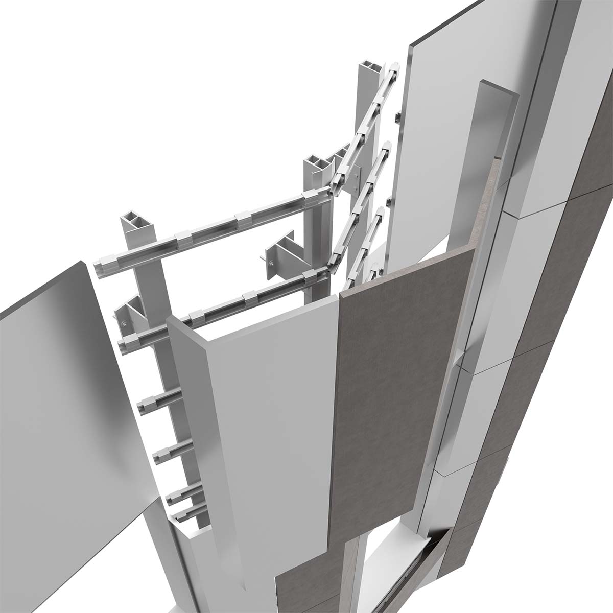
Image courtesy of exo Surfaces
Sub-framing used to create exterior shape of the cladding.
Some diligence is also required at corners, openings (door and window), and transitions between materials. Some claddings can provide their own returns, such as with bonded corners. In most cases, the returns are provided as a part of the window and/or door system’s formed metal trim. When the cladding material is chosen for returns, the sub-framing system will generally need to support it. Again, this will depend on the exterior cladding selection and the attachment method.
For all systems, it is absolutely critical to provide an exit path for moisture that does make its way into the cavity. This should incorporate waterproof flashing in the bottom of wall sections and above all interruptions in the facade at windows, doors, and other openings. The drainage pathways are typically only carrying droplets, not bulk water, so the drainage system needs to be complete but not large.
Thermal Performance of Rainscreen Wall Assemblies
The energy impact of sub-framing systems on the overall building envelope can be significant. The critical issue is how much conductive heat loss flows through the sub-framing system, or what is traditionally known as thermal bridging. Some review and general background on this critical issue is helpful to best understand how it applies to rainscreen assemblies.
Thermal Bridge Definition: The International Energy Conservation Code (2024 IECC) defines Thermal Bridging as “An element or interface of elements that has a higher thermal conductivity than the surrounding building thermal envelope, which creates a path of least resistance for heat transfer.”
How you think about an issue and what it is called does affect your perception of it. Bridges typically connect places and people on a point-to-point basis and are viewed positively. It is for this reason that I would argue that thermal bridges should be thought of as, and called, leaks or short circuits.
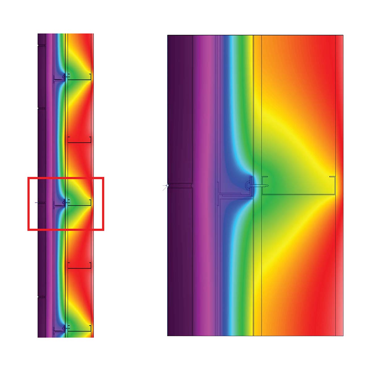
Image courtesy of exo Surfaces
Image of thermal model with thermal bridging, leaking at sub-framing attachment points. The impact of the thermal conductivity affects a much larger area than the actual contact area of the sub-framing to the sheathing.
A roof leak at a nail hole is very small, but it can continually damage a much larger area below. A short circuit is a single isolated problem that can cause the failure of a larger portion of the electrical system. These are more accurate models of what happens when conductive heat loss is channeled through the building envelope. Thermal models visually demonstrate precisely this type of impact. Given that these leaks can lower the overall R-value of a wall by 30-50 percent and can cause damaging condensation to occur, they need to be taken very seriously.
In conventional, simplified modeling, the insulation value of each component of the building envelope is area weighted to arrive at an overall value. While the overall surface area of thermal leaks is typically quite small, the area weighting technique for evaluating their impact is imprecise and produces an inaccurate result. Thermal leaks are not linear or parallel conductive heat transmission but are multi-dimensional.
Thermal and energy modeling are markedly different processes. Thermal modeling is focused on heat transmission through the building envelope, while energy modeling more broadly includes solar heat gain, patterns of use, mechanical equipment, and so on. The best approach to more accurately evaluate the effect of thermal leaks is to have thermal models completed for specific conditions, and then extrapolate that effect to include all occurrences of these various conditions. Ideally, a comprehensive thermal model of the entire enclosure would yield the most accurate overall data. However, this process is exhaustive and often not realistic for typical projects with normal timelines and budgets. It is hopeful to think that with the development of AI and the increasing public and client awareness of the importance of the building envelope, comprehensive thermal modeling of the building envelope will gain traction. The thermal conductivity of the materials used in sub-framing systems is an important factor in the magnitude of the thermal leakage taking place in rainscreen assemblies.
Graph courtesy of exo Surfaces
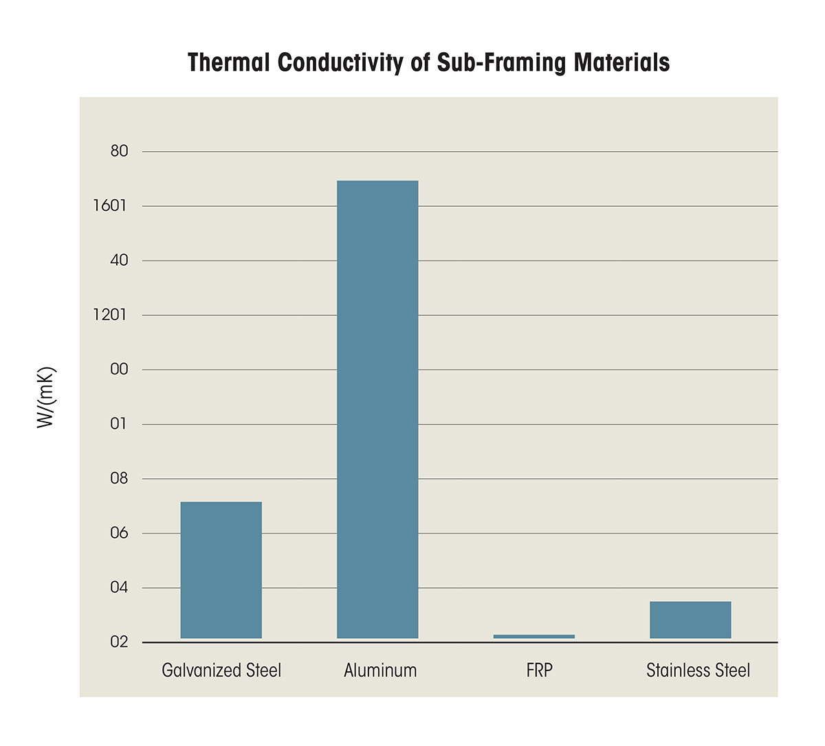
Thermal conductivity of sub-framing materials.
The data above is for the material alone and not the entire system. As you can see, FRP is by far the best material from a thermal conductivity viewpoint. If the vertical or horizontal framing member is located on the outside of the insulation layer, its thermal conductivity may not be as critical, and its strength or other properties may be more important. If this member is serving to also retain the insulation, or if it penetrates the insulation layer, its thermal conductivity may be an important factor in material decision making.
The data obtained from thermal models for the leaks that occur due to the wall assembly design will provide information needed to “de-rate” or reduce the effective R-value of the wall assembly. Materials with higher thermal conductivity result in a need to add insulation to achieve the code-compliant insulation level. This is achieved through one or a combination of insulation on the exterior of the backup wall (CI) and in the interior of a stud cavity. As a result, materials with higher thermal conductivity will result in a thicker overall wall section that is generally more costly.
Passive house requirements and some energy codes require that insulation and the air barrier be continuous.
Cladding Supports (C402.7.2): The International Energy Conservation Code (2024 IECC) specifies that “Linear elements supporting opaque cladding shall be offset from the structure with attachments that allow continuous insulation… to pass behind the cladding support element except at the point of attachment” except via approved design which accounts for the thermal bridge.
The requirement for continuity is challenging if the impact of the thermal leak or bridge is extensive due to the use of a continuous, highly thermally conductive material. Typical methods of compliance in this scenario involve added insulation either inside the wall cavity, or on top of the bridged exterior insulation layer. This needs to be balanced between the interior and exterior, and will in some cases result in the dew point occurring within the wall section, which can accelerate deterioration of the sub-framing, and cause damage to the building including interior finishes, and may promote fungus and mold growth. If water is allowed to penetrate the wall assembly, or if the insulation and attachment approach moves the dew point into the wall cavity, it will allow for the growth of mold or mildew over time. This can take time to become evident but will have an insidious and perpetual impact on the indoor environment, especially air quality.
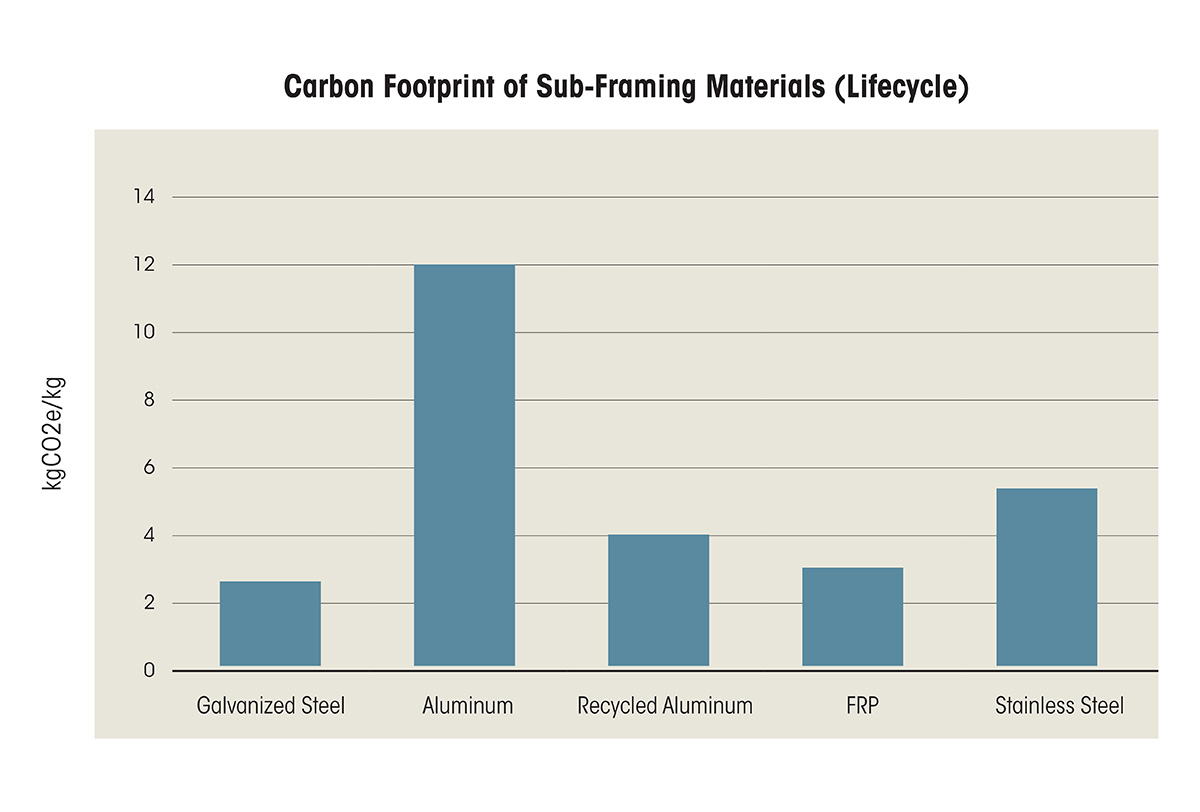
The environmental impact and the overall life-cycle of the materials chosen are also important considerations when selecting a sub-framing system. The expected useful life of the materials and systems also needs to be factored into the environmental impact of the product selection. While FRP is not currently recyclable, it is likely that since this material is becoming so widely used, a method of re-using these thermoset composites will be developed.
Graph courtesy of exo Surfaces
Carbon impact of materials used in sub-framing systems.
Photos courtesy of exo Surfaces
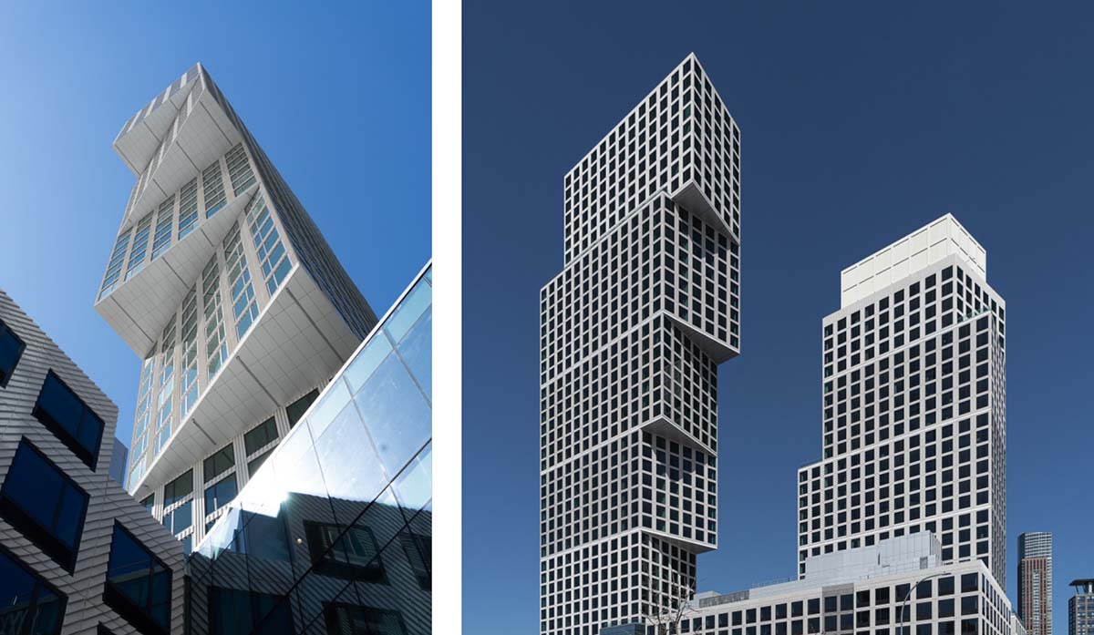
Photos and details showing how a complex shape can be created with sub-framing. The Westley (2461 Broadway) Location: New York, City
Architect: ODA Architecture.
The thoughtful application of a rainscreen wall assembly with proper thermal isolation allows architects to create innovative exterior shapes without the risk of water penetration at each corner and fold in the exterior wall.
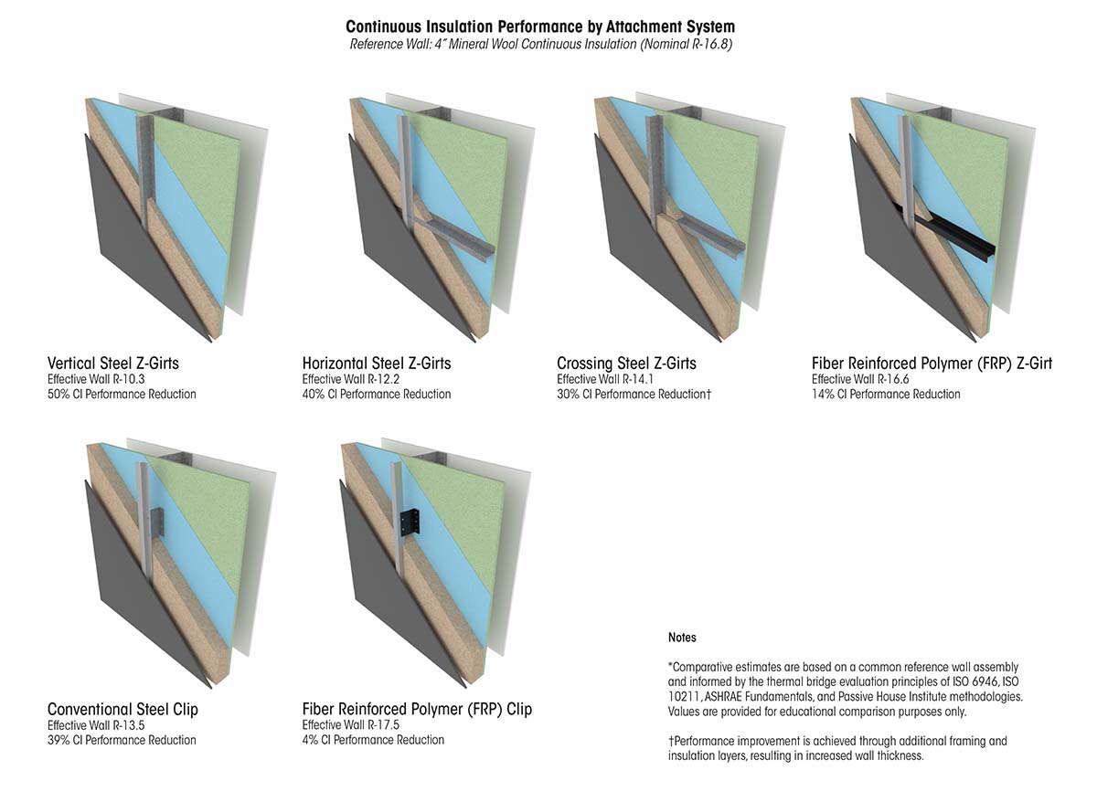
Image courtesy of exo Surfaces
Conductive girts and clips will de-rate the insulation’s effectiveness.
Specifying
Sub-framing systems and exterior cladding are often not made of similar materials nor are they produced in a similar manner, and as a result, they are frequently made by different manufacturers. This is not ideal for architects and specifiers who prefer a single source of responsibility and coordination for the various elements of a building facade. Both cladding producers and sub-framing manufacturers have created alliances to provide this single source of responsibility, but this can limit the design approaches available to the architect. This is why it is essential that the architect and specifier understand the characteristics of all the key elements of a rainscreen assembly.
With the rainscreen assembly becoming very popular, there has been a significant expansion in the number of firms producing sub-framing components. In a recent interview with Rob Haley, PE of Thermal Bridging Solutions, who has over 14 years of experience specifically addressing the issue of conductive heat loss and designing sub-framing systems, he recounted how there were originally only two manufacturers of sub-framing systems, and now there are over 25 suppliers for architects to review and consider. His specialized experience is available to architects as a consultant and as a pioneering inventor of some key components of modern sub-framing systems. With or without the assistance of a specialty consultant, it is advisable for architects to specify both the cladding and the sub-framing system, and to require that the producer of the sub-framing system take responsibility for the engineering (delegated design) of the overall assembly. Since the primary structural components of the system are in the sub-framing, and many of them are proprietary to a single manufacturer, this is the best path to a successful installation.
Architects increasingly need to rely on the “delegated design” approach as building systems continue to become more complex. This is the same approach that has been in place for many years for lightweight metal framing, structural steel connections, curtain wall design, and other specialized and proprietary systems. These factors are also the same conditions that are pushing the design and construction industry towards a more collaborative “integrated project delivery” or IPD approach. Many of the sub-framing suppliers, especially those leading the industry, are ready, willing, and able to assist architects in designing the best way to attach any exterior cladding to the sub-frame and meet all structural and energy code requirements.
There are two primary strategies for managing the issue of conductive heat loss through sub-framing. The first strategy that emerged is similar to how balconies, railings, and roof posts are isolated, and involves the introduction of a layer of material that is a spacer or thermal washer. This low thermal conductivity material, typically a dense plastic or FRP material, is referred to as a “thermal break” and interrupts the flow of heat between structural members.
The same strategy can be deployed with sub-framing systems by adding a thin slice of material (typically 1/8 inch to ¼ inch thickness) between the backup wall and the wall bracket or girt that retains the insulation and supports the cladding. This strategy still allows some conduction through the plane of the insulation but is effective at slowing the rate of heat flow through the wall section.
The second strategy that has evolved more recently and is far more effective is to utilize the low thermal conductivity and high-strength FRP materials that are now available for the sub-framing components themselves. Given that the thermal conductivity of the FRP material and the insulation are similar, these systems are referred to as “thermally isolated.”
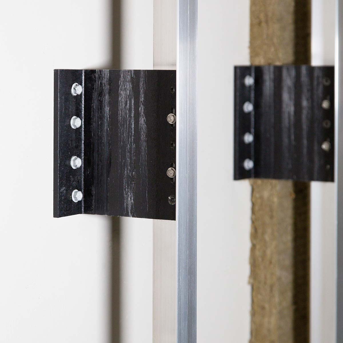
The most critical element to specify as FRP is the wall bracket in the case of a bracket-and-rail system, or the girt itself in the case of a structural “Z” shape. These are available in a variety of depths to match the thickness of the insulation and typically have multiple holes and slotted holes to aid in adjustability. Both horizontal and vertical girts are also available in FRP, but are also available in aluminum or stainless steel. However, if those elements penetrate the insulation layer, the R-Value of the insulation will be de-rated, reducing its effective value.
Photos courtesy of exo Surfaces
Example of FRP bracket and aluminum vertical girts.
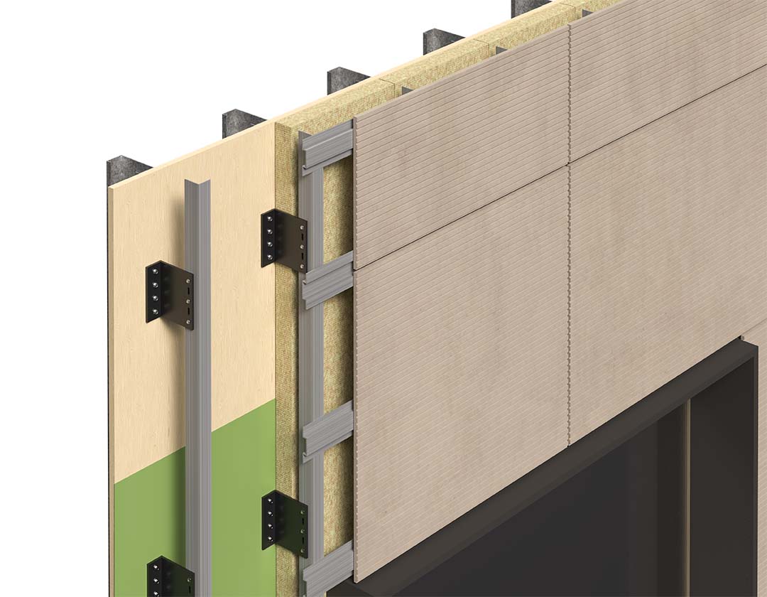
Image courtesy of exo Surfaces
Sub-framing using FRP clip angles or brackets, vertical L girts, horizontal hat channels and concealed panel brackets, back-screwed to cladding panels.
This challenge has been investigated by a number of building science researchers over the years, and there appears to be consensus on how best to accomplish this connection. A detailed study completed by Katarzyna Nowak and Aleksander Byrdy for the Journal of Building Physics in Europe in 2018, which included extensive research and testing, concludes: “The best method for reducing thermal bridges is using ventilated facades on walls made of materials with high thermal resistance and using plastic insulating brackets.”
It is interesting to note that FRP building components have been widely used in Europe for many years and are only now becoming popular in the U.S. While there are currently limited options for recyclability, their performance is well tested in the aerospace and automotive industry and is being selected for critical components due to its strength-to-weight ratio, durability, and low thermal conductivity.
Fire resistance is a critical code compliance and life-safety issue. Compliance is achieved through specific testing and approval processes. The rainscreen assembly does create a continuous, albeit small, cavity through which smoke and fire can travel and even propagate via the “chimney effect.” Generally, fire propagation is not viable when the materials in the cavity are non-combustible, and is substantially reduced when materials in the cavity are self-extinguishing. However, when FRP components are in the cavity, it is wise to consult with the manufacturer of the sub-framing system and the local code authority about testing and compliance requirements.
There are many resources available for architects on both rainscreen assemblies and sub-framing systems and their impact on the thermal properties of the exterior wall. Some recommendations based on the research done for this article that are available online and were not cited earlier include:
- Early Design Tools for Passive House: Estimating Thermal Bridging – Steven Winter Associates, Inc.
- Thermal Performance of Facades by Payette Research and funded by the American Institute of Architects Upjohn Grant
Conclusion
Rainscreen wall framing systems have evolved significantly in the last 25 years. With the key components of drainage, ventilation, and favorable thermal properties, they are an excellent design choice for exterior wall assemblies. The separation of weather barrier from air and moisture barrier in the wall assembly is a winning combination.
With the increased understanding of the impact of thermal breaks, or leaks, and how best to minimize them, we can design better building envelopes. The National Institute of Building Sciences completed a study indicating that the effective treatment of thermal breaks alone can reduce overall energy consumption by up to 20 percent.
Architects have a lot to consider when designing a building. The exterior appearance and creating a building envelope that performs well against multiple metrics are among the most important. While the design of sub-framing systems is most likely not where the design process starts, when it is done effectively, it will result in a successful finish, both inside and outside.
Russell A Davidson, FAIA, served as a volunteer leader of the Architecture profession in numerous roles in the American Institute of Architects, including AIA New York State President and AIA National President. He is a former president and principal of KG+D Architects, an award-winning firm in New York’s Hudson Valley.