Using Building Information Modeling for Architectural Drawings


Using the Model for All Drawings
Part of the mindset of trusting a central model for a project and “building” it as the process moves along is to recognize that the 3-D model is also meant to be the basis for all 3-D views and 2-D drawings. That includes preliminary documents for schematic and design development purposes, renderings and presentation drawings, and ultimately construction documents. Some firms use other software besides BIM as an intermediary to create different drawings for different project phases. The obvious problem with that approach is the loss in efficiency since designs need to be drawn and re-drawn in different computer programs. Even if information is transferred between the two software programs, time is typically spent to verify that important data is transferred properly. Either way, producing drawings multiple times or transferring between programs can increases the risk of errors or omissions.
The better alternative is to select a BIM software program that allows the generation of all needed drawings directly from the central model. Firms that are doing this are benefitting the most since they recognize the full power and potential of BIM as a complete design and documentation tool. By capitalizing on the full capabilities of the software program, they are using it to their advantage to create early design “sketches.” conceptual 3-D views, simple or elaborate renderings, progress prints, and construction documents. This helps such firms achieve their overall management objectives and produce better outcomes.
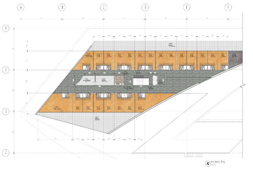
Image courtesy of Vectorworks
BIM information can be taken directly from preliminary models and inserted into working drawings without having to re-draw anything or import a design from another program.
It should be noted that in addition to a core BIM software program, there are also compatible specialty “add-on” programs available. These can be linked in to operate within the main program so that switching in and out of the primary software is not needed, thus saving time and still keeping everything in one place. There are a range of such specialties that may or may not be of interest to a firm so they can be evaluated accordingly. In some cases, a popular add-on may be acquired by the software developer and ultimately be incorporated directly as part of the overall program. That can make it even easier to use and boost the capabilities and accuracy of the software tool.
The People Factor
Any tool is only as good as the capabilities of the people who are using it, of course. In the architectural profession, computer-based design, including BIM, can be done by a variety of people with a variety of experience and skills. In some cases, it is a younger person who may be very adept at using computer technology but doesn’t yet have the experience of how buildings are successfully “put together.” In other cases, it may be a middle-aged or older person who has the design and construction experience but has not advanced their computer skills. In the ideal situation, it is a person who has the knowledge of how to design and construct buildings combined with the skills of using computers to do so. Indeed, many firms, small ones in particular, are achieving great success with experienced and skilled architects designing and managing projects directly in BIM. That means gone are the days of “red-lining” progress prints prepared by a CAD drafter—the designer, project manager, and the drafter can all be one person thanks to the substantial assistance of the computer. That has been a major productivity boost that has allowed many small firms to compete with larger ones on projects they wouldn’t otherwise have the capacity to take on.
Recognizing the variability of capabilities of different people, each firm manager or sole practitioner needs to not only assess the skills and experience of themselves or their people but also be proactive about addressing any shortcomings. Mentoring and balanced work assignments have often been used to effectively help younger professionals get the experience needed to better understand buildings. For computer skills, though, some degree of computer training and practice using the specific program is the common route followed. Even design professionals with good computer skills can benefit from such training to go beyond a basic level of familiarity with the software to a more complete understanding and fully functional level of use. In order to get there, firm principals need to place a value on the training, make it available (i.e., take advantage of in-person, online, or other training options available from software companies, local representatives, or third parties), and cover any nominal cost for it. Typically, firms that invest even a small amount in such training often find a substantial boost in productivity, helping to improve the overall productivity and financial performance of the firm.
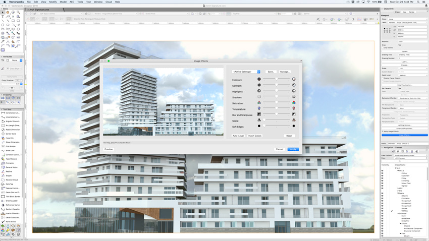
Image courtesy of Vectorworks
Rendered views can be selected to show buildings in simple, sketch-type views, fully photorealistic views with shade and shadow, or anything in between.
Overall, with the proper mindset, the willingness to use BIM as the primary source of information through all phases of a project, and the appropriate level of training and support, BIM can become a means not only to better projects but also to the sustainability and longevity of the firm.
Levels of Development
One of the needed management aspects to address in the process of BIM development and quality control in drawings is the level of detail needed at each stage of design and into construction. Fortunately, there is an organization that is addressing this issue. Known as the BIMForum (www.bimformum.org), it is the not-for-profit United States chapter of buildingSMART International with a mission focused on improved BIM technology, collaboration, education, innovation, and open information exchange. According to the chapter, “Cosponsored by the Associated General Contractors of America (AGC) and the American Institute of Architects (AIA), BIMForum seeks to lead by example and synchronize with counterparts in all sectors of the industry to jointly develop best practices for virtual design and construction.”
A flagship publication of BIMForum is a fully collaborative document known as the Level of Development (LOD) Specification, with it’s latest release in September of 2018.1 Having evolved over several years, this resource is “a reference that enables practitioners in the AEC Industry to specify and articulate with a high level of clarity the content and reliability of building information models (BIMs) at various stages in the design and construction process.” Coordinated with other industry standards, it “defines and illustrates characteristics of model elements of different building systems at different Levels of Development.” Essentially, it defines and standardizes how much detail is expected in a building information model at different stages of the design process. Therefore, if any project team member, including manufacturers, fabricators, or trades, are asked to supply their BIM information, they only need to ask “what Level of Development?” In this way, each person is providing the right amount of information to coordinate with the most current version of the larger computer model for the building.
The LOD Specification is based first on referring to building objects as “Model Elements,” which are eseentially the trade-based components of constructing any building. They are formatted by the familiar Uniformat or Omniclass specification sections (similar to Master Format) used by most spec writers (e.g., Divisions and Sections for sitework, concrete, metals, carpentry, finishes, etc.).2 From there, five levels of detailing are described for each Model Element, identified by the numbers LOD 100, 200, 300, 350, and 400, as described further below.
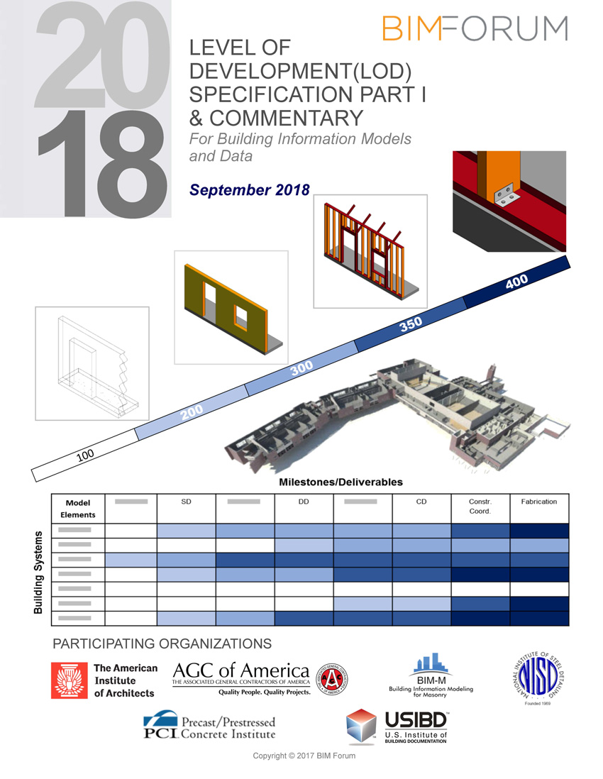
Image courtesy of BIMForum
The Level of Development (LOD) Specification produced by the not-for-profit BIMForum establishes a means for everyone involved in a project to understand the level of detail required at different stages of design.
LOD 100: This is the most basic of models where “the Model Elements may be graphically represented in the Model with a symbol or other generic representation but does not satisfy the requirements for LOD 200. Information related to the Model Element (i.e., cost per square foot, tonnage of HVAC, etc.) can be derived from other Model Elements.” This level of BIM is a starting point showing the existence of a component at a conceptual or schematic level. BIMForum points out that this level does not necessarily provide the shape, size, or precise location of any Model Elements; rather, “any information derived from LOD 100 elements must be considered approximate.”
LOD 200: At this level, basic data is attached to the Model Elements such that they are “graphically represented within the Model as a generic system, object, or assembly with approximate quantities, size, shape, location, and orientation.” As such, everything shown is still fairly generic but can be considered entering the traditional “Design Development” stage. Objects or elements are still considered as approximate “placeholders” in the model.
LOD 300: At this level, things are getting more specific and may be considered as entering the “Construction Documents” level of detail. At this point, the Model Elements are “graphically represented within the Model as a specific system, object, or assembly in terms of quantity, size, shape, location, and orientation.” While it is possible to link non-graphic information at any level (i.e., specification details, cost information, material data, etc.), it is likely to be attached to most Model Elements at this point.
LOD 350: This level is focused on coordination between elements or building systems. In this case, BIMForum comments, “Parts necessary for coordination of the element with nearby or attached elements are modeled. These parts will include such items as supports and connections. The quantity, size, shape, location, and orientation of the element as designed can be measured directly from the model without referring to non-modeled information such as notes or dimension call-outs.” This level of detail is, in essence, complete enough to represent 100 percent “Construction Documents” and a finished, coordinated building in most respects.
LOD 400: This is the full fabrication level equivalent to a shop drawing level of detail. It is worth noting that if trades and fabricators are identified during design so that this level of detail can be incorporated into the model before construction begins, then there will be no need to request or review shop drawings during the construction phase of a project. That creates the best possibility for a fully coordinated design ahead of time and can make a firm more efficient during the construction phase.
By using these standardized Level of Development, all design and construction professionals can proceed in an orderly sequence to provide the appropriate information, receive coordination feedback, and then move on accordingly to the next level.
Notice


