Designing Modern Wood Schools


Structural Design
Schools offer unique design challenges, in part because of the great variety of spaces. Requirements include a mix of smaller spaces such as classrooms, offices, corridors, and bathrooms; medium spaces such as choir rooms and labs; and large spaces such as gyms, cafeterias, and libraries.
Although a detailed discussion of structural design options is beyond the scope of this course, this section will consider typical school requirements and demonstrate how they can be met with wood-frame construction, while at the same time reducing costs.
Many schools include long, rectangular classroom wings, separated from the gym and cafeteria, with classes that feed into a corridor from both sides. Classrooms are typically 800 to 1,100 square feet, sized to accommodate 20 to 30 students, and are square to slightly rectangular. Common classroom sizes include 28 by 30 feet, 30 by 30 feet, and 32 by 32 feet, while corridors tend to be 6 to 18 feet wide. Minimum ceiling height is typically 9 feet, with a floor-to-floor height of about 13 feet.
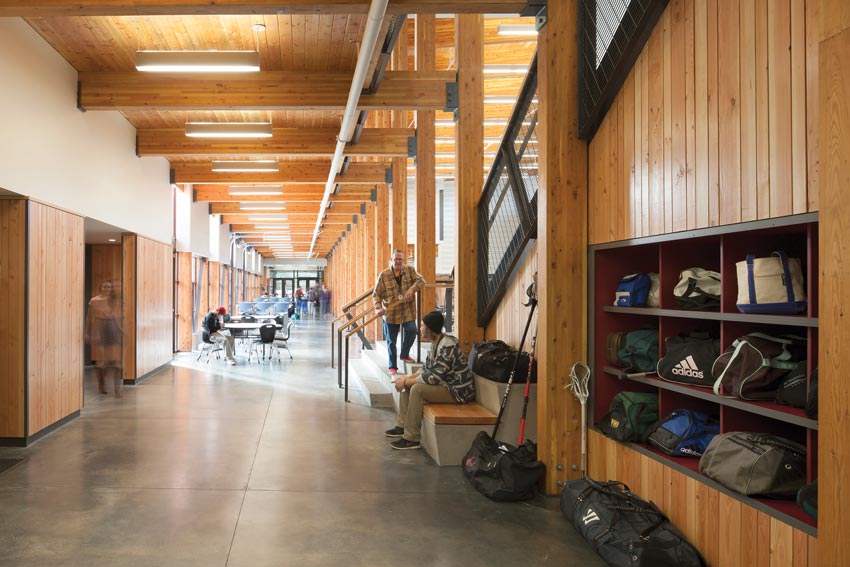
Photo: Lara Swimmer
Location: Vashon Island, Washington
Architect and Engineer: Integrus Architecture
Typical school corridors range from 6 to 18 feet. At this 84,000-square-foot, Type V school, dimension lumber, glulam, and light-frame trusses were used for the structure, reflecting the community’s values and desire to promote thoughtful stewardship of natural resources.
Structural Loads
An important aspect of the IBC is that it is scaled to reflect risk. Per IBC Table 1604.5, buildings are classified into risk categories based on use, from Risk Category I for those representing a low hazard to human life in the event of failure (such as storage buildings) to Risk Category IV for structures with greater consequences associated with their failure (such as hospitals). They are further defined based on the likelihood of a specific type of event occurring. Buildings constructed in regions known for hazards, such as hurricanes, earthquakes, or floods, are subject to design requirements that make them better able to withstand these events.
Educational facilities are generally Risk Category III and must be designed for structural loads that are 10 to 25 percent higher than buildings in lower risk categories. Common loadings include:
- Classroom floor live load = 40 pounds per square foot (psf)
- Corridor floor live load = 80 to 100 psf
This is where the relative light weight of wood-frame systems can be a cost advantage. Even a floor system detailed to meet objectives for fire resistance and acoustics—with gypsum wallboard, lightweight concrete topping, resilient channels, and insulation—results in a floor dead load of just 25 to 35 psf. For comparison, a structural steel system with cast-in-place concrete or a precast concrete slab would likely be twice that amount.7 Wood’s light weight also has potential benefits in terms of foundation and seismic requirements (seismic force is relative to weight), which add to the savings.
It should be noted that the IBC allows reduced loads in certain cases that are relevant to school design. Where members are used to support a large surface of floor area, the code recognizes the unlikelihood that the entire area will be loaded to its maximum all the time. Per ASCE 7-16: Minimum Design Loads for Buildings and Other Structures, Section 4.7.2, exterior and interior columns and beams in spaces that meet minimum tributary area requirements may be designed for lower live loads. In a 32-by-32-foot classroom, for example, a column in the exterior wall can be designed for 23 psf live load instead of the standard 40 psf.
Floor Framing
Wood framing is a viable choice for floor spans of 25 to 32 feet, which are typical of classrooms. It can meet the same safety and performance requirements, and follow essentially the same grid design as other materials, but often at much less cost. While savings vary by city, cost estimates performed by EQS Consultants based on RS Means data for 2016 Q2 indicated that, compared to steel and concrete, wood-frame floor systems offer the following savings based on a 32-by-32-foot grid:
- Orlando, Florida: $4/square foot
- Los Angeles: $4/square foot
- Washington, D.C.: $3/square foot
- Houston: $3/square foot
- Charlotte, North Carolina: $2/square foot
- San Francisco: $2/square foot
Options for classroom floor assemblies include I-joists and parallel chord trusses. (Dimension lumber is suitable for the smaller spans needed for corridor assemblies.) As shown in Figure 7, the required wood member sizes for a standard classroom design are similar to steel. The table is shown over a typical grid that includes columns in the exterior walls and corridor walls, all directly aligned with classroom separation walls.
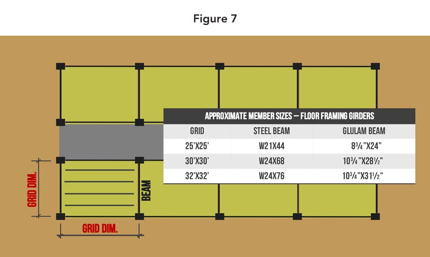
Source: WoodWorks
Assumptions: Live load = 40 psf, wood dead load = 30 psf, steel dead load = 70 psf. Sizes shown are for illustration purposes. All member sizes should be provided by a project’s structural engineer.
While Figure 7 indicates that the glulam beams are typically 3 to 71/2 inches deeper than the steel beams, this difference could be 21/2 inches smaller than the beam depths would indicate. This is because the common steel option is an open-web joist, which includes a joist seat that drops the beam by about 21/2 inches. Glulam beams can be flushed to the top of the I-joist or truss, and a top flange hanger can be used to support the truss or joist from the beam.
Although the typical grid shown in Figure 7 can be accommodated with wood framing, taking a slightly different approach can reduce costs even further. For example:
- A designer may choose not to align columns in the exterior and corridor walls with the classroom separation walls, but rather shorten the floor spans by using a column spacing (along the corridor and exterior walls) of 20 to 24 feet. Although this would likely add an additional row of columns and beams, it would reduce their size and provide shallower floor joist members, allowing more room for mechanical, electrical, and plumbing in a dropped ceiling application. Column locations would need to be coordinated with openings in the exterior and corridor walls.
- By using wood-frame corridor walls and exterior walls as bearing walls, columns and beams could be eliminated. (See Wall Framing below.)
Although not a code criteria, floor design is often governed by vibration at the span ranges above, regardless of material. Options for floor vibration analysis include the use of higher deflection criteria to add stiffness (e.g., L/480 or L/600 instead of L/360 for live load), and proprietary assemblies that have been tested and rated for vibration. A research organization, FPInnovations, has also devised a method for evaluating complete floor systems (including solid sawn joists, I-joists, parallel chord trusses, sheathing, toppings, etc.) and calculating vibration performance.
AN EFFECTIVE CHOICE FOR STUDENT HOUSING
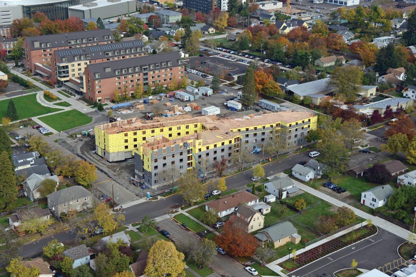
Photo: Walsh Construction Company
UNIVERSITY OF OREGON RESIDENCE HALL
Location: Eugene, Oregon
Architect: Mahlum
Structural Engineers: Froelich Engineers
When Mahlum Architects won the bid to design a new 140,000-square-foot, 530-bed student residence hall at the University of Oregon, the university directed the design team to use wood-frame construction.
“We have seen a very strong trend toward the use of wood in student housing as a way to reduce costs for this project type and at this scale,” says Beth Brett, project manager for Mahlum, which also designed a major wood-frame housing project for the University of Washington. “This has been a typical approach for some time in developer-led multifamily projects. Now, with the rising cost of construction, universities have been looking to this approach to help manage their project budgets.”
The University of Oregon project required unique responses toward important neighboring buildings. To the north, the Many Nations Longhouse required unobstructed solar access on the winter solstice to their ‘Expression Place.’ Mahlum modeled the sun’s path to ensure the building’s unique form did not cast shadows on this ceremonial zone. To the west and east of the building, landscape areas help break down the building massing to ease the transition between institutional and residential scales. Through these and other design features, the new residence hall enhances the university’s commitment to live/learn communities by co-locating a lecture hall, seminar room, and study spaces with an open lounge and kitchen and a maker-hacker space.
Notice