Designing for Earthquakes


Wood-Frame Seismic Force-Resisting Systems
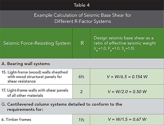
Specific wood-frame seismic force-resisting systems recognized in ASCE 7 are listed in Table 3. In accordance with ASCE 7, each seismic force-resisting system is associated with seismic design coefficients (R, Cd and Ωo) and height limitations based on seismic design category (SDC). For wood-frame seismic force-resisting systems, listed seismic design coefficients are applicable for systems designed in accordance with the SDPWS for wood-frame shear walls and diaphragms and with the NDS for wood member and connection design. In typical wood-frame platform construction, the bearing wall system category is generally applicable because shear walls used for seismic force resistance also function to support gravity loads of the building. While slightly larger R-factors are associated with shear walls in building frame systems in which gravity loads are carried by a separate structural system (such as a structural frame of beams and columns) and the shear walls resist seismic shear loading only, this type of structural system is less prevalent than standard platform construction. The slight increase in R-factor recognized for building frame systems is based largely on the judgment that the shear walls providing shear resistance in such systems are less susceptible to strength and stiffness degradation from combined gravity and seismic shear loading than shear walls in bearing wall systems.
As defined in ASCE 7-10, the most common seismic force-resisting systems employed in wood-frame platform construction are A15 and A17. The design requirements and construction details for wood-frame shear walls used in those systems for seismic force resistance are contained in the SDPWS. Specific details for each system include the following:
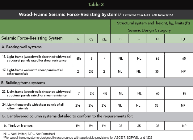
SDPWS 4.3: Wood-frame wood structural panel shear walls (applicable for bearing wall system A15 and building frame system B22 per ASCE 7-10)
▶ This system includes wood structural panels conforming to the requirements of the U.S. Department of Commerce/National Institute of Standards and Technology documents, PS 1-09 Structural Plywood or PS 2-10 Performance Standard for Wood-Based Structural-Use Panels.
▶ All framing members and blocking are 2-in. nominal or greater except that 3-in. nominal or greater framing is used at adjoining panel edges for closely spaced nails, larger-diameter nails or higher-strength shear walls.
▶ Nails are located at least 3/8 in. from panel edges and fastener spacing at panel edges is not less than 2 in. on center (o.c.).
▶ Foundation anchor bolts have a steel plate washer under each nut not less than 0.229 in. x 3 in. x 3 in. in size except where standard cut washers are explicitly permitted.
▶ Design for shear and overturning provides for properly sized tension and compression chords and shear and overturning anchorage.
▶ Maximum shear wall aspect ratio (e.g., height-to-length ratio) is 3.5:1.
▶ Allowable unit shear strengths range from 200 plf (3/8-in. rated sheathing on one side, 6d common nails and 6 in. o.c. nail spacing at panel edges) to 1,740 plf (19/32-in. rated sheathing on two sides, 10d common nails and 2 in. o.c. nail spacing at panel edges).
▶ This system is permitted in seismic design categories A, B, C, D, E and F.
Source: FEMA (2006). Homebuilders’ guide to earthquake-resistant design and construction, FEMA 232, Federal Emergency Management Agency, Washington, D.C.
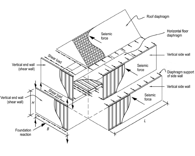
LOAD PATH IN LIGHT-FRAME WOOD BUILDING
This Figure illustrates the load paths for resistance to seismic forces. When structural panels such as plywood or oriented strand board (OSB) are properly attached to lumber floor, roof and wall framing, they form diaphragms and shear walls that are exceptional at resisting these forces.
SDPWS 4.3: Wood-frame shear walls sheathed with other materials (applicable for bearing wall systems A17 and building frame system B24 per ASCE 7-10)
▶ This system includes shear panels of particleboard, structural fiberboard, gypsum wallboard, gypsum base for veneer plaster, water-resistant gypsum backing board, gypsum sheathing board, gypsum lath and plaster, and Portland cement plaster, or lumber sheathing with fastening and shear wall aspect ratio varying by shear panel type.
▶ All framing members and blocking used for shear wall construction are 2-in. nominal or greater.
▶ Foundation anchor bolts have a steel plate washer under each nut not less than 0.229 in. x 3 in. x 3 in. in size except in some cases where standard cut washers are explicitly permitted.
▶ Design for shear and overturning provides for properly sized tension and compression chords and shear and overturning anchorage.
▶ Allowable unit shear strengths span a wide range across different sheathing materials. For 1/2-in. gypsum wallboard, allowable unit shear strengths range from 75 plf (sheathed on one side, unblocked panel edges, and 7-in. fastener spacing at panel edges) to 360 plf (sheathed on two sides, blocked panel edges, and 4-in. fastener spacing at panel edges). Particleboard, structural fiberboard, horizontal lumber and vertical board shear walls are permitted in seismic design categories A, B and C.
▶ Gypsum wallboard, gypsum base for veneer plaster, water-resistant gypsum backing board, gypsum sheathing board, gypsum lath and plaster, or Portland cement plaster, and diagonal lumber shear walls are permitted in seismic design categories A, B, C and D.
Wood-frame wood structural panel shear walls are prevalent in high seismic areas where lateral forces from seismic loading control the required length of shear walls. Relatively large design strengths and permitted use of up to 3.5:1 aspect ratio wood structural panel shear walls provide design flexibility to accommodate building configurations where total length of wall or aspect ratio of wall portions available for seismic force resistance is limited. Additionally, wood-frame wood structural panel shear walls are permitted for use in all SDCs and, in SDC D, E and F, are permitted with structural height of 65 ft. In contrast, wood-frame shear walls sheathed with other materials are generally associated with smaller values of design strength, most commonly used where large lengths of shear wall are available, not permitted in SDC E and F, and limited to a structural height of 35 ft in SDC D. In some cases, such as for structural fiberboard shear walls and particleboard shear walls, use of such shear walls for seismic force resistance is limited to SDC A, B and C only with a structural height of 35 ft in SDC C.
Anchorage of Concrete or Masonry Structural Walls to Wood Diaphragms
Although special design criteria for anchorage of concrete or masonry structural walls to wood diaphragms have been in place for decades, some designers are unaware of these requirements. In fact, they exist both in ASCE 7 and building codes, having been developed to address instances where tall, single-story concrete and masonry structural walls became detached from supporting roofs, resulting in collapse of walls and supported bays of framing. The intent is to prevent the diaphragm from tearing apart during strong shaking by requiring transfer of wall anchorage forces across the complete depth of the diaphragm.
These special criteria, which are applicable in Seismic Design Categories C, D, E and F, include designing concrete or masonry structural wall anchorage to wood diaphragms for forces in accordance with ASCE 7 Section 12.11.2 and additional criteria for seismic detailing for transfer of anchorage force that includes:
• Use of continuous ties between diaphragm chords to distribute concrete or masonry structural wall anchorage forces into the diaphragm
• Permitted use of sub-diaphragms to transmit concrete or masonry structural wall anchorage forces to main continuous cross-ties
• Restriction on use of toe-nailed connections and nails subject to withdrawal for transfer of concrete or masonry structural wall anchorage forces
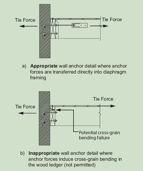
• Restriction on use of framing loaded in cross-grain bending or cross-grain tension
Details commonly employed for transfer of wall anchorage forces into the diaphragm use mechanical attachment between the wall anchor and wood framing oriented perpendicular to the wall (Figure C4.1.5B), avoiding direct loading of wood framing in cross grain bending. Special detailing provisions for wood diaphragms consistent with those in ASCE 7 have been added to 2015 SDPWS in Section 4.1.5.
For inverted pendulum structures of timber frames (e.g., system G6. Timber Frames), seismic design coefficients (R=1.5, Ωo=1.5, and Cd=1.5) are applicable. Such systems include wood pile-supported structures where the wood member and its connections are designed in accordance with member and connection provisions of the NDS.
Seismic Design Category
The seismic design category for the structure at the site is critical for proper application of requirements for seismic design. The SDC is used as a trigger for permitted use of seismic systems and structural height limitations as seen in Table 3. It is also used to trigger applicability of special requirements associated with structural redundancy and structural irregularities in the building system. SDC is determined based on several factors:
▶ Soil properties at the site, or site class, which range through site class A, B, C, D, E and F. Site class A is associated with presence of hard rock. Site class F is associated with peats and/or highly organic clays, very high plasticity clays and very thick soft/medium stiff clays.
▶ Mapped values of seismic hazard
▶ Risk category of the structure
For short-period structures, such as most wood-frame structures, ASCE 7 allows determination of the seismic design category based on value of SDS and risk category alone (see Table 5) provided alternative criteria are met for structure period and diaphragm flexibility and for sites where mapped values of S1 are less than 0.75. Seismic design categories A, B, C, D, E and F reflect the range of possible categories under ASCE 7. They are similar to seismic zones found in previous codes; however, seismic design categories are more representative of the risk to a particular building because they incorporate the structure’s risk category, site conditions and mapped seismic hazard at the site.
SDC A represents a very low seismic hazard for which there are no seismic-specific limits on structural height, system type, structural redundancy or structural irregularities. Structures located in this category are not subject to design forces determined in accordance with the ELF. Beginning with SDC B, seismic forces in accordance with ELF are applicable and consideration must be given to special requirements for structural irregularities. Special requirements and limitations become increasingly significant beginning in SDC C. As can be seen in Table 3, as seismic design category increases, structural height limitations apply as well as limitations on the use of particular systems.
Notice