Duct Installation and Testing


One Simple Test to Discover Restrictive Duct Systems
Duct systems are a critical system is often overlooked
It’s tough to talk with a customer about the poor shape of their duct system. Unfortunately, it’s the part of an HVAC system that most homeowners don’t consider, yet it determines how well their equipment works.
What if there were a quick and simple test that made this conversation easier? What if it can also help you discover airflow issues before you inherit them? Interested? Let’s look at a duct pressure test that can get you and your customers on the same page regarding their duct system and its importance.
You can confirm a restrictive duct system in less than 30 seconds with a single pressure test.
Test Instruments and Accessories
Before you can measure duct pressures, you need a pressure testing kit that includes:
- Manometer — analog or digital
- Static pressure tips and tubing — neoprene or silicone
- 3/8-inch test port plugs
- Small drill/impact gun with a step bit or 3/8-inch drill bit with a sheath/stop
- Scratch awl — for cleaning out internal duct liner/insulation
- Carrying case for all your goodies.
You can typically put together a complete kit for around $200. Don’t skip on purchasing any of these items; they each have a purpose.
Find the Maximum Rated TESP
Before you begin to use your test instruments, find the air handling equipment nameplate. It has important information you’ll need. Air handler and package unit nameplates are often on the blower panel. You’ll have to look a little harder for a gas furnace nameplate. It’s inside the burner compartment.
Each nameplate has a maximum rated total external static pressure (TESP). The standard rating for most residential systems is .50 inches w.c. (inches of water column). However, other pressure ratings range from .30 up to 1.0, so look carefully.
Once you locate this rating, write it down. You will soon need it to determine a number to compare your measured duct pressures against.
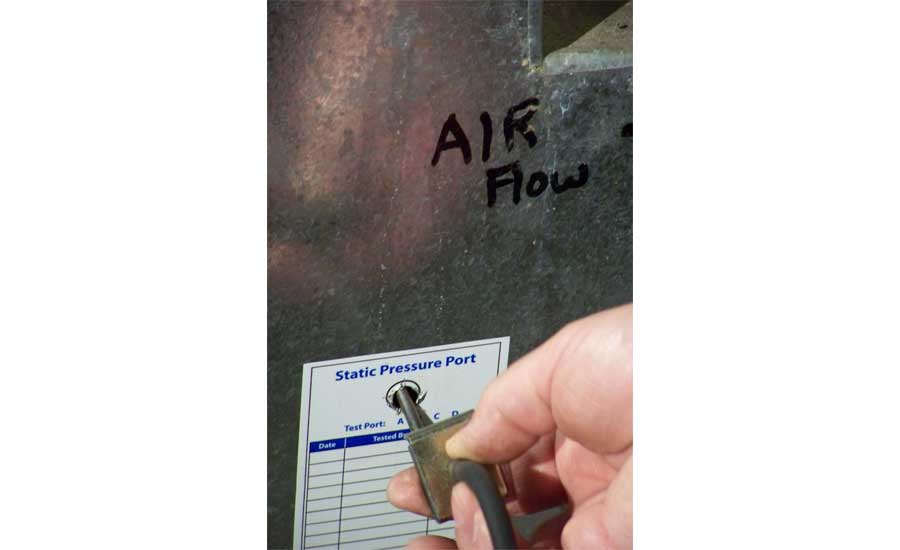
Install Duct System Test Ports
Next, you need to install test ports in the return and supply ducts. The most common locations are in the return and supply plenums where air enters and exits the equipment.
Once you locate suitable test sites, drill a 3/8-inch hole into the supply and return plenums. When testing metal duct systems, use a drill bit with a stop to prevent it from penetrating too far into the duct. If you test fiberglass duct board, you can use a scratch awl to install the test ports. If possible, measure at least 2 feet away from the fan discharge to avoid turbulence and inaccurate pressures.
Whenever you do a duct pressure test, I recommend you use the phrase “installing test ports.” Don’t tell a homeowner you plan to drill holes in their system. Despite your best intentions, they don’t want you to drill holes in their HVAC system. It might not seem like much, but that slight phrase change can make a big difference.
Measure Duct System Pressures
Now it’s time to measure duct pressures. Connect one end of the pressure tubing to the static pressure tip. Next, connect the opposite end of the tubing to the manometer port.
Know your manometer. Some styles have a negative (-) and positive (+) port that affects where your hose connects. Supply ducts are positive pressure, while return ducts are negative. If you use an analog manometer, place it on a level surface and adjust it to zero before you take any measurements.
Next, adjust the thermostat so the blower runs on its highest speed. Insert the static pressure tip into the return duct test port and record the pressure reading from your manometer. Remove the static pressure tip from the return duct and insert it into the supply duct test port. Record the supply duct pressure reading from the manometer.
Let’s say you test a gas furnace and condensing unit. You measure duct pressures and record .30 inches w.c. in the return duct and .07 inches w.c. in the supply duct. At first glance, these pressures don’t mean a lot. However, once you have a number to compare them against, they reveal much more.
Diagnose Duct System Pressures
Once you measure duct system pressures, you can compare them to something called a pressure budget. Pressure budgets help you find out how restrictive the ducts are to airflow. Remember the maximum rated TESP that you wrote down earlier? Use that number to create your duct system pressure budgets.
Here is how they work: NCI has found that well-performing duct systems often run less than 40 percent of the air handling equipment’s maximum rated TESP. Since there are two sides to a duct system (return and supply) you need to divide this pressure in half. As a result, the return duct pressure shouldn’t exceed 20 percent of the maximum rated TESP. Also, the supply duct pressure shouldn’t exceed 20 percent of the maximum rated TESP.
As an example, let’s say the nameplate rating is .50 inches w.c. To get your return duct and supply duct pressure budgets, multiply .50 times 20 percent (.50 x 20 percent = .10). Use this target to compare against your duct pressure measurements. Ideally, you don’t want your return or supply duct pressures to exceed .10. The side of the duct system that exceeds this pressure the most is where the greatest airflow restrictions hide.
Since you already have duct pressure measurements from the previous step, you can see the most restrictive side of the duct system. The return duct pressure was .30 inches w.c. and supply duct pressure was .07 inches w.c. When you compare these readings to the .10 inches w.c. pressure budget, you can see the return duct pressure is three times higher.
As you investigate, you will find restrictions somewhere in the return duct system. Look for sharp duct fittings, poorly installed flexible ducts, undersized return ducts, or something blocking off the floor return grille.
You also can see that the supply duct pressures are lower than .10 inches w.c. You may think that’s a great sign. It might be. However, keep looking to be sure.
Low Duct System Pressures
When duct pressures look too good to be true, they probably are — especially if one side of the duct system is in terrible shape. When you encounter low pressure on one side of the duct system, check for duct leakage and/or disconnected ducts.
You will also encounter times when both sides of the duct system have low duct pressures. If you find this, perform a visual equipment inspection. A dirty blower wheel moves less airflow and leads to reduced pressures.
Another source of low duct pressure is when a variable-speed air handler runs in the “fan on” position. The blower operates at approximately 50 percent of programmed airflow in this position. Once the fan ramps up to 100 percent airflow, duct pressures increase.
Keep Duct Pressures in Context
While duct pressures are a simple way to identify duct restrictions, they have limitations. One drawback is how they react to changes in airflow. As airflow decreases, so will the duct pressures. This is one reason it’s a good idea to gather additional pressure readings if you’re in doubt.
Sometimes you need to incorporate additional tests to further diagnose airflow problems. However, duct pressures are a great first step to look beyond the equipment. Remember, the duct system determines true HVAC system efficiency. Duct pressures give you a small glimpse into how much of an impact they truly have.
David Richardson, serves the HVAC industry as a curriculum developer and trainer at National Comfort Institute, Inc. (NCI). NCI specializes in training that focuses on improving, measuring, and verifying HVAC and Building Performance.
Notice