Understanding the Critical Elements of Air & Vapor Barriers


Wall System Constructions
Placement of certain components within a wall assembly, combined with the geography of where the project is located, will affect your determination of what the ideal wall assembly for the job should be.
One factor to keep in mind is dew point—the temperature at which air is saturated with water vapor, causing vapor to change from a gas to a liquid. When air has reached the dew-point temperature at a particular pressure, the water vapor in the air is in equilibrium with liquid water, meaning water vapor is condensing at the same rate at which liquid water is evaporating. One of the main elements that affects where the dew point develops is the insulation. As a result, the position of the insulation influences where the dew point develops within a wall assembly.
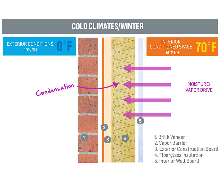
Vapor drive from warm air in the building could create condensation within the insulation depending on the R-value and dew point location.
Will this wall construction work? Why or why not?
You may note that a non-permeable membrane has been placed on the exterior sheathing in conjunction with the use of batt insulation in the interior stud cavity. As a result, this wall will not perform well. The warm, conditioned air on the interior will drive outward to try to balance with the cold exterior air, but because a non-permeable membrane (the vapor barrier designated by the orange line) is present, the vapor will get trapped in the insulation and collect—not a good thing.
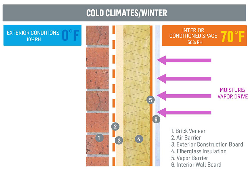
Warm, conditioned air is kept inside the building without collecting in the insulation, and vapor from the outside can enter and exit the assembly through the permeable membrane.
How about this wall? Will it perform well? Why or why not?
All conditions are the same as in the previous example except we moved the non-permeable membrane to the interior of the wall and placed a permeable membrane against the exterior sheathing. The warm, conditioned air is stopped before it can reach the insulation and collect. Exterior conditions will change as the climate changes from cold to warm, and moisture vapor will be permitted to enter the assembly because we have a permeable membrane on exterior sheathing. Moisture that enters the wall assembly will be allowed to exit because of the permeable membrane. This is considered a “good wall” or “permeable wall.”
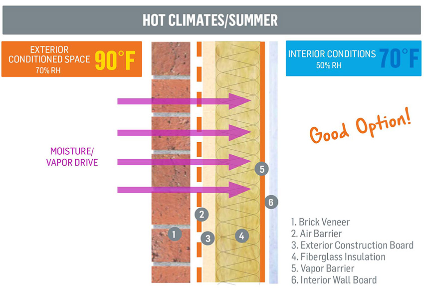
This type of double-barrier assembly is a good option for hot climates as it keeps hot, moist air out, but allows the wall to “breathe.”
This same wall construction works well in hot climates. It is worth noting, though, that this wall performs on paper and, if a modeling program was run with this wall, it would perform well. There are a few things to consider regarding this wall type, however that may not be apparent from the diagram. The vapor barrier that is present on the interior stud cavity is a loose mechanically fastened piece of polyethylene. The material is attached with numerous fasteners resulting in many penetrations in addition to penetrations coming from electrical outlets, pipe penetrations and the like. This will compromise the performance and functionality of the vapor barrier in this example. Additionally, on multiple level constructions, the polyethylene starts and stops at every floor, making it very difficult to detail and tie in correctly. These are the sort of challenges that you will encounter in real-world applications, but may not always foresee without careful analysis of the potential variables.
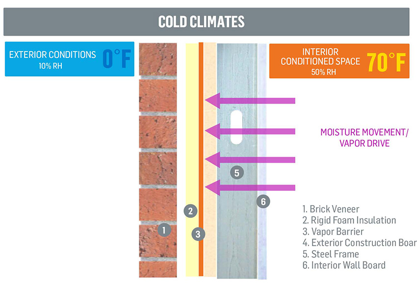
Rigid insulation is placed in the exterior cavity, and a vapor barrier keeps moisture vapor from escaping the building without allowing condensation.
Let’s look at a different wall system construction. Will this wall assembly perform well?
In this wall assembly example, the insulation is in the form of rigid insulation. There is no batt insulation in the interior stud cavity. The warm conditioned interior air tries to drive outward to the cold exterior air, but it is restricted by a fully adhered air and vapor barrier. With the absence of batt insulation in the stud cavity, there is nothing on which the moisture can collect and compromise the integrity of the wall. Steel studs and exterior sheathing also have a much better tolerance to moisture until conditions change and drying can occur.
This wall has been labeled “the perfect wall.” The placement of the rigid insulation in the exterior cavity conditions the exterior space while pushing the dew point to the exterior cavity as well. This ensures that any moisture that accumulates as the result of the dew point will occur in the exterior cavity. It will then be able to exit out a weep system in the brick veneer. The installation of the air and vapor barrier on the exterior sheathing helps ensure a quality installation because it can be easily inspected from outside the building. With rigid insulation located in the exterior cavity, this wall also satisfies the International Energy Conservation Code (IECC) requirements for continuous insulation.
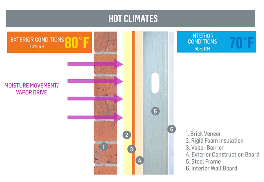
The “perfect wall” is not only perfect in cold temperatures, but performs strongly in hot climates, too.
If we were to deploy this “perfect wall” in a hot climate, we would see the warm, humid air driving toward the interior cool, conditioned air. With the presence of rigid insulation against a fully adhered air and vapor barrier membrane, the warm humid air is prevented from entering and meeting the cool conditioned air. The “perfect wall,” when designed and installed correctly, works in any climate and any geographical location.
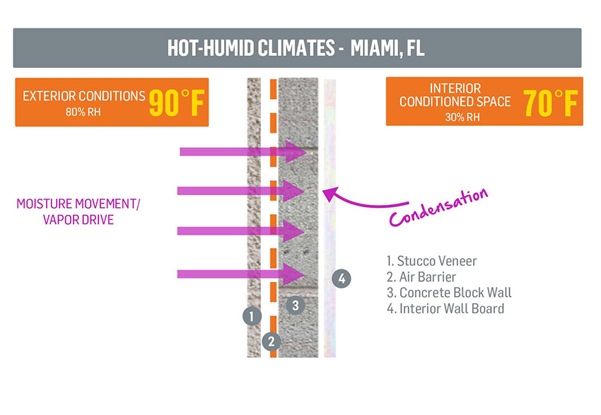
Moisture permeates the air barrier, then collects on the concrete wall where it cannot dry due to the high humidity.
Now let’s factor in a more specific climate consideration. Will this wall work in a hot, humid climate, like one might find in Florida?
This is a common wall assembly in the extreme southern geography of the U.S., e.g., Miami. A permeable membrane is applied to the exterior face of the block, but when the climate is continuously hot and humid, this construction will not perform well. The hot, humid air will drive to reach the cool, dry interior air and will bring a tremendous amount of vapor with it, causing moisture collection in the interior space. In climates where there is little variation in temperature, there is little to no opportunity for the wall to dry out. This is an example of where a permeable membrane is not the best option.
A better option would be this same construction, but with an impermeable vapor barrier instead of the air barrier. Hot humid air will be prevented from driving inward from a fully adhered air and vapor barrier. This keeps the outside air and interior air separated, and eliminates the possibility of condensation within the wall.
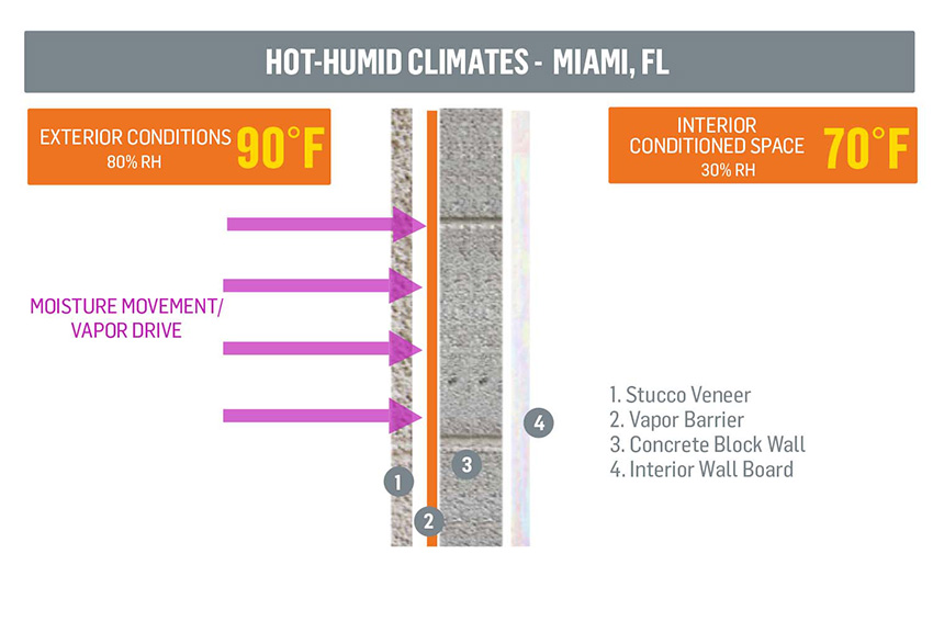
Moisture permeates the air barrier, then collects on the concrete wall where it cannot dry due to the high humidity.
Now let’s consider a wall assembly example in a climate where there are no extreme changes between the outside and inside air characteristics. In this scenario, either a permeable or non-permeable membrane will perform well. The struggle of hot, humid air driving to cool, conditioned air is not present. There will only be minor swings in temperatures, so any moisture that develops will have an opportunity to dry once the temperatures return to a consistent level.
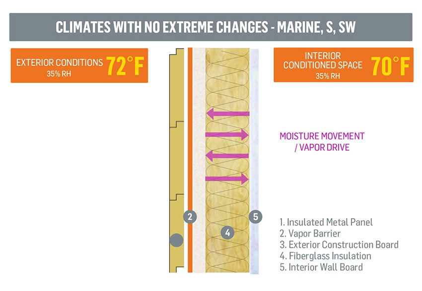
An impermeable vapor barrier will be more successful in keeping out water vapor that has a hard time drying in humid climates.
Notice


