Cross Laminated Timber


Mechanical fasteners may be dowel-type (e.g., nails, screws, glulam rivets, dowels, bolts) or bearing-type (e.g., split rings, shear plates).
CLT connections should adhere to the NDS just like other wood connections. The NDS has specific provisions for commodity fasteners, which can be found in Appendix K - L. It does not yet include information on how to apply its dowel bearing equations regarding grain direction to CLT. However, the existing NDS design provisions can be applied with some modification, assuming that the CLT dowel bearing strength is based on the species-specific gravity of the ply in the shear-plane and the loading direction relative to the grain angle of the ply in the shear-plane. A reduction in effective thickness is also taken for the plies running perpendicular-to-grain if the ply in the shear-plain is parallel-to-grain.
Self-tapping screws will likely be the most common connector used in CLT construction. These are proprietary connectors and design values and requirements would be specified by the manufacturer. The manufacturer will be responsible for providing lateral and withdrawal connection values and any information needed to explain how to apply provisions of the NDS (e.g., dowel bearing strength adjustments, dowel bending strengths of the self-tapping screws, and specific application of the NDS yield equations).
Design values for proprietary fasteners and information on their approved use are available in Evaluation Reports or the manufacturer's literature.
Researchers in Europe have developed design procedures for traditional connections in CLT. These include dowels, wood screws, and nails, which are commonly used in Europe for designing CLT assemblies. Empirically-based equations were developed for the calculation of characteristic embedment properties of each type of fastener (i.e., dowels, screws, nails), depending on the location with respect to the plane of the panel (perpendicular to or on edge). Those equations were verified with testing and results seem to correspond well with calculated predictions.16
Yield mode equations were adopted for the design using CLT fastener embedment strength equations. Empirical equations have also been developed for the calculation of the withdrawal resistance of the various types of fasteners in CLT based on hundreds of tests. Based on limited exploratory validation tests conducted at FPInnovations using self-tapping screws on European CLT, the proposed embedment equations seem to provide reasonable predictions of both the lateral and withdrawal capacity based on the Canadian timber design provisions.17 More work is needed, however, to validate the proposed equations using North American made CLT and different types of fasteners.
Due to the reinforcing effect of cross-lamination in CLT, it is speculated that current minimum geometric requirements given in the NDS for dowels, screws and nails in solid timber or glulam could be applicable to CLT. However, designers need to be cautious about this as further verification is needed, considering the specific features of individual panel types. Brittle failure modes, which have not yet been investigated, also need to be taken into account.
The Connections chapter in the U.S. CLT Handbook is mainly focused on connecting CLT to CLT. However, since all buildings are considered to be mixed construction to a certain extent, the scope covers hybrid construction, where traditional wood-based systems (e.g., light frame, glulam, etc.) or materials such as concrete or steel are mixed with CLT to resist vertical and lateral loads.
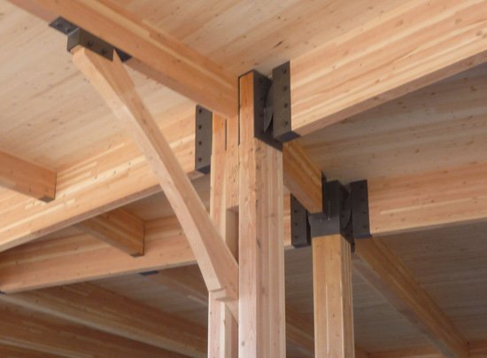 |
With virtually no square angles in the structure, beam-to-column connections created a challenge. To avoid the need for more than a hundred different configurations, the team designed a steel pin connector which allowed most joints throughout the project to have elegant and typical connections. Photo courtesy of Uihlein/Wilson Architects |
Vibration Performance of Floors
Studies at FPInnovations found that bare CLT floor systems differ from traditional lightweight wood joisted floors with typical mass around 4 pounds per square foot (20 kilograms per square meter) and fundamental natural frequency above 15 Hz, and heavy concrete slab floors with a mass above 40 pounds per square foot (200 kilograms per square meter) and fundamental natural frequency below 9 Hz. Based on FPInnovations' test results, bare CLT floors were found to have mass varying from approximately 6 pounds per square foot (30 kilograms per square meter) to 30 pounds per square foot (150 kilograms per square meter), and a fundamental natural frequency above 9 Hz. Due to these special properties, the standard vibration controlled design methods for lightweight and heavy floors may not be applicable for CLT bare floors.
Some CLT manufacturers have recommended that deflection under a uniformly distributed load (UDL) be used to control floor vibration. Using this approach, the success in avoiding excessive vibrations in CLT floors relies mostly on the designer's judgment. Besides, static deflection criteria can only be used as an indirect control method because they ignore the influence of mass characteristics of the floors. Therefore, a new design methodology is needed to determine the vibration controlled spans for CLT floors. A proposed design methodology for controlling vibrations of CLT floors under normal walking is given in Chapter 7 of the U.S. CLT Handbook.
Notice


