Code-Compliance Conflicts in the Exterior Wall Assembly


THE CODE CHALLENGE
While the variety of functionalities and the different components and systems that must be integrated into the building envelope make for a complex specification, perhaps the most challenging aspect of designing a code-compliant exterior wall system is deciphering the applicable codes themselves. There are many building codes that weigh in on one aspect of the building envelope or another, and they regularly reference other building codes as they describe their prescriptive and alternative compliance paths. When it comes to defining the design requirements of a building enclosure, no single code is self-contained and comprehensive.
Photo courtesy of Laminators Incorporated
Perhaps the most challenging aspect of designing a code-compliant exterior wall system is deciphering the applicable codes themselves.
Intertwined Code Requirements
In order to design a code-compliant building envelope, a designer must satisfy provisions in multiple codes, while navigating the intertwined references and conflicting requirements. Here is a high-level explanation of the current entanglement of the codes defining a safe and acceptable building enclosure.
The International Building Code (IBC) is the model code that defines safe building and design practices, and it has been adopted, in one version or another, throughout the United States. There are many sections of the IBC that apply to the design and functionality of exterior walls. Chapter 14: Exterior Walls establishes minimum requirements for exterior walls in terms of moisture control, fire resistance, and structural support. It defines design and compliance measures for many specific materials used for exterior wall construction. It requires that exterior walls be designed to resist superimposed loads, as required by Chapter 16: Structural Design of the IBC, and meet the fire-resistance ratings, as required by Chapter 7: Fire and Smoke Protection Features of the IBC, if required. Chapter 14 also requires that certain exterior wall assemblies be tested in accordance with and in compliance with the acceptance criteria of the National Fire Protection Association (NFPA) 285 test standard, Standard Fire Test Method for Evaluation of Fire Propagation Characteristics of Exterior Non-Load-Bearing Wall Assemblies Containing Combustible Components (NFPA 285).
In the IBC, Chapter 13: Energy Efficiency requires that buildings be designed and constructed in accordance with the International Energy Conservation Code (IECC). The IECC recognizes the ANSI/ASHRAE/IES Standard 90.1, Energy Standard for Buildings Except for Low-Rise Residential Buildings, as an alternative compliance path. Standard 90.1, section 5.4, outlines mandatory provisions for the thermal performance of the building envelope and requires insulation in the exterior wall system, which improves the overall efficiency of the structure.
Code Requirements for Exterior Walls
As stand-alone mandates, none of the code requirements affecting the design of the building envelope are particularly difficult to achieve. Here is a closer look at the performance requirements as they relate to the necessary structural support, moisture control, thermal performance, and fire resistance that must be included in the specification of an exterior wall assembly.
Structural Support
The IBC requires that the exterior wall assembly be designed and constructed with a structural system that can support the loads imposed upon the exterior cladding or veneer by gravity and wind, without failing or deflecting to a degree that exceeds predefined deflection limits set in Chapter 16. While the gravity load is determined by the weight of the specific material used for the exterior cladding, the IBC mandates that the applicable wind load be determined in accordance with Chapter 6 of the standard written by the American Society of Civil Engineers (ASCE) titled Minimum Design Loads for Buildings and Other Structures, Standard ASCE 7.
Once the appropriate loads have been identified, the support system must be designed. There are many secondary framing options for steel and metal buildings capable of supporting veneer panels. One of the most popular choices are cold-formed steel Z purlins, also called Z girts. The IBC requires that the gravity load imposed by the weight of the exterior cladding and the mounting system must be resisted by the secondary framing. IBC also requires that the design team be able to demonstrate, through rational analysis in accordance with well-established principles of mechanics, the complete transfer path of the wind loads and that the structural system can adequately resist the anticipated loads. Oftentimes, manufacturers will also have tolerance and long-term stability requirements that impose even more stringent design criteria than those required by IBC.
Moisture Control
Uncontrolled moisture in the building enclosure can cause significant damage to the structural integrity of the building and the performance of the building envelope. Factor in its tendency for contributing to mold and mildew production, and it is easy to see why the moisture control measures detailed in the IBC are specific. The IBC requires that exterior walls provide the building with a weather-resistant exterior envelope by incorporating a continuous, water-resistive barrier on the substrate behind the exterior wall veneer. It mandates the use of flashing, a thin layer of waterproof material that controls bulk water at interfaces, and details a number of locations within the building enclosure where flashing must be installed. Ultimately, per the IBC, the exterior wall system must be designed and constructed in a way that prevents water accumulation within the wall cavity, allows for the drainage of any water that enters the assembly, and promotes drying through ventilation.
Continuous Insulation
It has been a trend in the most recent iterations of Standard 90.1 and the IECC to continuously improve upon the energy efficiency and performance of buildings designed to these standards. In ASHRAE 90.1-2007 and IECC 2009, one of the improvements was to require continuous insulation in the exterior wall assemblies of steel-framed, above-grade walls throughout the majority of the United States. Continuous insulation (ci) is insulation that is installed unbroken across all structural members on the exterior side of the wall assembly, without being interrupted by another structure, with the exception of fasteners.
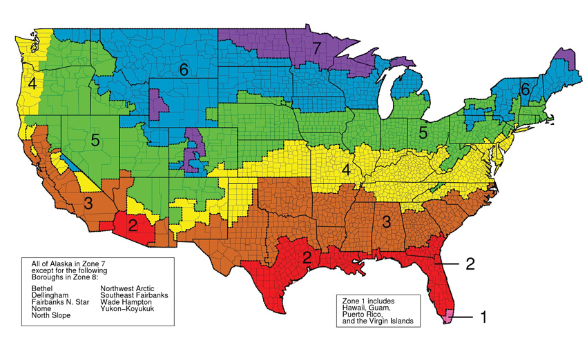
Image courtesy of ASHRAE
ASHRAE 90.1 defines climate-specific R-value minimums for the continuous insulation that must be incorporated into the building envelope.
The effectiveness of any insulation is denoted by its R-value, which measures its resistance to heat flow. The higher the R-value, the more effective a material is at resisting the flow of heat. The codes define prescriptive, climate-specific R-value minimums for the continuous insulation used in the building envelope. For example, in climate zone 3, which includes a wide swath of the Southeast from North Carolina through a significant share of Texas and parts of New Mexico, Arizona, and Southern California, ASHRAE 90.1-2007 requires that steel-framed, nonresidential, above-grade walls incorporate continuous insulation with a minimum R-value of 3.8 into the exterior wall assembly, outside of the primary wall structure.
NFPA 285 Compliance
One of the products commonly used to provide the now requisite layer of continuous insulation in exterior wall assemblies is foam plastic insulation, such as expanded polystyrene (EPS), extruded polystyrene (XPS), and polyisocyanurate (ISO). Unfortunately, foam plastic insulation is most often a petroleum-based product, and when it comes into contact with sufficient heat, it will combust. There are other combustible components that are often included in noncombustible exterior wall assemblies, including: combustible exterior claddings, water-resistive barriers, exterior insulation finishing systems (EIFS), metal composite materials (MCM), fiber-reinforced plastics, and high-pressure laminates. Certain types of combustible wall claddings, MCM for example, require NFPA 285 compliance when the installation is in excess of 40, 50, or 75 feet with multiple, specific requirements documented in the code.

Photo courtesy of Laminators Incorporated
An exterior wall assembly with ACM panels is being tested in accordance with the NFPA 285 test standard.
Although there are exceptions, the IBC requires that most exterior wall assemblies incorporating combustible elements be tested in accordance with, and comply with, the acceptance criteria of the NFPA 285 test standard. The test evaluates the distance that flames travel, vertically and laterally, when the exterior assembly is fully burning and is ultimately designed to determine whether or not an exterior wall assembly burns in a controlled enough manner to give building occupants time to get out of the building safely. Exceptions within the code recognize design scenarios where exterior wall systems are not required to meet the NFPA 285 standard, but they are very specific and should be reviewed thoroughly by the design team if the avoidance of the test standard is an ultimate design objective.
Notice


