Mitigating Water Leaks around Windows in Wood Framed Walls


Addressing Water Penetration Around Windows
The National Institute of Building Sciences (NIBS) is a nonprofit, nongovernmental organization that brings together government, the professions, industry, labor, consumer interests, and regulatory agencies to focus on safe, affordable structures for housing, commerce, and industry throughout the United States. One of its well-known programs is the Whole Building Design Guide (WBDG), which is a free Web-based portal providing one-stop access to up-to-date information on a wide range of building topics from a ‘whole buildings’ perspective. Development of the WBDG is a collaborative effort among federal agencies, private sector companies, nonprofit organizations, and educational institutions. As such, it has become a recognized standard for best practices in many aspects of building design and construction and is a resource that all architects should take advantage of (www.wbdg.org).
When it comes to windows and their penetrations in walls, the WBDG first encourages everyone to look at window systems realistically, stating, “When designing interfaces for an off-the-shelf window, you should start with the assumption that window frame corners, glazing seals, and perimeter sealant joints will leak at some point during normal service life.”1 While this might sound a little pessimistic at first, the fact is that windows are subject to a lot of different forms of stress that can, over time, cause them to degrade a little, malfunction, or fail completely. The best defense then is to have a backup system built into the wall assembly that will be there when needed to address the unwanted, but quite possible, penetration of water in or around the window. Flashing is an example of such a backup system.
Moving beyond individual products and materials, the WBDG is ultimately focused on how an assembly works together to maintain a quality installation and avoid construction defects of any type. It points out that in a typical wood-framed wall assembly, conventional siding or cladding is not usually meant to be impervious to water or vapor but instead is intended to shed it away or allow it to escape through weep holes or other means. The exterior sheathing behind the cladding is generally designed to be the resistive barrier that drains water down and out of the wall system to the ground or elsewhere. The plane of the sheathing also needs to provide resistance to air infiltration not only to prevent drafts but to prevent air borne moisture from penetrating into wall assemblies. When the multiple tasks of the sheathing are interrupted by a window opening, the WBDG states, “Careful detailing is required to integrate water/air/vapor barriers with the window frames and maintain their continuity at the window perimeters.”1 The key word here is continuity since the windows are creating the interruption or breach in an otherwise continuous sheathing plane designed to resist water and air. The means to achieving that continuity and avoiding common defects comes down to attention to detail in all typical window conditions.
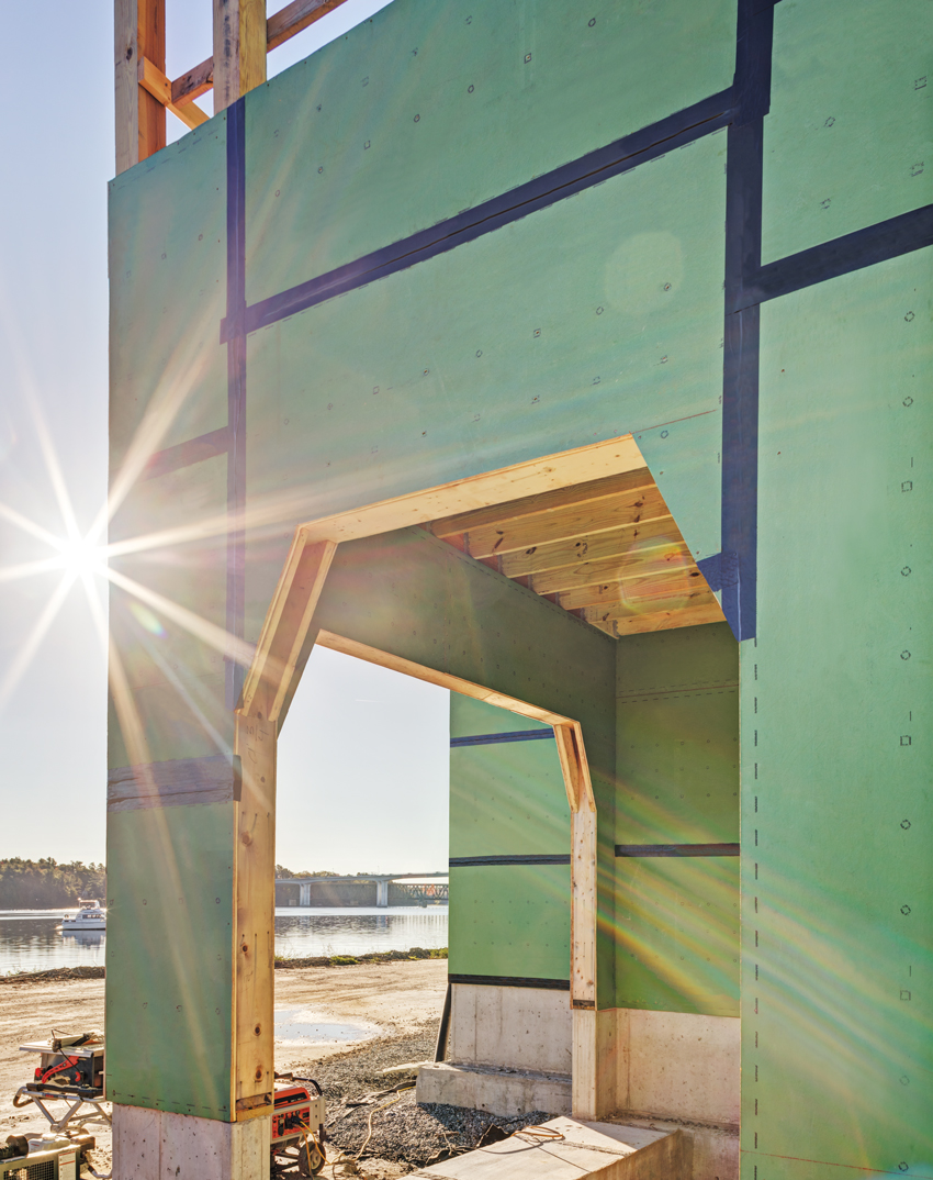
The Whole Building Design Guide and the IBC point out the need to address window openings as an interruption of the air- and water-barrier properties of the exterior sheathing.
Flashing in Codes and Standards
Building codes also recognize the importance of water/air/vapor barriers and their continuity around interruptions. For example, the 2015 International Building Code (IBC) is very clear about this point in Chapter 14: Exterior Walls, Section 1403.2, which reads, “Weather Protection: Exterior walls shall provide the building with a weather-resistant exterior wall envelope.” The code doesn’t dictate how that weather resistance is designed (that is the role of the architect), but it does require the weather-resistant performance of that wall, specifically with the ability to be water resistant. Further, it goes on to state, “The exterior wall envelope shall include flashing, as described in Section 1405.4.” Turning ahead to that section, we can read, “Flashing shall be installed in such a manner so as to prevent moisture from entering the wall or to redirect that moisture to the exterior. Flashing shall be installed at the perimeters of exterior door and window assemblies, penetrations and terminations of exterior wall assemblies, exterior wall intersections with roofs, chimneys, porches, decks, balconies, and similar projections, and at built-in gutters and similar locations where moisture could enter the wall.” In this instance, there seems to be a direct correlation between the code language and with the findings of the insurance industry on the common problem areas. The code is mandating what the rest of the design and construction community may already have learned: Flashing is required to cover over and around interruptions in the weather-resistant barriers and to redirect water or moisture away from the opening or interruption.
With all of the above in mind, let’s look closer at the typical different conditions around window openings.
Window Head Conditions
The head, or top of the window, is the first place that will receive any water draining from above it. In this case, it is clearly important that this water needs to be diverted around the window rather than be allowed to run down into the window. Equally important, the window head needs to be sealed along the junction or seam between the window and the sheathing to prevent intrusion there. Many windows come with nailing flanges that purport to be “self-flashing;” however, if water drains down behind those flanges for any reason, that claim is neutralized. Investigate thoroughly any such products and see what is really needed to allow for the window head to be properly flashed and protected.
The WBDG looks specifically at conventional window head flashing techniques and suggests using durable metal flashings such as zinc-tin coated-copper or stainless steel. However, other flexible products are also available and should be considered based on product capabilities and particular window installations. Either way, window head flashings need to be sloped to the exterior for drainage and provide an outturned drip edge over the top of the window frame. This type of head flashing should extend several inches beyond the window frame to be sure that water drops to the ground and does not seep back into the window unit. It is also common to provide a 4-inch minimum upturned leg above the window that is counter flashed with a wall waterproofing membrane adhered to the vertical leg of the metal flashing. If head flashing is already built in to the window unit, it needs to meet all of these criteria. It may also need to be counter flashed as well since the sheathing, and not the siding/cladding, is the protective drainage surface. Head flashings will end on the sides at the top of the window jambs and need to be sealed both to the window frame and to the jamb flashings to assure a continuous barrier all around the window. For window openings that do not allow extension of the head flashing beyond the opening (e.g. recessed windows), the suggestion is to use dual sealant joints in lieu of head flashing to capture water and direct it to the jamb flashings.
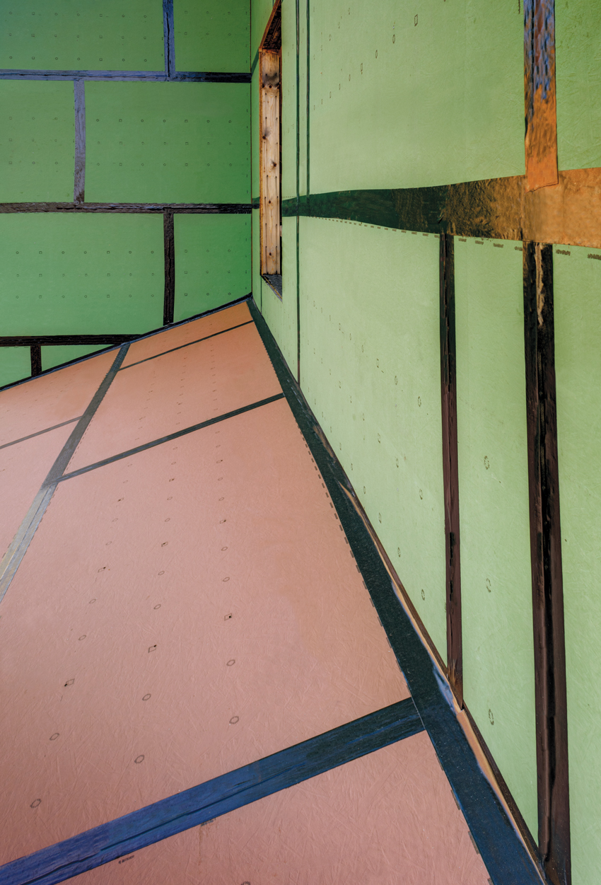
Pictured are the joints of a continuous air and water barrier on the exterior sheathing being sealed.
Window Jamb Conditions
The window jamb, or sides of the window opening, require some specific attention. As suggested in the window head discussion, the junction of the head and jamb is a critical condition since water can seep behind a water-resistive barrier if the window is not sealed properly around its jambs. The WBDG points out that jamb flashings may be metal but more typically are a flexible membrane of a variety of types. The intent is that this jamb flashing extends along not only the face of the sheathing around the window but also the full depth of the framing to catch and redirect any water away from the framing members. Where jamb flashings are part of an air-barrier system, they must be either metal or a membrane that is continuously supported by or adhered to a substrate capable of withstanding changes in air pressures. Otherwise, they will be prone to move and separate from the adjacent surfaces. The WBDG goes on to indicate that membrane flashings that bridge any gaps must be continuous for the full height of the window (i.e., no lap seams) because such gaps don’t allow the support needed to keep seams watertight. When it comes to integrating jamb flashings with wall waterproofing systems, the flashing must overlap the wall barrier and be fully adhered at their intersection to create a continuous connection between the two. Mechanical attachment (i.e., fasteners) of the jamb flashing to the window can be required if there is insufficient surface area on which to adhere the flashing and rely on adhesion alone. Any gaps between the flashing and the window frame must be fully and continuously sealed. Finally, at the base of the jambs, the jamb flashings must be shingled over the sill flashing to properly direct water to run down the jambs and into the sill pan.
Window Sill Conditions
The sill is the base condition of the window that may include a horizontal or sloped surface that is exposed to the weather. If the sill is not designed properly, then rain, snow, ice, or other weather-based water can sit on a sill, seep in behind the window, and find its way into the wall. Since that water will naturally move downward, flashing is needed under the sill to provide an additional layer of protection for the wall below it. Here again, the WBDG makes some recommendations. In cases where the sill flashing is exposed (i.e., not covered by siding or cladding), it suggests using durable metal flashings (e.g., zinc-tin coated-copper or stainless steel) that are sloped to the exterior and provide an outturned drip edge over the face of wall cladding. For the interior condition of such metal flashing, it suggests an upturned leg (1 inch minimum, greater for high-wind exposures) with end dams soldered water tight. Membrane flashings are also appropriate here, where the sill flashings are concealed and drain down into the wall cavity behind the cladding or onto sloped precast concrete or stone sills.
Clearly, each of these window opening conditions (head, jamb, and sill) is important to address and flash properly. There is one additional critical detail to take into account though, namely, the attachment of flashings. If nails or other metal fasteners are used, then those are necessarily penetrating the membranes that are intended to do the protective work of the flashing. Therefore, attachment details need to be coordinated with each other so that attaching one type of flashing does not penetrate another type of flashing, such as a sill detail penetrating the jamb flashing. Further, it is important that fasteners do not penetrate the horizontal portion of sill and head flashings and cause an interruption in the integrity of the flashing. If that is not possible, then those penetrations need to be covered over or counter flashed to assure the integrity of the system.
Notice