Detailing Continuity in Building Enclosure Systems


The Four Barriers of a Building Enclosure
The barriers of a building enclosure are based on good building science and the collective body of knowledge regarding current common construction techniques. This is particularly true in wood-framed construction, which continues to dominate most residential construction and a lot of commercial construction as well. In either case, the requirements for all of them are codified in the family of International Construction Codes adopted in most of the jurisdictions throughout the United States. The science behind the barriers are also each sophisticated enough to warrant specialty organizations that address them in multiple ways. We will look at each one briefly below, but keep in mind that there are many different products and solutions to achieve the performance and requirements cited. Further, as we will discuss, it is entirely possible to select a single product that provides more than one of the barriers, thus streamlining the specification and construction process with the possibility of achieving higher performance overall.
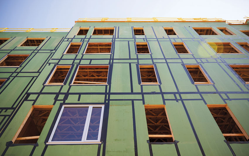
Photo courtesy of Huber Engineered Woods LLC ©2017
The IBC and IRC codes require a water-resistive barrier behind the exterior cladding plus a means for draining water along that barrier back out to the exterior.
Water-Resistant Barriers (WRBs)
The 2015 International Building Code (IBC) is very clear about the need for a WRB to protect the integrity of construction from bulk water (i.e., rain or other precipitation). Chapter 14: Exterior Walls, Section 1403.2 reads: “Weather Protection: Exterior walls shall provide the building with a weather-resistant exterior wall envelope.” Further, it goes on to state here and in Section 1405.4, “The exterior wall envelope shall include flashing…[which] shall be installed in such a manner so as to prevent moisture from entering the wall or to redirect that moisture to the exterior. Flashing shall be installed at the perimeters of exterior door and window assemblies, penetrations and terminations of exterior wall assemblies, exterior wall intersections with roofs, chimneys, porches, decks, balconies, and similar projections, and at built-in gutters and similar locations where moisture could enter the wall.” Clearly, the codes look at all of the same places that envelope commissioning agents do and that architects need to address.
The code doesn’t dictate how the required weather resistance and flashing is designed (that is the role of the architect), but it does require the weather-resistant performance of that wall, specifically with the ability to be water resistant. Given that there are a multitude of choices on the market, it behooves an architect to have a source of information on the performance of the products and the relevant data on how to use them. One such source is the Sealant, Waterproofing and Restoration Institute (SWRI) which is a nonprofit corporation that defines it membership as “the leading commercial contractors, manufacturers, and design professionals of our industry. [The] Institute provides a forum for those engaged in the application, design, and manufacture of sealant, waterproofing, and restoration products that is beneficial to the membership and the industry,” (www.swrionline.org).
One of the programs of SWRI is a product validation program that is designed to give an independent review and validation of the published test results of the various sealant, repellant, and coating products on the market. The stated intent of the program is “to provide specifiers and end users of [these] products an unbiased method to judge whether [these] products will perform at the levels of the manufacturer’s published data sheet for that particular product.” This can be very useful information when choosing a WRB and seeking to know if a particular product will perform as intended when applied to particular substrate surfaces as part of a specific construction condition.
Recognizing that there is more to continuity than just products (i.e., how they are used counts too), there are specialty consultants who focus on building enclosures. A nonprofit association known as RCI describe themselves as “an international association of building envelope consultants. Members specialize in design, investigation, repair, and management of roofing, exterior wall, and waterproofing systems.” These are the professionals who would likely be looking at the building sections and doing envelope commissioning in many cases. Their focus is on the best means to provide WRBs, roofing, and other protective surfaces for the building enclosure.
Working collaboratively to understand products and the way they are used by engaging organizations like those described above will help architects achieve the best set of WRB options for a particular building design. The goal should be to assure that the water resistance of a construction assembly performs as intended (i.e., shedding water or being fully water proof depending on the situation) without compromising or inhibiting the performance of other barriers in the assembly.
Air Barriers
An air infiltration barrier is required, not as part of the International Building or Residential Codes (IBC or IRC), but as part of the International Energy Conservation Code (IECC). It is typically placed along the plane of the exterior sheathing; however, it is worth noting that in a wood-framed wall with a multitude of individual materials and components, air infiltration can be difficult to control. The key to success lies first in the ability of a particular material to be considered a true air barrier. The codes rely on ASTM E2178: Standard Test Method for Air Permeance of Building Materials as the basis for determination. Hence, any individual material (or combination of materials) that can demonstrate compliance with this test showing a very limited air permeance can qualify as an air barrier material (maximum air penetration through a material at four-thousandths of a cubic foot per minute). The second key to the effectiveness of an air barrier is to look beyond the specific material and to its ability to be truly continuous as an entire system. That means any joints, seams, penetrations, or other breaches of the barrier need to be addressed in some manner as part of a total system. The codes then look to other specific tests; in this case, namely ASTM E2357: Standard Test Method for Determining Air Leakage of Air Barrier Assemblies and ASTM E1677: Standard Specification for Air Barrier (AB) Material or System for Low-Rise Framed Building Walls. Compliance is based on testing the entire assembled system, not just the individual materials in this case (maximum air penetration through an assembly at four-hundredths of a cubic foot per minute).
One of the leading sources for researching and testing materials and assemblies for air permeance is the Air Barrier Association of America (ABAA). It is a “national, not-for-profit trade association that consists of a wide cross section of stakeholders in the building enclosure industry. Its membership includes manufacturers, architects, engineers, trade contractors, researchers, testing and audit agencies, consultants, and building owners,” (www.airbarrier.org). Using data and information from this organization can help identify both individual materials and assembled systems that will qualify to properly restrict air flow through a roof or wall. It can also provide information on critical areas to address in those assemblies through its education and certification programs for professionals.
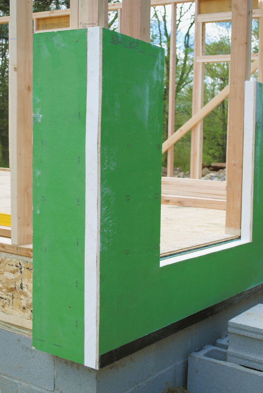
Photo courtesy of Huber Engineered Woods LLC ©2017
One way to add R-value to wall assemblies is to use single-panel sheathing systems with a built-in layer of continuous foam insulation integral to the back of the panel.
Thermal Barriers
Code compliance for thermal performance is predictably based on the IECC and begins with identifying the climate zone for a particular building project. The building type (commercial or residential) then comes into play, and the IECC uses charts and tables to identify the minimum performance requirements for the entire building thermal envelope. Following this process, the prescriptive requirements of the IECC point out that, in many climate zones, it is no longer enough to simply provide insulation materials between wood-framing members. This is because the wood framing itself is known to compromise the effectiveness of the insulation. Rather, the code requires many wall and roof assemblies to use continuous insulation (ci) to reduce the effects of “thermal bridges” and help mitigate heat conduction through the wood framing (IECC C402 and R402).
Traditionally, the continuous insulation has been applied to the exterior side of the wall on one side or the other of the sheathing. The intent is to cover all wall framing, floor framing, etc. with a layer of insulation that is continuous around the entire building envelope. In most climate zones where this applies, 1 or 2 inches of rigid insulation (R-5 or R-10) is typically used. It is important to note that making ci truly continuous around the full envelope requires some attention to detail such that the interface of the continuous insulation on the wall meets and seals with the continuous insulation in the roof, floor, or basement.
The amount of ci to use will be based on meeting overall building energy performance targets, either to meet code minimum levels or higher levels called for in voluntary standards, such as LEED or Passive House. Hence, computer-based energy models or similar methods will come into play to determine the predicted performance values needed (R-values or U-factors). How to achieve those levels is based on the type of insulation used and the way it is detailed into a construction assembly. Most commonly, rigid foam insulation of different types is used and needs to be adhered or attached to the sheathing. Combination products that include engineered wood sheathing and rigid sheathing in one product are also available, again simplifying the design, specification, and installation.
Vapor Retarder
The IBC and IRC recognize that water vapor or air-borne moisture is different from bulk water. They also recognize the potential for damage to a wood structure from vapor condensing in an exterior wall and deteriorating construction materials through rot, rust, or mold. Therefore, the IBC and IRC require protection against condensation in the exterior wall assembly and go on to clearly require specific solutions to provide that protection. Although the determination for applicability and type (identified as Class I, II, or III) of the vapor retarder is determined by the IECC climate zones, the requirement for its inclusion remains in the IBC/IRC. In the climate zones where the vapor retarder is required, it is called for on the “interior side of frame walls,” typically meaning on or behind the finished interior surface of the wall.
There is one caveat regarding vapor retarders in that a significant code exception exists in regard to the use of lower permeance Class I and II vapor retarders in the colder climate zones 5, 6, 7, 8, and Marine 4. Specifically, the exception applies if plastic foam continuous insulation is used outside of the studs in these zones since the ci will warm the stud cavity above the typical dew point. That means there is less chance of condensation in the wall cavity so less interior vapor control is required. The amount of ci used that triggers this exception varies based on the climate zone and whether 2-by-4 or 2-by-6 insulated framing is used. If the wall design meets the stated criteria, then a Class III or more permeable vapor retarder is all that is called for.
Notice


