Continuous Insulation in Framed Exterior Walls_OLD


Continuous Insulation
What is the solution to all of these thermal bridges and lack of performance in the wall system? For those who want to stay with the tried and proven method of framed construction, the answer is in providing continuous insulation (CI) that is not interrupted by the framing. Such insulation is commonly thought of as a rigid foam insulation made into board products, foamed in place on site, or in the newest instances, included as an integrated part of the exterior wall sheathing. In any of these cases, in order to make the insulation truly continuous, it needs to be placed either on the inside or outside face of the studs, with the outer surface usually being preferable. An outer face installation allows for complete coverage of all framing, including headers, corners, floors, and other structural elements. It also doesn’t interfere with interior dimensions or finishing and, as we will see, can be managed well for moisture and water vapor in a wall assembly.
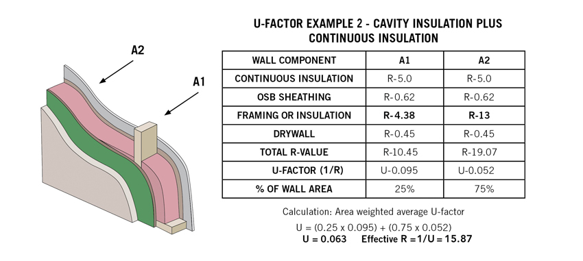
When continuous insulation is added to a framed wall assembly, its R-value is added to both the R-value of the framing and the stud cavity insulation.
So how much of an impact can this continuous insulation have on the wall? Let’s look at another U-factor calculation example but this time, let’s see the effects of continuous insulation over the outside of the wall assembly. In U-Factor Example 2, we will use 2-by-4 framing at 16 inches on center with R-13 insulation in the cavities (instead of the previous 2-by-6 framing with R-20). Again, we need to calculate the A1 and A2 performance through the studs and the cavity insulation respectively. However, this time we are able to add in R-5 to both cases in order to account for the layer of continuous insulation that covers the entire wall. The results in this scenario show that the total R-value through the studs plus the continuous insulation and sheathing has increased to R-10.45 (U-0.95) compared to an R-19.07 (U-0.052) through the insulated portions. Assuming here 25 percent framing and 75 percent insulating areas, the weighted average for this total wall is an overall effective R-value of R-15.93 (U-0.063). Comparing this example to the first one, we find virtually the same overall results using 2-by-4 framing with R-13 cavity insulation and R-5 continuous insulation as using 2-by-6 framing with R-20 cavity insulation. The 2-by-6 cavity insulation alone has to have a higher R-value (R-20) than the sum of the 2-by-4 cavity insulation plus the continuous insulation (R-13 + R-5 = R-18) in order to make up for the thermal bridging of the studs and still perform as well overall.
Continuous Insulation Choices
As noted, there are choices in the type of materials that can be selected and specified as continuous insulation. Over the past few decades, nonstructural insulating sheathing products of different types have come on the market and are now available in common construction sizes and in varying thicknesses. These products are essentially rigid foam insulation that may or may not have a facing depending on the material. They are foamed from plastics such as polystyrene, polyurethane, and polyisocyanurate, with each carrying different thermal and physical characteristics. Of these, polyisocyanurate (or simply “polyiso”) has become popular because of its performance. According to the Polyisocyanurate Manufacturers Association (PIMA), polyiso has the highest R-value per inch of any rigid foam board insulation. It also points out that polyiso is unique in that the R-value per inch increases with the thickness of the foam, so 3 inches of polyiso has a higher R-value per inch than 2 inches. This superior performance compared to other foam insulation products can mean less material is needed overall, making it very cost effective.
Of course, in framed walls, there is also the need for solid sheathing over the studs that can provide structural bracing for the wall and a nailbase for the attachment of siding, cladding, brick ties, etc. Most foam sheathing products aren’t rated to be structural and don’t necessarily provide a good nail base. That usually means that the foam insulation is put up after structural sheathing goes over the studs. In some cases, the structural sheathing may only be required in strategic locations, such as corners, and thicker rigid insulation can be put up in between. However, in some cases, another layer is needed to provide a nail base or else the exterior cladding needs to be carefully attached to the studs. This multistep process obviously adds to the labor involved in constructing the wall, but it also requires attention to the fastening pattern.

Continuous insulation is available as part of an exterior sheathing system that can be used as a structural panel when properly fastened according to the manufacturer’s instructions.
One of the more simplified choices to address both the structural and thermal needs of exterior continuous insulation is a single product that contains both a structural sheathing panel and an integrated layer of continuous insulation. This type of nail-base insulation product has been commonly used on commercial roofing systems for years, but it has taken some engineering and development for it to be ready for use on walls. As a single, combined product, it eliminates a labor step by installing both continuous insulation and a structural, nailable sheathing all at once. Some are even preprinted with the manufacturer’s recommended nail patterns to take the guess work out of assuring appropriate structural strength. And to further assure structural integrity, the best option is to rely on a product that has been tested as a complete, combined panel under laboratory conditions. One engineered wood exterior sheathing manufacturer has obtained third-party documentation through the International Code Council’s Evaluation Services to be used as an acceptable structural panel.1 From a thermal performance standpoint, this multifunctional, single-panel exterior sheathing system product is commonly available with different thicknesses of continuous insulation ranging from R-3 to R-12.
Continuous Insulation in Codes and Standards
With the clear benefits demonstrated in using continuous insulation and its increasing availability as a practical material, it is not surprising that building and energy codes are not only recognizing it, but in some cases are now requiring it to be used. In fact, some designers might say they are surprised that it hasn’t happened sooner. For purposes of our discussion here, we will be referring to the 2015 codes published by the International Code Council, specifically the 2015 International Residential Code (IRC), the 2015 International Building Code (IBC), and the 2015 International Energy Conservation Code (IECC).
2015 IRC and IBC
As general construction codes, both the IRC and the IBC have always been similar in intent (i.e., general health, safety, and welfare of people in buildings) but different in their focus on different types or classes of structures. The IRC covers detached and attached one- and two-family residential units, including attached townhouses, up to three stories in height. The IBC covers everything else, including residential buildings, such as multifamily occupancies like apartments, dormitories, boarding houses, hotels, and motels.
Both the IRC and IBC allow for either metal- or wood-framed wall construction with particular limits based on fire and safety criteria. They also both address durability and protection of the construction assemblies by requiring a weather-resistant barrier (WRB) over exterior wall sheathing and in some climate zones, a warm-side vapor retarder. Both of these are intended to protect the wall assembly from being damaged by water or weather intrusion, which could lead to possible decay or mold that is not only a concern for building owners but also a possible health risk to occupants.
2015 IECC
This latest version of the Energy Conservation Code is essentially two documents in one—it contains six chapters for residential buildings and a separate but similar six chapters for commercial building energy conservation requirements. There are several critical points to understand with this code:
- Residential vs. Commercial: The applicability of the IECC residential portion is actually different from the distinction between the IBC and IRC. Under the IECC, the residential portion applies not only to detached one- and two-family dwellings and multiple single-family dwellings (townhouses) as in the IRC, but also to Occupancy Group R-2, R-3, and R-4 buildings that are permanent residences and are three stories or less in height above the grade plane. These occupancy group buildings are defined in the IBC to include things like apartment buildings, dormitories, halfway houses, and long-term care facilities. The rationale behind this distinction appears to be that these permanent, residential classifications up to three stories in height are more akin to residential construction and therefore should be subject to the more appropriate and stringent requirements of the residential portion of the IECC. R-2, R-3, and R-4 buildings that are more transient in nature or over three stories in height are to follow the commercial provisions of the IECC.
- Climate Zones: The IECC recognizes eight different climate zones (simply numbered 1 to 8) across all states and counties in the United States. These climate zones are calculated on the basis of the need for heating or cooling using common degree-day methodology. Climate zones 1 and 2 show up in the warmest areas in Florida and the Gulf Coast, plus an area around southern Arizona. Climate zone 3 covers a varying-sized swath from the southeastern United States across to much of California. Climate zones 4, 5, and 6 cover most of the country from coast to coast above the southern states. Climate zones 7 and 8 identify the coldest areas in places like northern Maine, Minnesota, some places in the Rocky Mountains, and in Alaska. Some portions of the country are further identified as marine, dry, moist, or warm-humid based on criteria identified in the code.
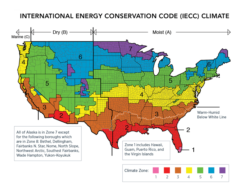
Source: U.S. Department of Energy
The International Energy Conservation Code has established eight climate zones across the country based on heating and cooling needs as well as humidity conditions.
- ASHRAE 90.1: The American Society of Heating Refrigeration and Air Conditioning Engineers (ASHRAE) has long been the authority on energy use in mechanical equipment in buildings and has also developed standards related to the building enclosure, including exterior walls. The standard known as ANSI/ASHRAE/IES 90.1: Energy Standard for Buildings Except Low-Rise Residential Buildings has served as a benchmark for energy use in commercial buildings in the United States and around the world. The IECC recognizes this standard as an “equivalent” rather than identical set of criteria to demonstrate energy code compliance in commercial buildings (not applicable to low-rise residential buildings). It is important to note that there are some differences between ASHRAE 90.1 and the IECC, such as mechanical and electrical requirements being somewhat more stringent, but building enclosure requirements are a little more lenient in some cases. However, design teams cannot mix which standard to follow on a single project—either all of the requirements of the IECC must be followed or all of the requirements of ASHRAE 90.1 must be followed.
- Prescriptive vs. Performance: Almost all codes contain both prescriptive and performance options to demonstrate compliance. Prescriptive requirements are based on a printed set of criteria that can be looked up on a table or otherwise be readily identified based on the specific conditions of a building. They tend to follow an “if/then” approach, as in if the building is located in “x” climate zone, then “y” level of wall insulation must be provided. By identifying the conditions specific to a particular building, the appropriate variables can be selected and a determination easily made as to whether it complies with code. By contrast, the performance path takes the approach of identifying the outcome and leaving it to the designer to prove that it has been met. In this case, the individual prescriptive requirements can waived if it can be shown that the overall objective has been met. Under this approach, the insulation levels of walls, floors, roofs, etc. may all vary provided the overall energy use of the building is within code performance limits. Proving this claim usually requires some type of computerized analysis following specific methodologies.
- Prescriptive R-Value Requirements: For building designs that are fairly straightforward, it is common to look at the prescriptive requirements of the energy code. IECC Residential Table R402.1.2 shows the minimum requirements for insulation R-values in all opaque components of the building envelope. The first thing to notice is that there are separate rows for each climate zone. Hence, to determine what the minimum R-value requirements are for insulation, the designer must pick the correct climate zone. The columns of the table then list requirements for roofs, walls, floors, and doors. For wood-framed walls, there are choices of higher levels of cavity insulation (suggesting 2-by-6 construction) or lower levels of cavity insulation, plus a minimum amount of continuous insulation (suggesting 2-by-4 construction). For commercial applications, Table C402.1.3 provides similar comparative information based on climate zones.
- Prescriptive U-Factor Option: Instead of showing compliance purely on the basis of the R-value of the insulation, the code allows calculations of the entire assembly to be performed to demonstrate that it is below the maximum U-factor. In this case, the designer would need to produce calculations similar to our prior examples, either showing all cavity insulation or with the addition of continuous insulation. Note, however, that under this method, there is a dramatic adjustment required when metal studs are used. Table C402.1.4.1 of the IECC identifies correction factors that must be used for the effective R-value of cavity insulation. The correction factors are calculated based on the nominal stud depth (i.e., 3½, 6, or 8 inches), the spacing of the framing (16 or 24 inches on center), and the cavity R-value of the insulation (R-13 to R-25). So, for example, a common exterior wall framed with 6-inch metal studs at 16 inches on center and filled with R-19 insulation between the studs has a correction factor of 0.37 and therefore must use an effective R-value of only R-7.03. This correction factor and dramatic 63-percent reduction in R-value of the insulation accounts for the thermal bridging of the very conductive metal framing members.
Based on all of the above, it should be clear that showing compliance with the IECC requires some attention to detail in terms of building types, climate zones, cavity insulation, continuous insulation, and thermal bridging.
Notice