Who’s the Culprit in WRB-AB Leakage?


Test Setup
The specific test that we are looking at was carried out by RDH Building Science in Waterloo, Ontario, in 2017. RDH is a consulting, research, and forensics firm that focuses on helping clients make informed decisions that lead to durable and effective buildings. RDH Building Science Laboratories contributes to that goal by providing high-quality research and development services. The testing that was performed was based on ASTM E331-00 (2016): Standard Test Method for Water Penetration of Exterior Windows, Skylights, Doors, and Curtain Walls by Uniform Static Air Pressure Difference. This standard describes the physical means and methods required to conduct the test and then provides the required air and water pressure levels and amount of time for which each tested wall sample must be subjected.
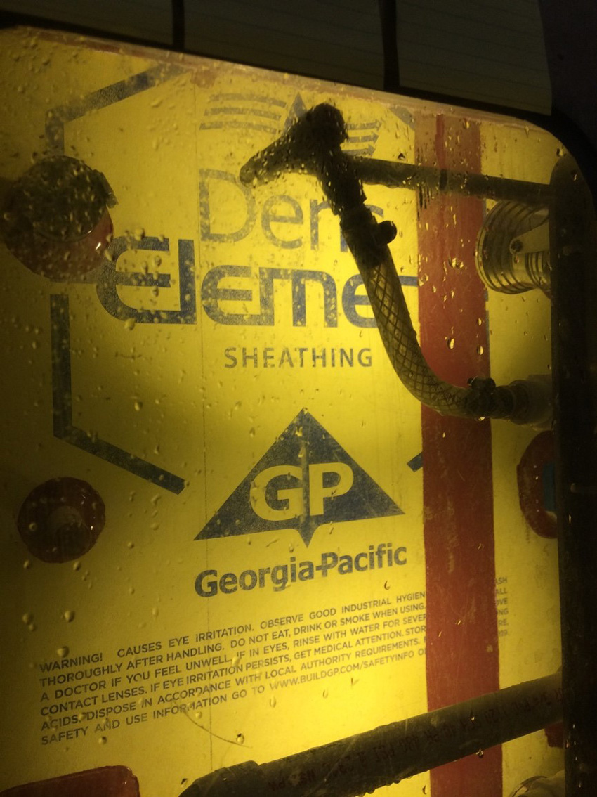
RDH constructed six test wall panels, 4 feet wide by 8 feet tall, as the basis for the testing. All six of the test panels were representative of commonly used systems that are code-compliant for typical commercial buildings using metal framing with exterior gypsum board sheathing. Five of the panels focused on different means of providing cladding support with different fastening approaches. Across the six panels, three different WRB systems were employed: athin-mil fluid-applied WRB, a thick-mil fluid-applied WRB, and integrated sheathing.
In order to address the different cladding attachment approaches, two different metal Z-girt arrangements were tested: flange down, which is the proper and recommended method, and flange up, which is commonly seen in the field. This arrangement was tested to see if it made any actual difference in the integrity of the WRB. This arrangement may also increase the risk of liquid water accumulating on the face of the exterior sheathing. In addition to Z-girts, two different cladding attachment clip types were included in the test setup: spacers made with a fiberglass material with lower thermal transmission rates than pure metal, and thermally broken metal spacers. These variations provided a full range of common construction techniques in the interest of providing the most relevant data.
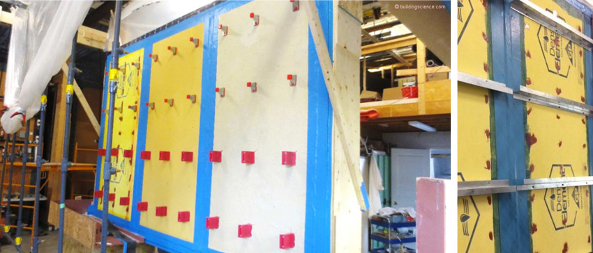
The testing methodology included different types of spacers and Z-girts in differing configurations constructed as part of the six different test panels, each of which were 4 by 8 feet in size.
In addition to the girts and clips, one of the 4-by-8-ft test panels was constructed using a layer of 2-inch-thick XPS insulation board applied directly over the exterior sheathing. The insulation was attached using 4-inch-long, self-drilling, self-tapping screws with large (1-inch-diameter) plastic cap washers. For testing purposes, the top edge of the insulation was cut to bevel backward toward the wall, forcing some water behind the insulation.
Note that none of the 4-by-8-ft test panels contained any other locations for water to penetrate other than cladding support connections. By design, there were intentionally no windows, pipe penetrations, joints, material transitions, or other potential water-entry locations. This kept the focus of the testing purely on the cladding attachment system over the WRB/sheathing without introducing the additional variables of wall openings or other penetrations.
In order to test differing installation techniques commonly seen in field construction, two cladding attachment methods were used to secure the clips and Z-girts. The first group was installed tightly against the sheathing or WRB surface, and the second group was spaced away from the sheathing or surface with different spacer thicknesses to allow water to flow behind the attachment device. The rigid insulation board was installed in a similar manner. One section was installed tight to the sheathing, and two other sections were spaced away from the sheathing at different spacing thicknesses to create a gap between the back of the insulation and exterior face of the sheathing.
Test Methods
With all of the panels constructed, set up, and in place, water-spray nozzles were then positioned on supports all facing the test wall sections and all in accordance with the protocols and specifications of ASTM E331. The intent of the spray nozzles is to simulate rain conditions at different intensities as controlled by the laboratory personnel and following the parameters of ASTM E331. In order to test for wind conditions, negative air pressure was created on one side of the wall and positive air pressure on the opposite side, again all in accordance with ASTM E331 protocols. Note that these water and wind protocols establish set conditions and amounts of time that the wall panels need to be subjected to those conditions. The building codes then determine the minimum level of performance that a wall needs to meet in order to be compliant. Since the intent of the testing was to take the wall assemblies to the point of failure (i.e., find out what it takes for them to leak), the levels of water and air pressure were incrementally increased up to and then beyond the code requirements. Nonetheless, all of these conditions were administered appropriately in accordance with ASTM E331 methodology.
For testing the water resistance of the wall panels, code-compliant water-resistance testing levels require a continuous spray of 5 gallons per hour per square foot for a period of 15 minutes. The actual water application rate during the testing was higher at 7.5 gallons per hour per square foot and longer at a full 60 minutes. The same water-spray application was repeated for an additional 60 minutes for each of the five different air-pressure conditions (i.e., 5 hours of total testing instead of 15 minutes).
The test panels were subjected to water-spray nozzles and air-pressure differences according to ASTM E331 protocols to simulate code minimum conditions and more extreme weather conditions to determine the points of failure.
Similarly, air pressure requirements for code compliance call for a single pressure difference of 140 pascals (Pa) between inside and outside (equivalent to a sustained wind of approximately 25 miles per hour). The testing actually included five other air pressure conditions:
- 0 Pa: equivalent to calm wind conditions;
- 300 Pa: equivalent to sustained winds of 55 miles per hour;
- 600 Pa: equivalent to sustained winds of 71 miles per hour;
- 900 Pa: equivalent to sustained winds of 85 miles per hour; and
- 1250 Pa: equivalent to sustained winds of 100 miles per hour.
With this all-encompassing test methodology, RDH hoped to learn where the weaknesses lie in different types of wall assembly systems and under what air and water conditions.
Notice


