Wind Design for Roof Systems and ASCE 7


Figure 3: External Pressure Coefficients, GCp, for ASCE 7-16.
Determining Velocity Pressure. All of the previously discussed assumptions and selections and characterizations of the building are used to determine the Velocity Pressure for a roof project. The Velocity Pressure is the ‘foundational’ load that is used to determine the design wind pressures for each zone of a rooftop. It’s important to recognize there are two basic steps used to determine design wind pressures acting on a roof. The first step is to determine velocity pressure; the second step is to use velocity pressure to determine design wind loads for roof zones (e.g., field, perimeters and corners).
The equation to determine velocity pressure varies slightly in ASCE 7-05, ASCE 7-10 and ASCE 7-16. ASCE 7 uses the following base equation to determine velocity pressure (qh):
-
qh = 0.00256 (Kz)(Kzt) (Kd) (V2)(I)
Where:
qh = velocity pressure at mean roof height
Kz = exposure coefficient based on exposure and height
Kzt = topography factor (likely 1.0)
Kd = wind directionality factor (Components and Cladding uses 0.85)
V = basic wind speed for the location
I = Importance Factor (based on Occupancy Category)
Each version of ASCE 7 uses a variation of the above equation. In ASCE 7-05 for example, I—the Importance Factor—is in ASCE 7-05 only. The Importance Factor was absorbed into the wind maps, which means for ASCE 7-10 and ASCE 7-16, the Velocity, V, is adjusted within the wind speed maps. Also new in ASCE 7-16, a ground elevation factor (Ke) can be used to reduce pressures at higher elevations, or it can more conservatively be set to 1.0.
Determining Design Uplift Pressures
This is the second step in determining design wind pressures. After determining the velocity pressures, the next step is to calculate the design uplift pressures specific to the interior (if applicable), field, perimeter, and corner zones of a roof. Design uplift pressures are adjusted by multiplying the velocity pressure (qh) by the appropriate external pressure coefficients (e.g., GCp), as shown in Figure 3. The external pressure coefficient values are based on roof zones and the appropriate “effective wind area” (which we won’t go into in this article). Effective wind area is the tributary area for the element being considered, and 10 square feet is typically used for roof systems.
The internal pressure coefficient values are based on the building design (i.e., the enclosure classification). See Figure 2.
Determining Wind Uplift Resistance
The primary method for determining a roof system’s wind uplift resistance (aka, capacity) is through physical testing. The test methods to determine wind resistance are listed in the IBC Section 1504, Performance Requirements.
In the 2003 and 2006 International Building Code (IBC), for wind resistance of non-ballasted roofs, the codes state that built-up, modified bitumen, adhered or mechanically attached single-ply, through fastened metal panel roof systems, and other types of membrane roof coverings shall be tested in accordance with FM 4450, FM 4470, UL 580 or UL 1897.
In the 2009, 2012, 2015 and 2018 versions of the IBC, for wind resistance of non-ballasted roofs, the codes state that built-up, modified bitumen, adhered or mechanically attached single-ply roof systems, metal panel roof systems applied to a solid or closely fitted deck and other types of membrane roof coverings shall be tested in accordance with FM 4474, UL 580 or UL 1897.
These tests are run by approved testing agencies. FM Approvals, Underwriters Laboratory, Intertek, NEMO, PRI, and others can perform testing—according to the code-approved test methods—that can be used to determine a roof system’s capacity.
It is important that the testing method used to determine the wind-uplift capacity of a roof system is listed in the applicable building code.
Approval Listings. The tested roof systems are found in approval listings. Approval listings are maintained by various entities, such as government agencies, testing laboratories, and even a trade association. Examples of government agencies with approval listings include: Florida Department of Business and Professional Regulation, Miami Dade County, and Texas Department of Insurance. Testing laboratories that have listings of rated roofing assemblies include Underwriters Laboratories and FM Approvals. And lastly, SPRI sponsors the Directory of Roofing Assemblies (DORA) which is an online database of tested assemblies.
Case Studies
The changes to ASCE 7-16 are generally increasing the design wind pressures for roof systems. Increased design wind pressures leads to the use of higher-capacity roof systems. To what extent is this affecting the roofing industry?
Two buildings of different sizes and heights in two cities in the U.S., one centrally located and one along the Gulf coast, were studied to compare design wind pressures based on ASCE 7-10 and ASCE 7-16. By assessing the required roof-system capacity for all roof zones in conjunction with the increases in the size of roof zones, real numbers can be assessed to help answer the question “by how much will ASCE 7-16 affect the low-slope roofing industry?”
Note: While analysis of two building types in two cities does not represent a significant study, this study offers an example of how the 2016 version of ASCE 7 is going to affect installed roofing systems over the next decade.
Case Study Parameters and Design Wind Pressures. Design wind pressures (DWP) were determined for two building types in two cities. DWPs were based on varying the Risk Category and Exposure. Figure 4 shows the building types, cities, variables and constants.
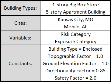
Figure 4: Case study parameters: building type, cities, variable, and constants.
Notice


