Roofs for Cold Storage Buildings


Design Values
If a roof system designer chooses to perform a dew-point or hygrothermal analysis to confirm the placement of the vapor retarder/air barrier, the following is needed:
- Interior dry bulb temperature
- Interior relative humidity
- Exterior dry bulb temperature
These values are theoretical constant values based upon design assumptions for a single point in time, yet in reality, these change from day to day and season to season.
Roof Insulation
Insulation plays a critical role in the building enclosure performance of a cold storage building. To minimize the potential for interior condensation, appropriate amounts of insulation should be used so the interior surfaces of the building enclosure are kept above the dew point. Insulation type and R-value selection are affected by numerous factors, such as cost, desired energy efficiency, suitable material properties, interior design temperatures and climatic conditions. Figure 5 offers suggestions for minimum R-values for roof insulation in cold storage buildings.5
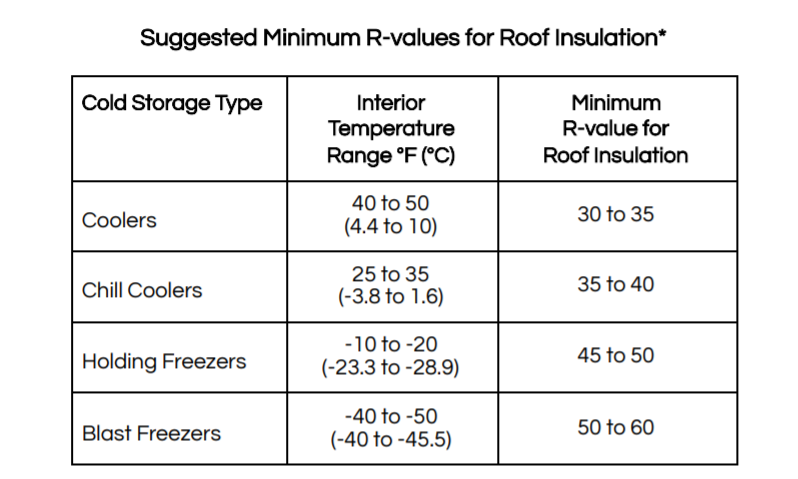
FIGURE 5: Shown are the suggested minimum R-values for roof insulation used in cold storage buildings, adapted from 2018 ASHRAE Handbook, Refrigeration.
The type of insulation used should be suitable and compatible for use in a cold storage building. A commonly used insulation type is polyisocyanurate insulation (polyiso), which has the highest R-value per inch compared to other insulation types used in the roofing industry.
Thermal Shorts/Thermal Bridging
Designers should pay close attention to thermal shorts (e.g., gaps between boards) and thermal bridging (e.g., metal fasteners and plates) when designing roofing systems over cold storage buildings. To reduce the effects of thermal shorts, roof insulation should be installed in at least two layers with offset joints—vertically and horizontally—to minimize air leakage and movement. Insulation boards should be installed so that there are no gaps present.
To reduce the effects of thermal bridging (e.g., loss of R-value, condensation potential), the roof membrane and upper layer(s) of rigid board insulation should be adhered. Mechanical fasteners should be avoided as the securement method for the roof membrane and upper layer(s) of rigid board insulation. When the substrate is a nailable deck, such as steel or wood, the first layer of insulation (i.e., the layer in direct contact with the roof deck) may be mechanically attached. Subsequent layers should be installed with adhesives to reduce or eliminate thermal bridges. When the substrate is concrete, adhesives or fasteners can be used to install the first layer of insulation, with subsequent layers adhesively attached.6
Expansion and Contraction
Accommodation should be made for thermal movement in cold storage buildings. Building movement may lead to tearing of or damage to a vapor retarder/air barrier or the roofing system. Pipes in roofs and walls may move due to thermal expansion and contraction as well as vibration, so it’s important to select pipe penetration flashings that can accommodate movement, such as pre-manufactured flashing accessories. Additionally, terminations at roof perimeters are subject to expansion and contraction, and the edge termination should be selected to accommodate movement if it is expected to occur. Typically, the largest amount of movement occurs during the drawdown period, which is the period in which the cooling systems are initially turned on after construction is complete. As a best practice, after the drawdown period is complete, the roof should be inspected for locations where expansion and contraction has occurred. Indications such as loose termination bars and cracked sealant joints, should be repaired.
Air Leakage and Water Vapor Management
Cold storage buildings are maintained at temperatures that are most often much lower than the exterior temperature. In this case, the warm, moist outside air wants to move to the interior of the cold storage building. This is especially the case in southern climates and is generally true for most geographic locations in the United States for most months of the year. Therefore, the direction of the vapor drive is predominantly from the exterior to the interior. This means the roofing membrane will act as the vapor retarder and air barrier, which keeps vapor and air from moving into the roof system and creating condensation problems.
There may be times during the year in colder climates where the warmest cold storage buildings—a cooler with a temperature range from 32–55F (0–13C)—may experience a vapor drive from the interior to the exterior because it’s colder outside than the interior. However, this is not likely problematic for two reasons. First, the amount of absolute humidity inside a cold storage unit is low because of its low temperature and relative humidity.7 There just isn’t a lot of moisture relative to the interior of, say, an office building. Second, because vapor drive also relates to pressure differences, a cold, dry space (the interior of a cold storage unit) does not exert a pressure significantly greater than the cold, dry air of the exterior in a winter climate. Ultimately, a cold storage unit in a northerly climate should not experience a moisture gain within the roof system. And any moisture gained during the winter will be driven back into the cold storage portion during the warmer summer months.
Problems occur when there are paths for air and water-vapor movement within the building enclosure. It’s imperative that the vapor retarder and roof system be continuous, tied to the wall air barrier and completely sealed at:
- Laps and seams.
- Roof penetrations (i.e., pipes, structural members, mechanical curbs, roof hatches, etc.).
- Roof-to-wall interface/intersections.
Special attention should be paid to steel roof decks which are used in many cold storage buildings because of their ability to allow significant lateral movement of air within the deck flutes. Limiting the number of penetrations through the roof assembly is also prudent. If a separate vapor retarder/air barrier is used at or just above the roof deck, avoid attaching the roof system through the vapor retarder with mechanical fasteners for cold storage buildings. This helps maintain the vapor retarder’s integrity.
Vapor-Retarder Perm Ratings
Vapor retarders are typically membranes with relatively low permeance values, but not all vapor retarders are equal. There are three classes of vapor-retarder materials, as shown in Figure 6.
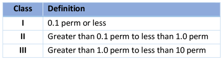
FIGURE 6: Shown are three classes of vapor retarders; each class has different perm ratings.
Most roof membranes are Class I vapor retarders. Perm ratings for single-ply membranes range from 0.03–0.06 perms. An example of a Class II vapor retarder is asphalt felts, which have perm ratings ranging from 0.3–0.8 perms. Examples of Class III vapor retarders are latex or acrylic paint. Class I vapor retarders should be used on the outer surfaces of cold storage buildings that are designed and built using the EES method.8 If a second vapor retarder is used at the deck level (to prevent construction moisture from infiltrating the roof system), a Class III vapor retarder should be used to allow some downward drying. It’s important to note that these are material ratings; the entire vapor and air management system needs to be designed and installed correctly for proper functionality.
Details
All of these concepts—moisture and vapor drive, thermal control—come together at the intersections of systems (e.g., roofs and walls) and penetrations, and these are the locations that should have construction details developed for use during the bid phase and certainly during the construction phase.
Thermal efficiency considerations include multilayer insulation, where fasteners and adhesives are located within the system. Designs with the first layer mechanically attached and the upper layers adhered is shown to be most effective.9 Because air leakage is an important part of energy efficiency, consider the direction of the vapor and air drive; when placing the air barrier on the exterior, it’s important to locate the air seals toward the exterior so they are positioned to be the first line of protection against air infiltration.
Consider expansion and contraction as well as differential movement. Cold storage buildings can experience a larger temperature differential from interior to exterior given the low interior temperatures, relative to typical office buildings that have interior temperatures of approximately 70F.
Using insulation with high R-value per inch reduces the total insulation thickness. This may also reduce the length of fasteners, depending on attachment design. One way to eliminate the need for tapered insulation is to slope the structural deck.
Considering the location and constructability of the connections and tie-ins for the air-barrier details is long-term risk management. The roof membrane is the vapor-control layer and the air-control layer for the primary vapor and air drive for cold storage buildings. Of the two, the air-control layer is more critical for long-term success.
Special attention should be paid to steel roof decks, which are used in a large number of cold storage buildings, because they pose a detailing issue regarding air control. It’s challenging to air-seal steel roof decks at walls and penetrations. Deck flutes can serve as “conduits” or pathways through which air and air-transported moisture can flow. To minimize airflow, flutes can be filled with closed-cell spray polyurethane foam (SPF) at walls and penetration locations. Figure 7 is an example of a roof-to-wall construction detail showing SPF used to create a continuous air barrier from the wall to the roof.
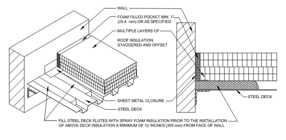
FIGURE 7: Detail 350, Air Seal Detail at Steel Deck to Wall Interface, courtesy of GAF
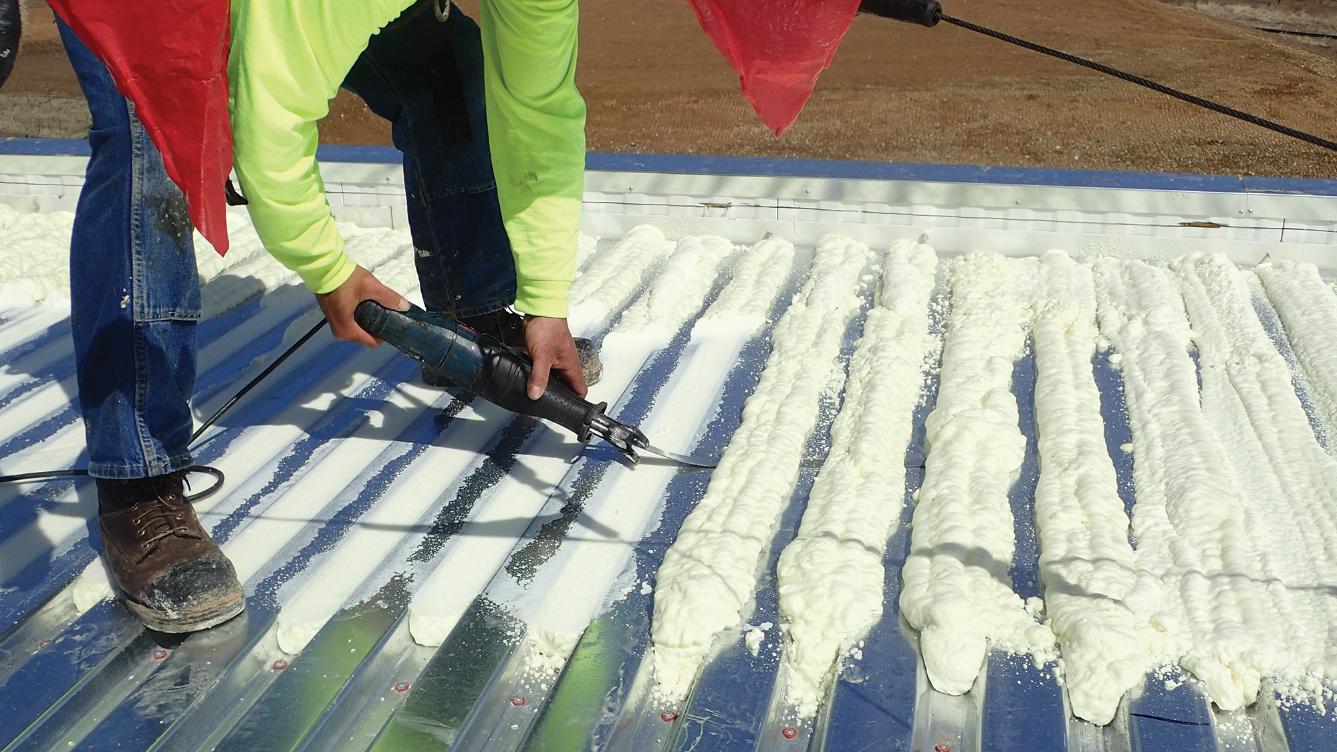
Photo courtesy of Matt Dupuis, SRI
PHOTO 3: Shown is the installation of spray polyurethane foam in the flutes of a steel deck.
It’s important to recognize that a steel deck meets a wall with two different profiles because its profile is not the same in each direction. The foam may need to extend a minimum of 12 inches along the flutes when the flutes are perpendicular to the wall to prevent the communication of air from the roof to the wall, which can result in interior icicles. When flutes are parallel to the wall, flutes that fall within 12 inches of the wall should be sealed. Two construction details are needed to ensure that air is properly controlled at the roof-to-wall intersection.
Notice


