Roofs for Cold Storage Buildings


Air Leakage and Vapor Diffusion Principles
Air-transported moisture is a more significant issue than vapor drive because of the relative amount of moisture transported by each process.
Research data illustrates how even small openings can affect overall air leakage performance. For example, only about one-third of a quart of water will diffuse through a continuous 4-foot x 8-foot sheet of gypsum during a one-month period, even though gypsum board has a very high perm rating. However, if there is a 1-square-inch hole in this same sheet of gypsum, about 30 quarts of water can pass through the opening as a result of air leakage.3 This is essentially 100 times more moisture gain due to air movement through a small hole versus the moisture gain from diffusion. This relationship is illustrated in Figure 3. This example illustrates that air leakage can cause more moisture-related problems than vapor diffusion. This is why the International Energy Conservation Code has mandated air barriers for new construction since 2012.
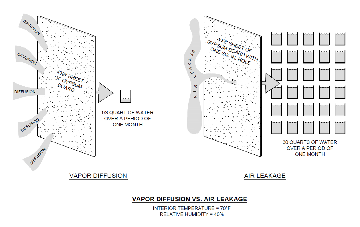
FIGURE 3: Shown is the difference in the amount of moisture that moves via diffusion and via airflow.
Accordingly, it’s critical that a vapor-retarder system be continuous when used in cold storage buildings so it also serves as an air barrier.4 Most commonly, the roof membrane serves as the vapor retarder/air barrier. Penetrations and the roof-to-wall interfaces should be sealed to prevent air leakage (see Photo 2) because discontinuity will allow air to flow through the discontinuity, which can then lead to condensation problems.
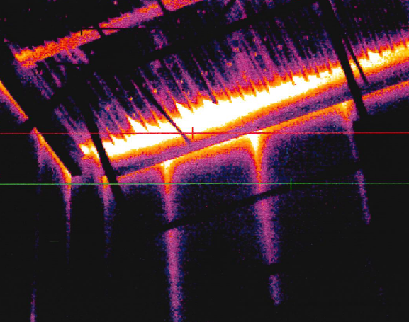
PHOTO 2: Shown is a screen capture of an infrared image looking up at the underside of a metal roof deck where the roof meets the walls.
For cold storage buildings, much of this discussion manifests itself at the roof-to-wall intersection around the entire perimeter of the building. Consistent detailing of the control layers around the entire building enclosure is needed for long-term performance and proper installation. However, designers must consider that some deck types (e.g., steel decks) have different profiles/terminations that need to interact with the wall. Steel decks have open flutes that abut/meet the wall on two sides, while the other two sides, due to the profile of the steel deck, abut with a solid profile. Each requires different emphasis during construction to prevent unwanted airflow within the deck itself. The "Details" section of this article provides more information.
Concepts for the Design of Cold Storage Buildings
A cold storage building should have building enclosure with these attributes:
- Adequate amounts of insulation and an appropriate attachment method to maintain interior temperature and minimize thermal loss.
- Compensation for thermal expansion and contraction.
- Control of air- and water-vapor movement.
There are three conceptual methods for the design of a cold storage building:
- Exterior envelope system
- Interior envelope system
- Building-in-a-building system
Exterior Envelope System Method
This method entails a vapor-retarder system located on the exterior side of the building’s structural system. The vapor-retarder system “encapsulates” the building by being located on the outside of the exterior walls’ insulation layer, under the floor and over the roof’s insulation layer.
Interior Envelope System Method
This method entails a vapor-retarder system located on the interior side of the structural system. In this scenario, the vapor-retarder system is located under the roof deck, inside the exterior walls and above the floor.
Building in a Building
This method entails constructing a cold storage structure within a building’s enclosure. The insulation and vapor-retarder system then may be applied to the outside of the inner structure’s envelope. See Figure 4 for a conceptual depiction of this method. With this solution, the outer building envelope structure provides a more constant temperature around the cold storage structure and eliminates exposure to the sun’s heat. It should be noted that the roof system on the outer building is not to be considered a “roof over a cold storage building” because the interior space beneath it is normally conditioned.
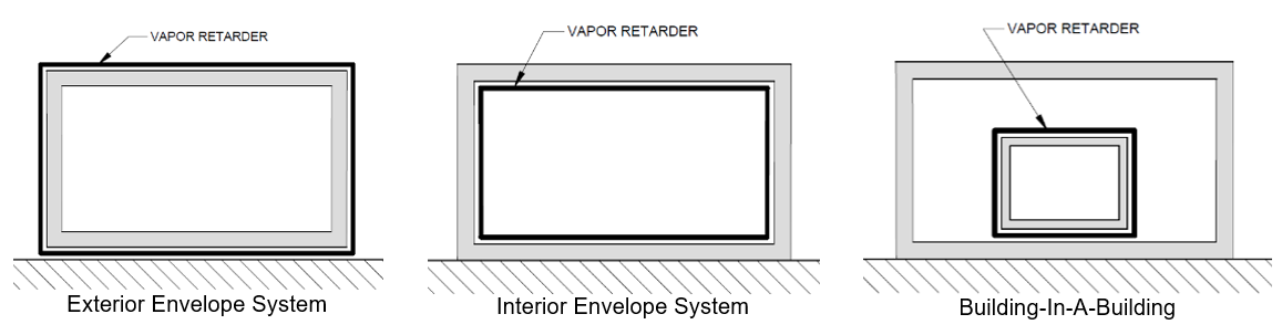
FIGURE 4: Shown are three conceptual methods for the design of a cold storage building.
The most common way to achieve these objectives is to use the exterior envelope system (EES). The EES method uses a vapor retarder that is located on the exterior side of the building’s structural system, which is commonly the roof membrane. More specifically, the vapor retarder encapsulates the building and is located over the roof’s insulation layer, on the outside of the exterior wall’s insulation layer and under the floor. This article focuses on the EES method.
Cold Storage Design Considerations
The design and construction of cold storage buildings requires attention to the following considerations:
- Building location
- Design values
- Roof insulation
- Thermal shorts/thermal bridging
- Expansion and contraction
- Air leakage and water-vapor movement
- Vapor-retarder perm ratings
Building Location
In warm climates (e.g., Dallas), the prevailing vapor-drive direction is inward, and therefore, the most effective location for a vapor retarder/air barrier is on the outside of the roof insulation. In most cases, the roof membrane will be the vapor retarder.
In moderate climates (e.g., Nashville and Kansas City), the vapor drive may be in either direction, and the location of the vapor retarder/air barrier depends on the predominant direction of the vapor drive. However, because there is generally more total moisture in the air during the summer months (versus winter months), the predominant vapor drive is into the building. Again, the roof membrane will be the vapor retarder.
In cold climates (e.g., Buffalo), the vapor drive will be reversed when the outside temperature is colder than the interior temperature, but there is less concern with condensation issues because cold air has a relatively small amount of moisture; and because the temperatures are often similar, vapor drive is less significant. Although, in cold climates, the interior may still be colder than the exterior (particularly where there is a blast freezer) and therefore, the most effective location for a vapor retarder/ air barrier is on the outside of the roof insulation. In this case, the vapor retarder will be the roof membrane.
Notice