Moisture Durability, Roofing and Green Standards


Part 2—Complexity
ENERGY EFFICIENCY IS A MOVING TARGET
The minimum or baseline energy efficiency in the code requirements and owner’s performance expectations have been a moving target over time. The cost-effective and validated energy savings has increased in each of ANSI/ASHRAE/IES Standard 90.1 (ASHRAE 90.1) three-year publications, which is one of the underlying national energy standards.3 The ASHRAE 90.1—2019 version was validated by the Pacific Northwest National Laboratory as an additional 5 percent of savings over the previous 2016 version.17
Compounding the energy savings, green building rating systems generally require additional savings beyond the baseline and provide points for exceeding the baseline. In addition, the energy performance requirements within green certification systems are also improving. As an example highlighted in Figure 2, the same energy savings that would have contributed 10 points to the LEED v3 rating system is roughly equivalent to the starting energy savings required in LEED v4.1, which is in the pilot phase13 at the time this article was published. Not every local jurisdiction adopts the same base model codes and standards at the same time and rate, which leads to additional confusion in the design and construction industry.
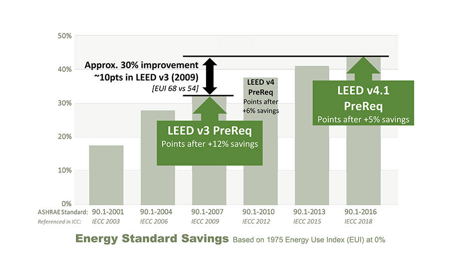
Figure 2. Increasing efficiency requirements are compounded by green rating systems.3, 7
INTERACTIVE COMPLEXITY AND TIGHT COUPLING
The book Normal Accidents by Charles Perrow explains how significant technological advancement can lead to failures.16 Perrow describes two main components of “normal accidents.” The first component being “interactive complexity” as a function of the number and degree of system interrelationships; when this factor is high… surprises are to be expected. The second component is “tight coupling,” the degree at which initial failures can concatenate rapidly to bring down other parts of the system; the more highly-linked… surprises are not easily isolated and resolved. If a system has only one of the two components then it is still a risk, but is more easily managed. When “interactive complexity” and “tight coupling” are combined, accidents could be considered “normal” or expected according to Perrow.
As more materials and additional requirements are added to enclosures, it is important to recognize when materials and assemblies need to change in order to achieve higher energy performance. In a broad sense, as energy efficiency is improved in building enclosures, moisture risks can increase from decreased heat flow across the assemblies, as shown in Figure 3. The changes in enclosures can manifest as generally lower exterior surface temperatures (during heating months) as the exterior is less dependent on the interior space conditioning. As we improve energy efficiency, we may also be increasing moisture risks in building enclosures. And the increased risk of “normal accidents” may result from more complex designs that are more tightly coupled to the building’s HVAC operations, structural elements, and occupant-use conditions.
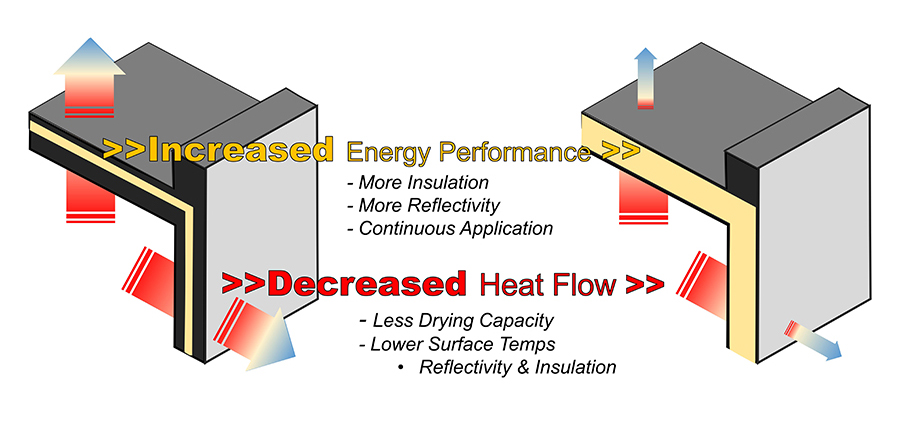
Figure 3. Energy efficiency improvements can lead to increased moisture risks in a building enclosure.
Consider the following real-world example of the “normal accidents” concept in practice and how it relates to a client’s awareness of or willingness to accept this risk for an innovative building. This relevant example comes from the first-ever LEED platinum building and a recently closed legal case.14 The example demonstrates the building enclosure’s technical complexity and tight coupling across various building systems. In the court’s findings, the decision lays out the framework mirrored in Normal Accidents stating “the inappropriate use of Parallams as structural support without proper weather protection”—it’s a complex system—and “these beams would have failed… well before they got around to doing any remedial measures at all.”—the systems are tightly coupled.
The concept of predictable outcomes from Perrow’s book makes sense in theory, but in practice, it can be complicated as this case demonstrates. Such case studies help bring awareness to potential issues and highlight the importance of establishing processes to manage the unanticipated moisture risks as early as possible. It is important through this green rating system assessment to recognize the options and limitations that exist with the rating systems and their actual coverage to mitigate moisture risks in the face of complexity and system coupling.
COMPLEXITY AND COUPLING IN ROOFING
In the article “Structural Concrete Decks, Vapor Retarders and Moisture—Rethinking What We Know” in the February 2020 issue of IIBEC Interface,20 the authors provide a clear example of how increasingly complex structural systems can have detrimental effects on the interconnected performance of traditional roof system.If a roof designer is worried about interior moisture vapor drive impacting a low-slope roof system, a traditional rule-of-thumb would be to add a self-adhered vapor barrier to the roof deck, prior to installing the roof insulation and membrane. But what if changes to the roof structure greatly increase the risk of adhesive failures that lead to assembly failure in these systems? As the authors of the IIBEC Interface article note:
- “The concept of cost of failure is critical to understanding the potential magnitude of the issue… if a concrete deck does not dry or retains moisture and the [rule of thumb] solution to address this condition does not work, the cost of failure is generally high.”
The authors identify the causes of the increased moisture risk over the last 30 years in roof systems come from two key changes in roof structural design. The first is the increased use of non-removable forms or composite steel and concrete decks. These decks allow for much shorter construction timelines, eliminating much of the expense of building and stripping temporary form structures, and are very structurally efficient. But by leaving the steel formwork in place at the bottom of the concrete slab, the concrete mix water has limited opportunities to dry out after the curing process is complete.
The second key change in roof structural design is the increased prevalence of lightweight aggregates in the concrete mix of roof slabs. Originally thought to only be a problem with lightweight structural concrete, recent research also raises concerns with moisture migration from normal weight concrete decks as well.21 The authors describe the added complexity:
-
”The use of lightweight aggregate that can hold more initial water than traditional ‘hard rock’ aggregate, combined with the use of metal forms that are left in place, has resulted in a significant likelihood of having to deal with what should be considered a ‘wet deck.’”
With both of these added complexities to the roof structure, non-removable forms and lightweight aggregate, the moisture retained in the concrete creates a new challenge that needs to be addressed to ensure the installed roof system will perform. Specifically, the logistics of applying a self-adhered vapor barrier to a “wet deck” are very problematic. It is unlikely that the bond would be sufficient over time as the moisture migrates out of the roof concrete slab over a period of years. To make matters worse, often subsequent layers of roof insulation and roof membrane are also adhered together, relying on the initial self-adhered vapor barrier’s bond to the “wet deck” to attach the entire roof system.
Due to the added complexity of the structural design and the interconnectivity of the structural system and the roof assembly, the authors state, “the standard of care may not be enough.” They go on to provide six alternate design configurations and attachment methods to navigate various scenarios and the attachments, assembly layers, and the fundamental physics that are at work across the interconnected structure and roof systems. Figure 4 is an example of one of the scenarios provided, with the non-traditional design elements highlighted in red for clarity.
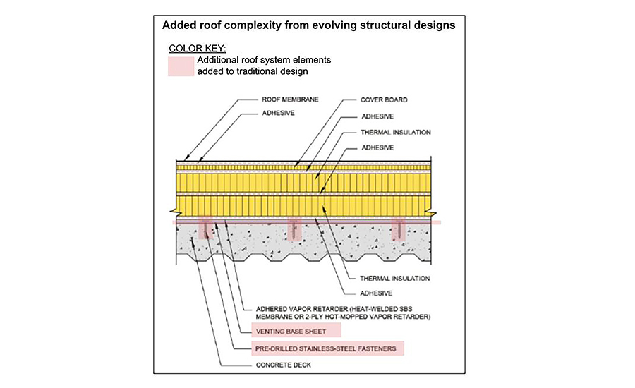
Figure 4. Example of added roof complexity from evolving structural designs.
This example demonstrates the challenges of seemingly small and incremental changes in complexity that can have a dramatic impact on interconnected systems, like concrete structures and roofing assemblies. The first challenge for designers is to recognize that the increased risk of moisture exists when designing roof systems with potentially “wet decks.” After identifying the increased risk, the design should be detailed to manage the potential for moisture from the concrete and/or decouple the concrete structure and roof system.
Notice


