At the Roof Edge: Water, Air, Thermal, and Vapor Control


Control Layer Summary
Discussing control layers as they apply to a roof or wall alone is fairly manageable. But the process gets much more complicated when the roof meets the wall at the parapet condition, and even at a flush edge condition. The “pen test” is relatively easy in theory, but it can get complicated as we zoom in and consider the control layers at each condition, penetration and transition.
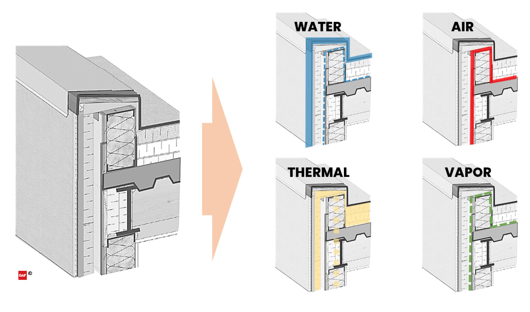
Example of breaking down a parapet detail by the four control layers.
In summary, the following are key points to maintain continuity of the control layers:
- Water Control is managed by the roof membrane and the cladding. A secondary water control layer is often found against the structure, behind or below the exterior insulation.
- Air Control can be managed at the deck level of the roof, which more readily can be married into the wall air barrier. The roof membrane can also be used as an air barrier as long as the detailing and transitions are done carefully.
- Thermal Control continuity is maintained by connecting the roof and wall insulation, which can be challenging. It’s important to be mindful of cavity insulation and the potential design risks of condensation at the thermal bridges.
- Vapor Control can also be in the same plane as the air control layer, based on location needs, construction methodologies and occupant use of the building.
Code References for Parapets
This section will make reference to the following national model codes and standards: 2018 International Building Code (IBC), the 2018 International Energy Efficiency Code (IECC), and the ANSI/ASHRAE/IES Standard 90.1-2016 (ASHRAE 90.1). It is worth noting that the summary provided below is not an exhaustive list of requirements for exterior wall and roof systems in the referenced national model building and energy codes. Different versions of the referenced codes have additional and/or different requirements; these requirements may also vary by adoption and modification by the local authority having jurisdiction. It is important to refer to local codes for the applicable requirements.
The requirements for parapets generally come from the building code (IBC) and the energy code (IECC and ASHRAE 90.1). The requirements within the building and energy codes can be mandated prescriptively, as a performance threshold, or by reference through specific key standards. The performance standards are important because they don’t attempt to regulate by providing exhaustive lists and itemized component requirements, like a prescriptive method. These performance requirements establish the design benchmark and then provide a methodology to demonstrate compliance with the benchmark.
The building codes and standards do not always address parapets exclusively, but many refer to “Exterior Walls” separately from “Roof Assemblies.”
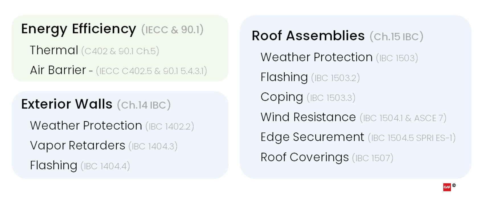
Summarized applicable code references for parapets.
Exterior Envelope in the Building Code
The exterior wall requirements for parapets are covered in Chapter 14 of the IBC which addresses “exterior walls, wall coverings and components.” For parapets, the requirements for weather protection, water-resistive barriers (WRBs), managing vapor and flashing apply as they do for the rest of the exterior building walls.
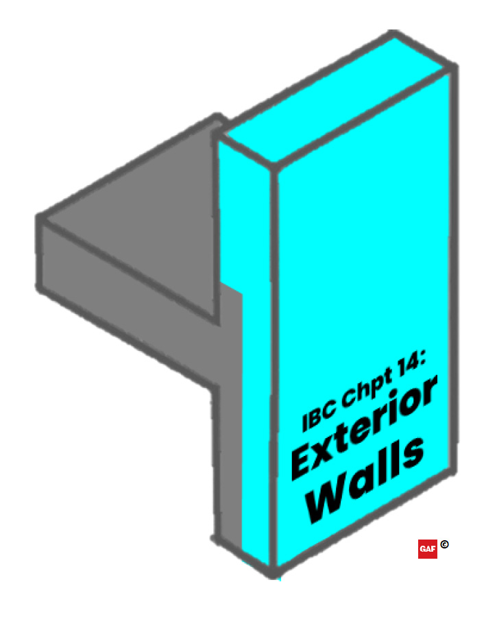
IBC Chapter 14: Exterior Wall applicable area highlighted in blue.
The roofing portion for parapets is covered in Chapter 15 of the IBC which addresses roof assemblies, specifically the “design, materials, construction and quality” of roofs. Regarding parapets, the roof system requirements impact the wall where terminations and transitions occur. The requirements include weather protection, flashing, coping, wind resistance design, edge securement and specific requirements for various types of roof coverings.
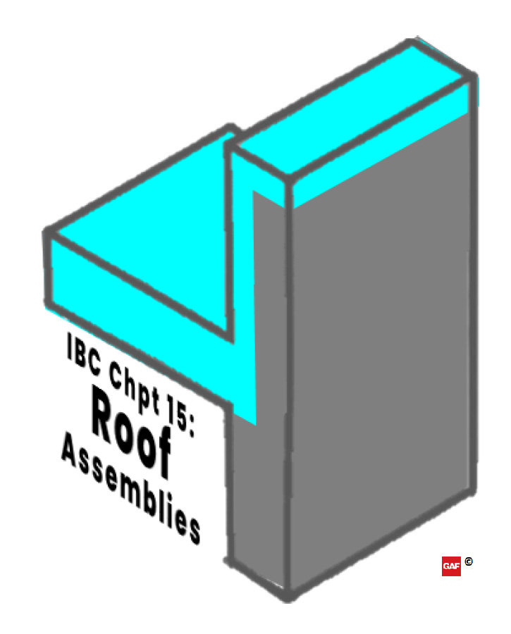
IBC Chapter 15: Roof assembly applicable area highlighted in blue.
Roof Assembly Weather Protection: The requirements for weather protection (IBC 1503) are fairly broad, requiring roof decks covered with approved roof coverings. Much more detail is covered in the additional IBC sections regarding roofing and parapets. In the roofing provisions, it is important to note that compliance with “the manufacturer’s approved instructions” doesn’t just affect a project’s eligibility for warranty, but is also required for building code compliance.
Roof Assembly Flashing: The requirements for flashing (IBC 1503.2) are repeated in part across the wall and roof portions of the code. This repetition highlights the importance of managing water control at the transitions. The code requirements for both roofs and walls support the water control layer principles in the pen test discussed previously. The roofing chapter in the code also directly mentions the parapet walls as a critical location for both roof system transition flashing and requirements for copings. While not an exhaustive list, IBC 1503.2 includes a minimum list of areas requiring roof flashing. These are summarized below:
- Flashing joints in copings
- At moisture-permeable materials
- At intersections with parapet walls
- At other penetrations through the roof plane
Roof Assembly Coping: The roof requirements for parapet wall copings are spread across many categories. One section specific to copings (IBC 1503.3) has a limited scope, requiring materials to be limited to “noncombustible, weatherproof materials” and be installed with a “width not less than the thickness of the parapet wall.” Many other requirements in the code also apply to copings in the code, such as flashing, wind design loads and edge securement performance. More will be discussed about copings in those sections.
Roof Wind Resistance: The wind resistance for low-slope commercial roof decks and roof coverings (IBC 1504.1) is required to be designed in accordance with IBC 1609.5, which ultimately leads to utilizing ASCE 7 for determining design wind loads. There are numerous updates to ASCE 7—2005, 2010 or 2016—and each has its own nuance as to how it impacts roof design loads.3 Because ASCE 7 is a performance standard, it is possible to use a version with higher performance requirements because designs do not need to be the minimum allowance.
ASCE 7-16 design wind loads are generally increasing relative to ASCE 7-10. In a recent blog article that reviews the analysis of two buildings of different sizes in two different cities, the author illustrates that design wind loads are reduced in Roof Zone 1' while Roof Zones 1, 2, and 3 have increased design wind loads. Roof Zone 1 percent increases are greatest while Roof Zone 3 increases are smallest. The increases in Pressure Coefficients from ASCE 7-10 to 7-16 are, in fact, relatively indicative of the increases in the design wind loads.
The methodology for determining the size of the perimeter and corner roof zones has also changed significantly in the new ASCE 7-16 version, resulting in larger roof areas contained by the perimeter and corner roof zones. Increased wind loads and larger perimeter and corner roof zones means that a greater area of the roof requires a higher capacity roof system and inherently more fasteners are used to secure the roof to the building. The referenced blog article provides an example where a 5-story building in Kansas City, Mo. requires nearly the entire roof system to have a higher capacity when calculating design wind loads using ASCE 7-16 vs. ASCE 7-10.
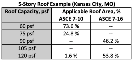
Chart showing required roof capacity and the roof area (%) where each is required.
Parapets are a combination of wall and roof pressures. The exact height of the parapet is not factored into the roof wind uplift calculations, but if the parapet is 3 inches or higher, the perimeter values can be used at the corners, lowering the uplift requirements for that portion of the roof area.
Continuing with the example 5-story building in Kansas City with the roof capacity shown in the table above, the use of a 3-inch continuous parapet would eliminate the need for the 120 psf capacity system and the entire roof could be designed and installed with a 90 psf capacity roof system. This approach would meet the code design requirements, simplify installation, and reduce the square foot cost of the roof, just by installing a 3-inch continuous parapet.
Parapets can help reduce wind uplift at the corners and perimeter.
Roof Edge Securement: Securing the edges on low-slope roofs (IBC 1504.5) has a significant impact on preventing failure and allowing the roof system to resist loads as it was designed. In addition to designing the wind resistance performance for the entire building (i.e., walls, roofs and parapets) per ASCE 7, metal roof edges are required to be tested for resistance in accordance with Test Methods RE-1, RE-2 and RE-3 of ANSI/SPRI ES-1. The referenced standard ANSI/SPRI ES-1 is a performance requirement that is specific to the strength of metal roof edges.4 ES-1 covers the “baseline” flush roof edge as well as parapet coping caps. When designing, it is important to specify compliance with ES-1 in the construction documents.
Roof Coverings: The IBC provides minimum installation criteria (IBC 1507) for various roof systems, based specifically on the attributes of that roof covering. In addition to the prescriptive criteria listed within, the IBC also mandates that “roof coverings shall be applied in accordance with the… manufacturer’s installation instructions.” Generally, the content of these roof covering sections address minimum substrate requirements, minimum roof slope, ballast requirements, and relative ASTM references to material standards, such as D6878 Standard Specification for Thermoplastic Polyolefin (TPO) Based Sheet Roofing.
Notice


