All of the Above: Unburdening Overburden Considerations for Commercial Roofing


Another consideration for overburden systems is the location of the insulation. For typical assemblies, the insulation is between the membrane and the deck and therefore not exposed to UV, water, or chemicals. Polyiso, EPS, and XPS may all be used in standard roofing assemblies, however, in an IRMA assembly, there are additional considerations. In an IRMA assembly, the insulation will be covered by a filter fabric and then covered with the overburden, such as vegetation. The insulation will need to have low water absorption qualities as well as high compressive strength. XPS and EPS are suitable in IRMA applications.
Where the membrane is the outermost layer, layers of rigid insulation are typically installed directly on the structural deck, and the membrane is subsequently installed on the insulation. The orientation of the boards during installation can play a significant role in energy efficiency in the assembly. During installation, insulation boards should be installed so that the joints are staggered and offset, and several layers of insulation should be installed rather than just one thick layer. Any gaps between boards can decrease insulating ability by allowing thermal loss, an increased condensation potential if air travels into the roof assembly. Air often brings moisture, which if allowed to condense within the insulation, can saturate the insulation boards. Wet insulation has an R-value of approximately zero, which is like having no insulation at all.
Lightweight insulating concrete (LWIC) is an alternate type of insulation where EPS boards are encapsulated in a slurry coat of insulating concrete, then the membrane, and overburden would be placed on top of the LWIC. The R value of the system and overall thickness are tailored to each unique project. LWIC can be advantageous for use in overburden installations because a desired slope can be achieved with the LWIC system and it has a high compressive strength. There are also no gaps within the installation, such as between standard insulation boards, and fasteners are not required to attach the LWIC, so there is limited thermal and air loss within the system.
While perhaps the most important criteria is insulating ability, mitigation of air infiltration is equally important. When warm outside air meets with cold inside air, condensation can form within the roof assembly which can reduce the roof insulating value or cause microbial growth. Proper installation of the insulation is critical to mitigate heat and air flow. The insulation should be installed in a minimum of two layers, and the joints in the top layer should be offset from the joints in the underlying layer. The edges of adjacent boards should be in contact to limit gaps between boards. Air and heat that is able to travel between gaps in the board results in energy loss.
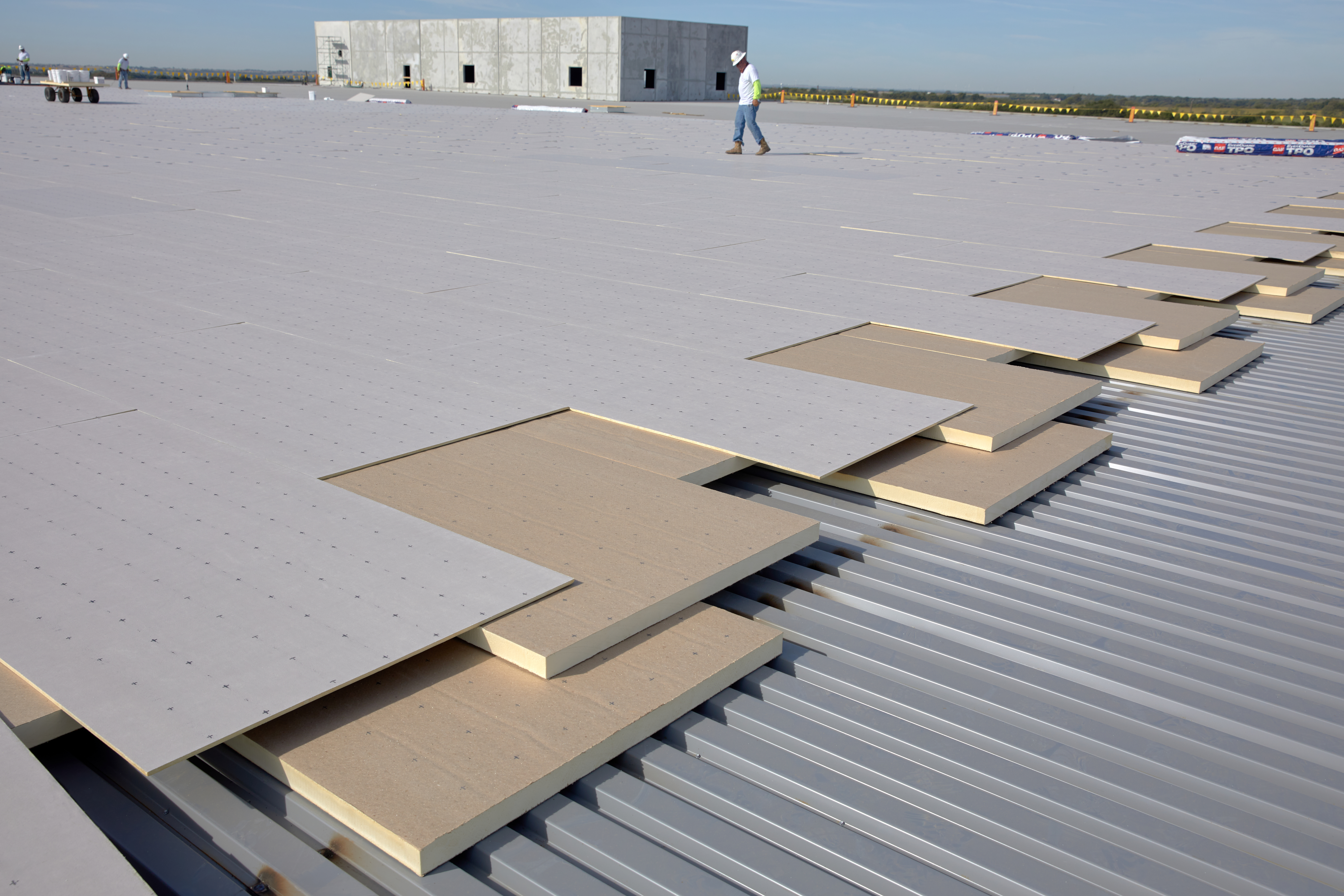
Photo courtesy of GAF
Staggered and offset insulation board joints.
Coverboards
Roof durability is system dependent and the entire roof assembly, including the inclusion of a coverboard, must be considered after selection of the overburden. Rooftops with overburden assemblies not only have more trades and increased foot traffic on the roof, but the overburden systems are an added dead load on the roof assembly. As with any roofing assembly, high traffic areas should be protected with walkway pads. Walkway pads, also sold in roll form, should be installed at roof access areas, such as hatches, around equipment, at overburden perimeters and locations where it may be accessed for service or maintenance. Walkway pads protect against abrasion and wear, but do not add compressive strength to the overall roofing system. The addition of a high-compressive-strength cover board below the roof membrane will enhance system protection, including compressive strength. Cover boards can help provide added protection against penetration by objects, including tools dropped by service contractors, wind-borne debris, and hail. Increasing the thickness of the cover board will increase its penetration resistance.
Typical coverboard materials are high-density polyiso insulation (HD polyiso) and gypsum. High-density polyiso is a high-density version of the traditional polyiso insulation. A ½-inch HD polyiso coverboard weighs 0.3 psf. The advantage of using HD polyiso is that it not only adds protection to the roof assembly, but it also adds an R value of 2.5 per half-inch. Typical gypsum coverboards, with an equivalent ½-inch board, weigh 2.76 psf and contribute an R-value of 0.5 per 1/2-inch.
Roof Installation Considerations
While the installation of overburden can contribute to sustainability goals of the building, ensuring a proper installation is critical to the long-term success of the roofing assembly. While the overburden itself can add to the energy savings and water retention of the building, the functionality of the roof is paramount. Tying in the overburden design to the overall roofing assembly design, down to the last detail, is critical. After the roof assembly and overburden has been decided, the roof details must be meticulously planned to include considerations for curbs, penetrations, flashings and review of the control layers to include water, thermal, air and vapor. The idea (and also code requirement) is that the control layers are continuous from the roof to the exterior walls. This prevents gaps in the system that can allow for water leaks or thermal breaks that may create locations of energy loss. Additional considerations to fire, wind and weight of the system must all be taken into account.
Image courtesy of Buildings
Figure 15: Risk elements for blue and blue-green roofs.
Control Layers
Parapet and wall construction types for each unique construction require project specific detailing. While the main function of the roof is to prevent water intrusion, the roof can also play a role in energy efficiency. Continuous control of air, thermal, and vapor throughout the building enclosure can have profound impacts on the long-term performance of the assembly. A design professional should review each roof assembly to determine the individual components and details required for continuity.
The water control layer, which is the primary function of the roof, is controlled by the roof membrane. The roof membrane should be detailed so that it is continuous over the edge of the roof (inclusive of the parapet if there is one), and tied-into the water-resistive barrier behind the exterior cladding. Gaps in the water control layer can lead to leaks within the roof assembly as well as at the interior of the building.
According to the U.S. Energy Information Administration, approximately 18 percent of all energy consumed in the United States in 2020 was attributed to commercial buildings; according to research completed by Canada’s Building Efficiency Technology Access Centre, air leakage is responsible for approximately 15-35 percent of a building’s energy consumption. Air leakage, where associated with the roof, can lead to condensation within the roof assembly, interior drafts, or simply, loss of conditioned air. Independent of the overburden, air leakage from the roof is controlled by ensuring a continuous air barrier from the roof to the walls. Air leakage is often controlled by the roof membrane, which can function as an air barrier, however, ensuring the roof membrane is tied-into the exterior walls is a detail that is often overlooked. If a vapor retarder is included in the roof assembly, the vapor retarder typically functions as the air control layer.
Thermal bridging, as it relates to roof insulation, is where the insulation is interrupted and allows for heat loss within a building. A critical detailing location for thermal bridging occurs at the roof to wall edge or parapet wall interface. “In current IECC and ASHRAE 90.1 national model commercial energy codes, the basic prescriptive requirements for both walls and roof systems include the use of continuous insulation in many climate zones and construction types. Continuous insulation is more effective than parapet cavity insulation, which is tucked into the voids between framing members. In parapets, the framing members are exposed to exterior conditions on both sides of the wall, rendering cavity insulation highly ineffective. At the intersection of the roof edge and parapets, maintaining continuity of the "continuous insulation" can be difficult as it is often disrupted by wood blocking or structural elements.”27
The vapor control layer, while an important part of the assembly, is possibly the trickiest layer, since a dedicated vapor control, or a vapor retarder, is not always necessary within an assembly. While some scenarios, such as the presence of a concrete roof deck where a vapor retarder is recommended, in an assembly with a steel deck, the presence of a vapor retarder may cause moisture problems by trapping moisture within the roof assembly. Vapor transported moisture can result in condensation within the roof assembly. A hygrothermal analysis or dew point analysis is generally recommended to determine where the condensation point will occur in an assembly; the analysis will determine if a vapor retarder is required. As part of the analysis, it is important to determine the direction of vapor drive, which is from warm to cold. For a typical building, the direction of vapor drive may change throughout the year depending on interior and exterior temperatures. Condensation may occur only during certain times of the year or in certain conditions. It is important to note that roof membranes are generally impermeable to vapor, and in most cases, provide adequate defense against vapor intrusion. The presence of a vapor retarding roof membrane may be all that is required in most assemblies.
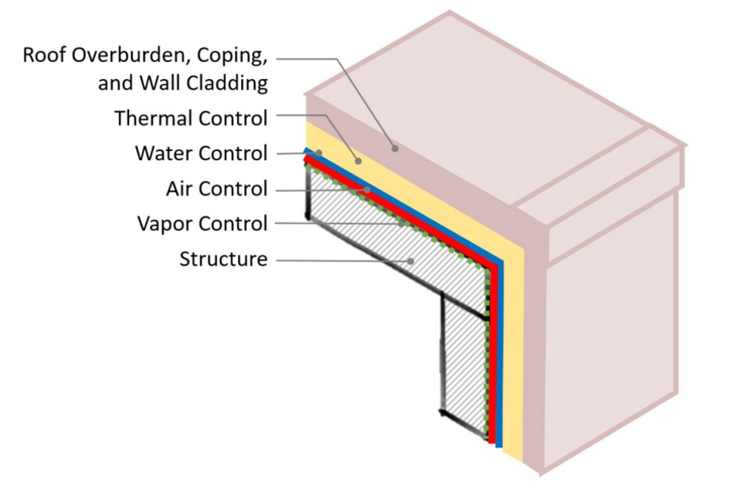
Figure 16: Simplified version of continuity of control layers from a roof to wall.
Overburden Layout, Details & Flashings
Qualified design and construction professionals must be integrally involved through the design and construction of both the roof and the overburden systems. The layout of the overburden should address access for initial overburden installation and both roof and overburden maintenance throughout the service lives of the components.
Adequate flashings and terminations of the roof membrane are arguably the most important part of any roof assembly. Inadequate detailing or termination heights leave the roof assembly vulnerable to water infiltration. Best practice dictates that the number of roof penetrations are kept to a minimum, which is not always possible. Maintaining flashing heights and detailing per manufacturer’s recommendations are crucial for a water-tight system. Inadequately detailed or flashed components may be water-tight for a period of time, but will most likely fail prematurely. Repairs can be costly at best, but removal of the overburden systems for the associated repairs can be an added difficulty and cost. In general, it is good practice to allow penetrations, flashings, expansion joints, drains, and other critical roofing interfaces to be accessible for maintenance and repairs.
For a typical roof assembly where the membrane is at the top of the assembly, NRCA recommends the height of the base flashing to be a minimum of 8 inches above the surface of the roof. For vegetative systems, the height of the base flashing should be a minimum of 8 inches above the surface of the growing medium. The use of couterflashings is recommended so that the base flashings are protected from UV exposure and physical damage. This is also best practice for limiting the scope of roof replacements. Flashings should be installed in accordance with current NRCA guidelines or the roof manufacturer’s construction details.
Movement of building elements should be anticipated and the placement of expansion joints at critical interfaces should be evaluated. In addition, the interaction between the overburden systems and the expansion joints must be explored. In general, it is recommended that the overburden systems do not cross or cover expansion joints.
While some roofing manufacturers do not exclude ponding on roof surfaces, it is a best practice to maximize drainage and remove ponding water within 24-48 hours. Ponding, solely as water, may not be detrimental to the roof’s surface, but ponding often holds debris, chemicals, and other deleterious substances, which can increase the rate of deterioration of the membrane. Ponding water also is also extremely heavy, and 1-inch of water can add 10 lbs/sf to the structural loading of the roof.
Overburden systems should be designed and installed so that they do not inhibit drainage of the roof. Particularly for solar arrays or tray vegetative roof systems covering large areas of the roof, drainage requires special consideration. Ballasted assemblies can block or inhibit drainage, which can result in trapped water on the roof membrane. The overburden layout design should also consider how the drains will be accessed for maintenance. Overburden systems that cover drains may allow for drainage, but may be near impossible to locate for maintenance and inspections. If possible, the layout should leave portions of the roof around drains open and unimpeded by the overburden.
Codes & Standards
The designer of record will determine which codes and standards will govern fire, wind, and structural considerations, generally starting with the International Building Code (IBC) and the referenced codes therein. In addition, the local Authority Having Jurisdiction (AHJ) should be consulted to determine the specific requirements for code compliance of the overburden systems.
Structural considerations for existing buildings during a retrofit scenario become extremely important, as the weight of each system must be analyzed. Solar panel weights vary from manufacturer (5 psf) and vegetative roof systems weight must be based on the saturated soil conditions, with extensive averaging 25 psf and intensive upwards of 100 psf. For blue with water retention, adding one-inch of water can add 10 psf to the roof dead loads, and purple-roof dead loads are the weight of the water plus the weight of the vegetation. Strengthening of existing structural building components may be difficult and expensive. For new buildings, the additional weight of the system can be taken into account with the original design, which offers the greatest potential for flexibility in design since the structure can initially be designed and installed to incorporate overburden.
Roof assembly wind design is mandated in IBC which references ASCE 7; roof wind uplift requirements will be based on individual building locations, wind speeds, building height, and other project specifics. However, there are no specific code or testing requirements for overburden on top of the roof. It is at the discretion of the overburden manufacturer’s (solar, vegetative, etc.) to determine whether their systems will withstand wind uplift for a particular location. As such, each individual manufacturer should be consulted during both the design and construction phase.
The International Fire Code (IFC) has provisions for Landscaped Roofs, Photovoltaic panels, and general roofing requirements. Requirements generally include clear paths to service equipment and other considerations to reduce roof fire hazards. It should be noted that the clear paths generally leave areas of the roof membrane exposed. Proper detailing of the exposed roof membrane should contain walkpads and protection as necessary to protect the membrane. The Landscaped Roofs provisions are located in Section 317 of the 2021 version of the IFC. The Code has provisions for maximum vegetative rooftop size (15,625 SF) and includes a maximum dimension of 125 feet for length or width and a clearance of 6 feet of listed Class A tested roof assembly between adjacent landscaped roof areas. A continuous border of 6 feet is also required around penthouses, solar panels, mechanical equipment, and other building service equipment to reduce fire hazards on the roof. Further guidance is provided for maintenance of the vegetation including irrigation and removal of dead foliage. The IFC has provisions for Solar, which is located in Section 1205 of the 2021 version of the Code. Solar photovoltaic systems require roof access, pathways, and spacing so that firefighters can access the roof. PV panels must allow a 6 foot perimeter pathway around the edges of the roof, and interior pathways must be provided at intervals not less than 150 feet throughout the length and width with additional requirements for standpipes and hatches.
Additional resources are available to include publications through NRCA (National Roofing Contractors Association), SMACNA (Sheet Metal and Air Conditioning Contractors’ National Association), ICC (International Code Council), ASCE (American Society of Civil Engineers) and ASTM (American Society for Testing and Materials).
Roof Systems Guarantees
The importance of matching the life expectancy of the roof and the overburden is critical since the cost of failure of the roof membrane can be high. Removal of the overburden is required for replacement of the roof assembly, which equates to loss of energy generation for solar arrays, potential expiration of vegetation, potential damage to aging solar arrays, and the added cost of overburden removal and storage during the process. In addition, at a minimum, the roof system must be designed such that the roof system guarantee will meet or exceed that of the overburden system.
Manufacturers typically do not guarantee overburden installations and the roof guarantee is only inclusive of the roof assembly. Therefore, most manufacturers specifically disclaim any liability arising out of or in connection with the integrity, installation or performance of, or damages sustained by or caused by the overburden systems.
Therefore the design of the roof assembly and the overburden, including NRCA and manufacturer's published specifications and details must be accepted by the manufacturer prior to overburden installation to avoid any lessening of coverage of the guarantee.
Emma Park Neighborhood Center
Photo courtesy of GAF
Emma Park Neighborhood Center TPO roof installed beneath vegetative roofing and solar panel installations.
Building Overview: Located in Butte, Mont., the Emma Park Neighborhood Center was built to accommodate programs to benefit poor and low-income households and serve as a social gathering place to help improve and rebuild the uptown area, which had fallen on hard times. The funding came largely from donations.
The Challenge: The roofing work needed to begin in January 2014, which can be a challenge in Butte, as it’s 5,300 feet above sea level. In previous years, they had seen record temperatures hit as low as -52F degrees. Luckily that year, 75 percent of daytime temperatures were above freezing.
Roof & Overburden System:The roof incorporated a white reflective TPO membrane over polyiso insulation with each section having a different overburden system. One section of the roof contained a vegetative roof, one contained an amenity deck, and one contained solar panels.
Notice