The Evolving Importance of Health Care Resiliency


HEALTH CARE APPLICATIONS POWER SYSTEMS: RESILIENCY, RELIABILITY, MAINTAINABILITY, AND SAFETY
The demand for reliable power systems in critical facilities continues to increase, putting pressure on engineers to design reliable systems within project budgets that are often decreasing. This article discusses some of the factors to be considered when designing systems for critical facilities and provides examples from a recent hospital design. The case study used throughout this article is for a new hospital that is approximately 1 million square feet in area.
The code requirements for essential power are focused on providing the minimum amount of emergency power to allow people to safely egress a facility. While this amount of emergency power meets the requirements for life safety, it’s often not sufficient for critical facilities that also need to maintain business continuity during an interruption of power. Power systems that cannot be interrupted during utility outages are important to maintaining safe operation of critical facilities and can also support ongoing maintenance activities. When designing normal and essential power systems for a new facility or upgrades to an existing facility, close attention must be given to resiliency, redundancy, and maintainability.
Resiliency
Resiliency can be defined as the ability of an electrical system to recover from a disruptive event that can put a stress on the system. The word “resilio” means to leap or spring back. Stress can vary by type and scale and often cannot be anticipated, but when a stress event occurs, the system must adapt and recover within a reasonable time frame based on a facility’s requirements. Some of the common incidents that cause stress to a power system are hurricanes, tornadoes, and flooding, and each of these may interrupt the power grid and disable the utility’s distribution system. Inside buildings, one major concern is flooding of normal and essential electrical distribution equipment, such as normal service switchgear, emergency generators, emergency switchgear, automatic transfer switches, and components of these systems.
Based on previous experience on the impact of buildings from stress events, the following recommendations for the design or upgrade of electrical systems in a critical facility have been developed:
- Install all major components of the normal and essential power systems above ground level to prevent flooding of the main distribution equipment and the emergency source of power. This includes normal switchgear, emergency generators, paralleling switchgear, automatic transfer switches, and main distribution panels. In addition to the location of the emergency generators, it’s critically important to consider the fuel delivery system, ensure pumps and tanks are located outside of potential flood zones, and that provisions are made to waterproof pumps and tanks to maintain operation in the event of a flood.
- Install equipment that meets local seismic requirements to be protected from power outages due to damage of electrical system components during an earthquake.
- Coordinate the installation of mechanical and electrical systems to prevent internal flooding of the electrical distribution system’s main components. For example, a leak in the boiler plant installed on a floor directly above an emergency electrical room may result in electrical system flooding and damage.
When installing electrical equipment above ground level, it’s important to consider the ongoing maintenance of the equipment. Service elevators, removable panels in walls, and designated equipment egress paths ensure that electrical equipment can be moved in and out of the electrical rooms.
Another way to increase electrical system resiliency is to install combined heat and power (CHP) systems. A CHP system, sized to meet the base load demands of the thermal system in the building, will usually produce electrical cost savings. CHP systems cannot be used as standby or emergency power systems, but when combined with on-site emergency generators, a CHP system often allows a facility to maintain some level of business continuity during a prolonged utility outage. True “island mode” may be possible, but it’s important for the facility to have a business continuity plan to ensure critical systems are maintained during one of these outages.
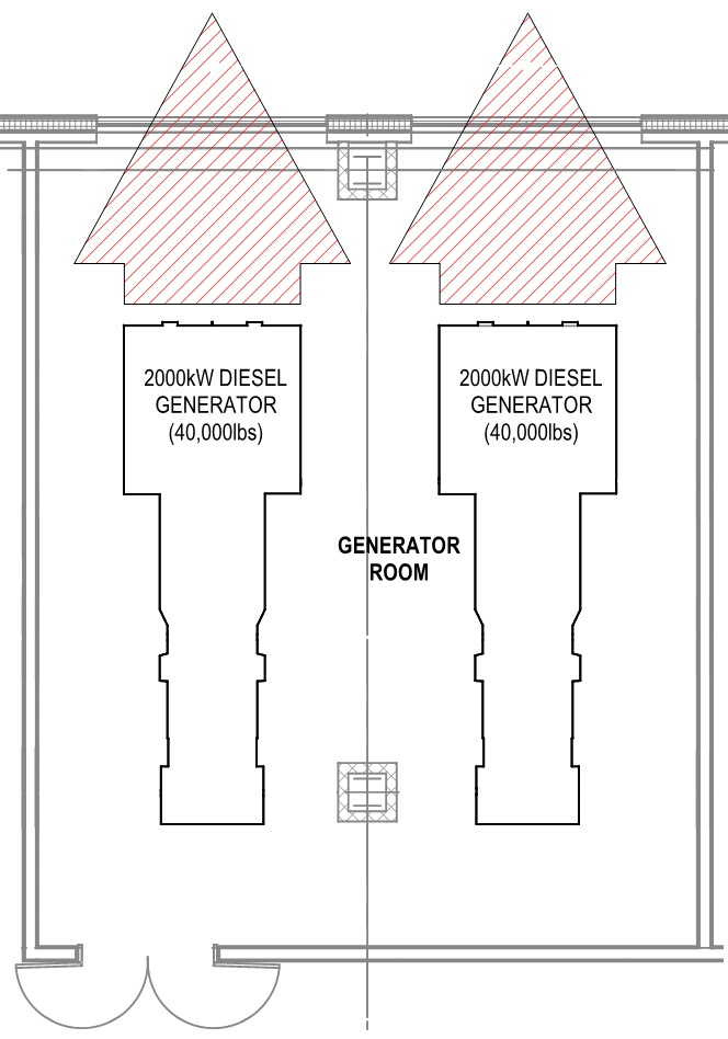
Image courtesy of SmithGroup
FIGURE 6. A generator removal plan using removable panels in an exterior wall.
New Jersey Hospital - Case Study
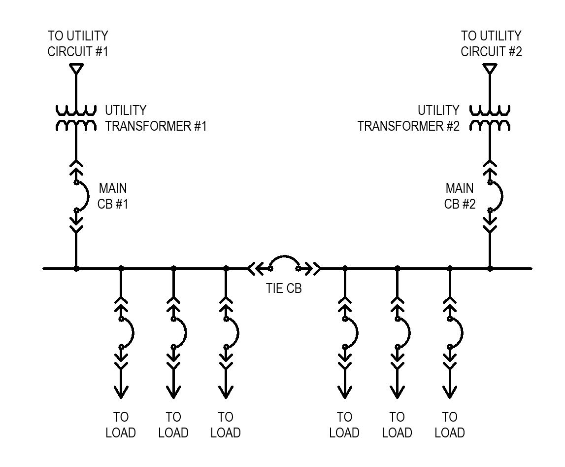
Image courtesy of SmithGroup
FIGURE 7. A one-line diagram of the main-tie-main service switchgear.
The main normal and emergency electrical rooms are located on the third floor of the hospital’s central utility plant, a floor above the major mechanical and plumbing equipment. That location makes the electrical systems more resilient to external hazards, such as natural flooding, and internal hazards, such as leaks in mechanical and plumbing equipment. A detailed egress path was developed for the electrical equipment, including removable panels in the external wall and properly sized freight elevators. This included an analysis of the structural system along the egress path to support the weight of the equipment. The design also includes provisions in the electrical and mechanical systems for a future CHP plant.
Redundancy and Reliability
Redundancy of systems is a primary strategy for improving the reliability of both the normal and essential power systems in a critical facility.
The reliability of power systems in a building begins with the utility and reliability of the power grid. For a critical building, it’s advantageous to have the utility provide more than one power feeder with each feeder originating from a separate utility substation. For hospitals, NFPA 99 recommends redundant utility feeds with an automatic transfer scheme between the feeders. This type of configuration provides protection against a failure in one of the utility substations.
Redundancy of normal power systems is often deployed in a “main-tie-main” configuration of the normal service switchgear, where each transformer is sized to carry the full electrical load of the switchgear lineup. The main and tie breakers in the switchgear are also sized to accommodate the full load. This configuration provides redundancy in the event that one of the transformers or incoming feeders fails. It also provides the facility with the ability to perform routine maintenance on the transformers and main breakers without interrupting power to the building.
N+1 redundancy is often employed to improve essential electrical system reliability. The N+1 term is used in a number of other MEP applications, including mechanical, plumbing, and information technology. As applied to the essential system, the letter “N” stands for the minimum required number of emergency generators to support facility operations, and “N+1” represents an additional generator that can allow continuity of operation in case of equipment failure or scheduled maintenance.
In hospitals, critical and life safety branches are required to restore operation within 10 seconds (NEC, 517.32.B). It is not reasonable to assume that multiple generators can start and parallel to a common bus within 10 seconds, so it’s a good engineering design practice to size emergency generators so that one generator is capable of supplying power for all life safety and critical loads. For example, if the life safety and critical load was 1,300 kW, then the base size of generator would be 1,500 kW. The generator plant would include one 1,500-kW generator for life safety and critical loads, one 1,500-kW generator for equipment loads, and one 1,500-kW generator to provide N+1 redundancy.
Installation of an exterior quick connect for a temporary generator was introduced in the NEC 2017 article 700.3. For instances with only one source of emergency power (i.e. one generator), a quick connect is required to provide emergency power for life safety loads during routine maintenance of the permanent emergency generator. Sizing the quick connect to support not only life safety but also critical branch loads is a good practice. In instances with parallel generators, a quick connect provides additional redundancy and resiliency to the power system but is not a code requirement.
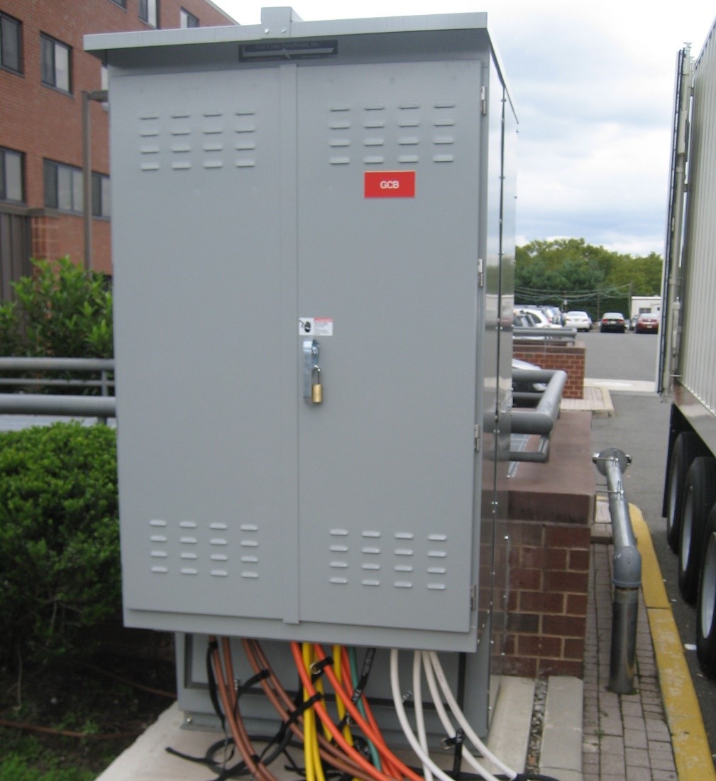
Image courtesy of SmithGroup
FIGURE 8. A temporary generator quick connect.
Further examples from the case study
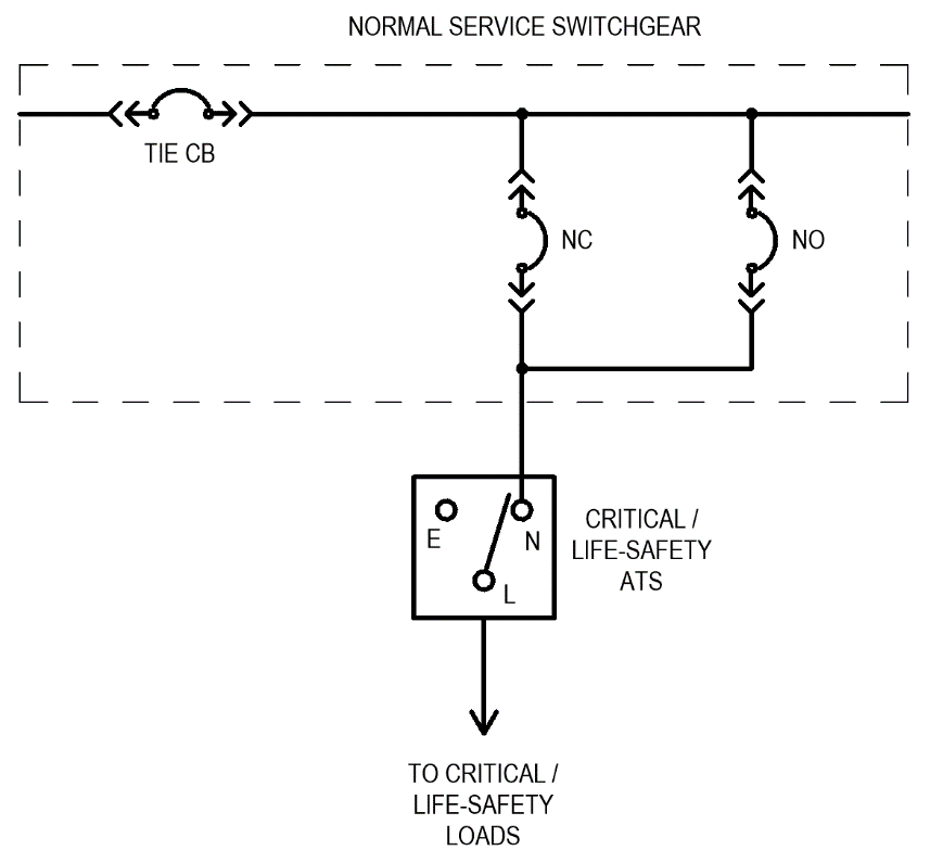
Image courtesy of SmithGroup
FIGURE 9. A one-line diagram of a redundant normal feed to critical and life safety loads.
All normal substations are designed as “main-tie-main” systems with transformers sized for full normal load. Substation transformers are fed from dedicated circuits connected to different buses of the medium-voltage outdoor utility switchgear that also has a main-tie-main configuration with a closed tie.
The essential electrical system originates at three emergency generators that connect to indoor paralleling switchgear with one provision for a future generator. A temporary generator quick connect is located outside of the central unit plant and is sized to support the life safety and critical loads of the entire campus.
Notice