Beyond Airtightness: Factors to Consider When Selecting an Air Barrier
Learning Objectives:
- Define the basic requirements that air barriers must meet.
- Describe the different types of air barriers on the market and their key differences.
- Identify key areas within a wall system where detailing is important to system success.
- Describe the different solutions currently on the market for sealing penetrations and transitions to create a complete air barrier system.
Credits:
There is no audio associated with this presentation. Additional slide information can be found in the “Notes” section of the presentation or download below.
The value of a product or application stems from not only its technical appropriateness, but also its ease of use and the confidence it instills in those who specify and those who do the actual application.
Not surprisingly, following a prescriptive path for compliance with energy code requirements in climate zones that necessitate a split-insulation strategy—a wall assembly with both cavity-filled insulation and continuous exterior insulation (CI)—will reveal vapor-permeable capabilities are key for wall assembly breathability and, by implication, for long-term durability.
In these climate zones, geographic regions often are encountered that have already become (or are now becoming) aware, through codification, of the need to include thermal control—particularly at interface locations—in addition to ensuring continuity of the air and water control layers. For years, the market has offered solutions limited to addressing a specific condition: typically a clear field, linear or single-point condition.
These individualistic solutions address specific performance or characteristic requirements for a particular interface or transition condition. When it comes to transitions and maintaining continuity of those same characteristics, there often are instances of incompatibility when material and component selection is not fully considered.
With the wide variety of air-barrier materials on the market, it is important to have an understanding of the available options and their general performance attributes and specific challenges, as well as to maintain a holistic perspective of how these materials will be anticipated to work together and perform.
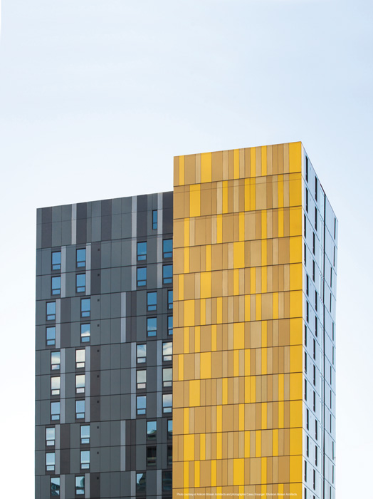
©Ankrom Moisan Architects; photographer: Casey Braunger
SHEET- VERSUS LIQUID-APPLIED BARRIERS
In the air-barrier arena, there have been longstanding discussions and philosophies regarding whether a fluid-applied barrier should be selected over a sheet-applied material. The options in both categories are numerous and diverse, as are the rationales for making such a decision.
Sheet-Applied Barriers
Choices in the sheet-applied category can be divided into two basic subcategories: mechanically attached or self-adhering. The challenges associated with mechanically attaching an air barrier include impact on performance and the ease of installation, which ultimately affects long-term durability.
Mechanical attachments—and the holes made in the air barrier during their installation process—represent a potential path for uncontrolled air and water infiltration. To function as a continuous air barrier (a requirement for optimal air-barrier performance and long-term durability), the lapped joints at the sheet material’s edges should be sealed—either taped or affixed with some form of a self-adhering backing. In both instances, one can readily imagine the challenges that either of those operations face on a breezy day. The self-adhered variety of air-barrier materials often comes in the form of an asphaltic-based sheet laminated to a high-density polyethylene (HDPE) or metalized liner. Typically, these materials require a primer to provide long-term adhesion, which adds labor, time and materials.
This is not to say installation of either type of the sheet-applied system cannot be done satisfactorily. However, they typically require more attention to detail and advanced knowledge and coordination of how the interface/transition conditions to adjacent systems (e.g., fenestration) will be managed. These transitions often require another suite of materials, which raises concerns related to sequencing, compatibility, adhesion, and movement capacity.
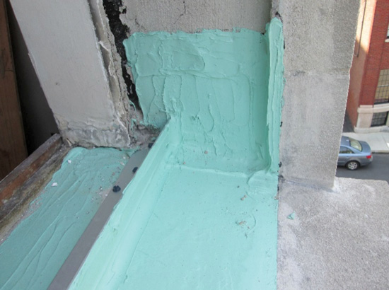
Photo courtesy of Simpson Gumpertz & Heger
Liquid flashing installation at window opening—single material and installation operation.
Fluid-Applied Barriers
Providing more flexibility in the types of substrates to which they can be applied, fluid-applied air barriers simplify installation on more complicated construction projects. For instance, a fluid-applied barrier would be ideal for a wall that transitions from a concrete knee-wall to a framed wall that then transitions (laterally) to a concrete masonry unit (CMU) wall—a combination readily found in commercial construction where the interior usage and associated wall types vary along a given elevation. In addition to the benefit of substrate compatibility, silicone liquid-applied air barriers—particularly those that are water-based—offer primerless adhesion to most construction substrates, minimizing labor and additional product costs within a low-volatile-organic-compound (low-VOC) formulation.
Liquid-applied barriers typically are segregated by thickness of application. Thick-mil systems use more material and have lower yields per gallon of material purchased—and hence are typically more expensive on a per-square-foot-installed basis. Moreover, achieving the required thickness is challenging, as the material can begin to slough during application if upper-end thickness is not monitored. Conversely, thin-mil systems leave little margin of error for the applicator and make it difficult to ensure sufficient material on the wall to provide long-term performance. Liquid-applied membranes in the range of 15-mil dry-film thickness (DFT) optimally provide sufficient material for uniform coverage and performance, while not risking sloughing of material due to high buildup during installation.
Additionally, some barrier products are marketed as having self-sealing properties, but without full consideration of fastener size, those claims may likely—and justifiably—be received with some doubt. A conversation with the air-barrier system manufacturer about the extent of fastener testing and studies would be advantageous.
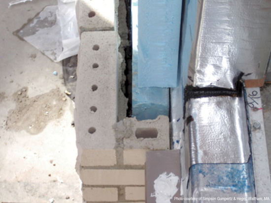
Photo courtesy of Dow Corning Corporation
Self-adhered membrane installation at window opening—multiple layers and sequencing implications.
ENERGY CODES AND AIR-BARRIER PERMEABILITY
If the exterior wall design calls for a fully continuous exterior insulated wall, the often-referred-to “perfect wall” provides an easy answer.1 However, the potential for higher costs associated with engineered solutions to provide both the necessary depth to accommodate insulation requirements and a robust secondary support system for the cladding to cover the insulation poses challenges to some projects.
Both the American Society of Heating, Refrigerating and Air-Conditioning Engineers (ASHRAE) 90.1-20132: Energy Standard for Buildings Except Low-Rise Residential Buildings, and the International Energy Conservation Code (IECC)3 mandate inclusion of continuous insulation. In these cases, the default choice becomes a design that includes stud-cavity-filled insulation along with the minimum-required CI. In these situations, air-barrier permeability (to ensure wall assembly breathability) and long-term durability are especially important considerations.
MODELING OF AIR-BARRIER PERMEABILITY REVEALS PERFORMANCE EFFECTS
Three diverse climate zones were examined to study the impact of air-barrier permeability on the whole wall assembly, factoring in the implications of energy code requirements on the wall assembly makeup and design. Individual climate zones and the prescriptively required CI for each of the selected climate zones are those defined in ASHRAE 90.1-2013. The study included locations in Miami, Florida; Seattle, Washington; and Chicago, Illinois—climate zones 1, 4, and 5, respectively.
Using WUFI® Pro 5.34 to conduct the hygrothermal analysis, a typical commercial building was modeled under typical (default) interior environmental conditions. The typical exterior wall assembly construction is as follows:
- Brick veneer with a 25 mm (1 inch) air cavity;
- Fiberglass-faced exterior gypsum sheathing;
- 150 mm (6 inch) steel studs with fiberglass insulation in the cavity;
- Interior gypsum board; and
- Acrylic paint interior finish.
For each of the respective climate zones, the air (or air-vapor control layer) was placed on the exterior surface of the exterior sheathing. For the purposes of this discussion, the air control layer is a vapor-permeable 100 percent silicone water-based fluid-applied product with a dry-/wet-cup United States perm rating of 10.1/26.6; the air-vapor control layer is a generic membrane with a U.S. perm rating of less than 1. Continuous exterior insulation, where required prescriptively by code, was modeled with the insulation placed over the air/air-vapor control layer.
In climate zones where a minimum provision of continuous exterior insulation is required for code compliance, hygrothermal analysis showed the breathability of wall assemblies—enabled by a vapor-permeable air barrier—helped reduce the moisture content level in the exterior sheathing over a three-year period. This is compared to the same simulation conducted substituting the permeable air barrier for a nonpermeable one. This phenomenon was observed to be more pronounced in those climate zones that required more continuous exterior insulation—in this case, Seattle (CZ4) and Chicago (CZ5).
All three climate-zone scenarios with the vapor-permeable air barrier showed a general drying trend of the wall assembly over the three-year simulation period. However, when the air barrier was replaced with the nonpermeable product, the wall’s drying potential appeared to diminish in all modeled climate zones. This trend was observed to be more pronounced progressing toward colder climate zones and as CI requirements also increased.
In the simulation for Miami (CZ1), there is no requirement for continuous exterior insulation, so the impact of a permeable or a nonpermeable air barrier is more subtle. For the most part, the condensation point (which is not the same as the dewpoint) occurs outside of the wall assembly and away from interior materials that may experience the deleterious effects of uncontrolled moisture (vapor) migration. Models did show a vapor-permeable solution allowed for more drying of the wall assembly over time. Given the warm, humid nature of the Miami environment, priority consideration for ensuring a quality installation for continuity throughout—particularly at wall penetrations and transition conditions—would be more beneficial.
Seattle (CZ4), being a more temperate location but seeing a higher level of precipitation in the winter, showed the permeable air-barrier solution being more favorable. Using the analogy of a high-performance rain jacket—one allowing the body to perspire and the moisture associated with the perspiration to exit through the jacket for improved comfort—the permeable air barrier permitted the bi-directional transmission of vapor (in both winter and summer conditions) and allowed the wall assembly to dry out and mitigate the accumulation of moisture content that might result in undesirable condensation within the wall assembly.
Modeling a prescriptively compliant wall assembly for permeable and nonpermeable barriers, the simulation showed an initial drying trend for both. However, over the following three winter cycles, the nonpermeable air-barrier assembly saw increased moisture content in the exterior gypsum sheathing and higher risk of condensation development at that same location. The permeable condition did not indicate an increase in moisture content.
The simulation results for Chicago (CZ5) were clearer in terms of the advantages of using a permeable air-barrier solution. When using the nonpermeable air barrier under winter boundary conditions, the simulation showed the split-insulated wall configuration did not provide sufficient thermal insulation to push the condensation point of the wall assembly to the exterior side of the air-vapor barrier. The results show after an initial drying period within the first few months of the simulation, the moisture content in the exterior sheathing saw a sixfold increase in moisture content in the winter months. This phenomenon repeated every winter over the three-year simulation period.
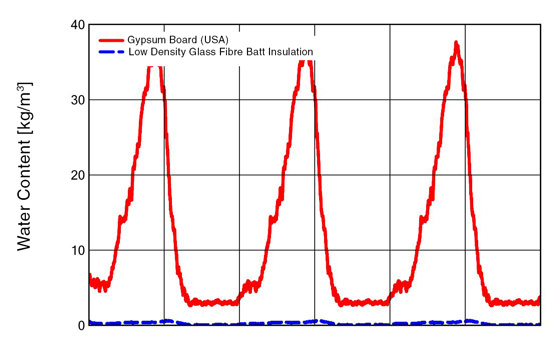
Image courtesy of Dow Corning Corporation
Water content in exterior sheathing with nonpermeable air barrier—Chicago (CZ5).
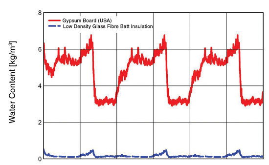
Image courtesy of Dow Corning Corporation
Moisture content of exterior sheathing with permeable air barrier—Chicago(CZ5).
In each of the aforementioned simulations, air-barrier breathability was found to be a factor in the increased long-term durability of the wall assembly. In simulations where the minimum-energy-code-required wall assembly (the hybrid insulated wall) was modeled, the use of a nonpermeable air barrier was shown to increase the risk of condensation development in the wall cavity. This potential can not only diminish the real performance of the wall, but it also may have significant impacts on the long-term durability of wall materials themselves.
Simulations show a vapor-permeable air barrier is the most technically flexible option.
BEYOND THE MATERIAL: A SYSTEM APPROACH
Taking a more holistic approach to wall assembly design and material selection brings into consideration other factors in the air-barrier system selection. Like water penetration resistance and thermal resistance, airtightness is only as good as the weakest link in the entire wall assembly. The migration of moisture vapor into a wall cavity is more evasive and damaging (by an order of magnitude) when accommodating full movement capacity than the effect of diffusion alone. The airtightness at these transitions often is more important than the airtightness and actual permeability of the air barrier itself.
By using a system-based air-barrier solution, many of these concerns can be addressed. Liquid-applied silicone air-barrier systems typically are easy to apply and come with a suite of compatible silicone-based accessories. Specifically, use of a compatible liquid flashing mitigates the infamous “origami” of sheet-based systems at window rough openings. Liquid flashing—particularly when used in situations permitting primerless installation—also represents a significant time-savings component in comparison to sheet-applied materials and even other liquid flashing materials that require an embedded mesh for reinforcement. Further, silicone transitions are readily available and do not have the concerns associated with acrylic- or asphaltic-based materials.
Additionally, system-based air-barrier solutions deliver simplicity for specifiers and project managers, easing the decision-making process. With the benefit of a single manufacturer of the barrier components, designers can be confident the system will collectively work for the wall assembly design without compatibility concerns, enabling flexibility in project sequencing. Moreover, availability of supplemental, fully compatible accessory materials adds additional flexibility.
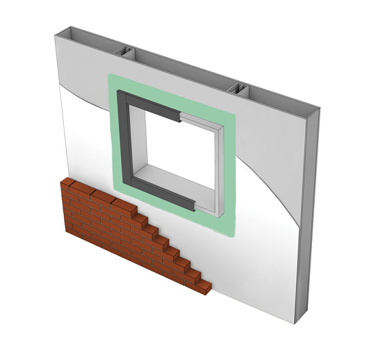
Image courtesy of Dow Corning Corporation
CONCLUSION
Controlling air leakage—whether from the outside in or from the inside out—is critical for building-enclosure performance and long-term durability. Selecting the correct air-barrier system for a given project is a decision that should be based on a number of factors, including permeability, component compatibility, performance and ease of application.
Ideally, one should specify a vapor-permeable, liquid-applied air-barrier system that:
- Provides primerless adhesion to common building substrates;
- Has a 100 percent water base for lower VOC content; and
- Is simple, functional, and backed by a trusted manufacturer.
COURSE CONTINUES AS A MULTIMEDIA PRESENTATION
Click on "Start the course now" at the top of the page to continue. There is no audio associated with this presentation.
ENDNOTES
11BSI-001: The Perfect Wall, Building Insights, Joseph Lstiburek, Building Science Corporation
2 ASHRAE – American Society of Heating, Refrigerating and Air-Conditioning Engineers
3 IECC – International Energy Conservation Code
4 WUFI® Pro 5.3, Fraunhofer Institute for Building Physics (IBP)
 |
Dow Building Science offers industry-leading technologies to enhance building design, durability, energy efficiency and occupant comfort. With DOWSIL™ Brand Silicones, we address a wide range of building and infrastructure challenges. |
Notice