Revolutionizing Ceiling and Wall Surfaces with Parametrics and Digital Fabrication


The Digital Design Process
Digital design partnerships often begin with a charrette between project architects and digital manufacturers. Josh Orona, LEED AP BD+C, associate at SRG Partnership Inc., described the use of a digital design process for the University of Oregon Sports Center. The architects were in project documentation before bringing their SketchUp and Revit models to the ceiling manufacturer for fabrication. The ceilings were treated as graphics and an opportunity to showcase flying ducks throughout the building. With a seven-month design schedule and a seven-month construction schedule, they needed to develop details that met fire safety codes for interior finishes as well as acoustic and lighting goals.
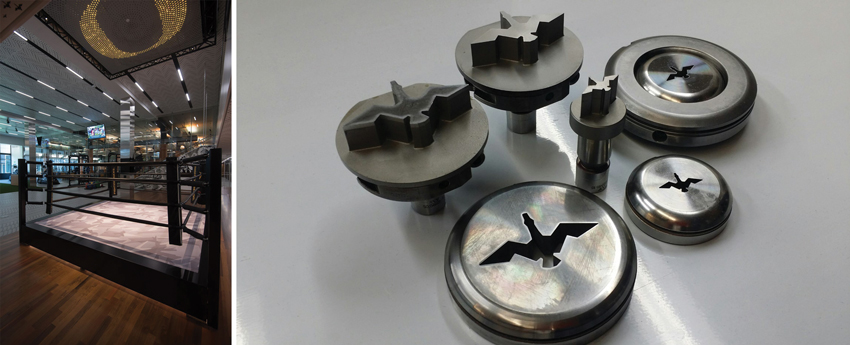
Customized cookie-cutter dies were manufactured as the shape of the holes in the acoustic ceiling throughout the Sports Center at the University of Oregon.
Orona was comfortable with a partnership with the manufacturer. “I had seen parametric modeling used on other projects at my previous firm,” he says. “It was used for facade studies and even programming studies. The first time I had experience with it was a project for the University of Oregon Executive MBA Program. We were trying to highlight the fact that the program was attracting people and partnerships from all over the world. We had designed a ceiling that had a perforation in the shape of a flattened globe—the perforations would provide lighting to the space. We had an idea that we could perforate the population centers so that the more populace the region, the more light would shine through. We used a digital design program to plug in population data to certain regions of the ceiling, and the program generated a pattern.”
Manufacturers who are able to fabricate materials based on parametric design information are able to input aesthetic and technical information into advanced software that communicates with fabrication machines. Predictive modeling of materials is based on aesthetics as well as environmental performance parameters. Using this methodology, architects can achieve conceptual integrity and technological control on more building surfaces. They are not limited to off-the-shelf solutions.
Design professionals are partnering not only with HVAC and lighting engineers but also with manufacturers who work with digital capabilities as they develop multiple options for the finished design. When information is inserted into advanced computer software, it instructs fabricating machines to construct the desired systems. It can also enable the construction of physical and digital models for design and client review. Branding the ceiling with the image of the University of Oregon’s duck mascot was an affordable “standard” rather than a custom process using new technology. Customized cookie-cutter dies were manufactured as the shape of the holes in the acoustic ceiling throughout the Sports Center. For the ceiling design for the University of Oregon, the digital model provided data on lighting levels, acoustic properties, airflow, material safety, and structural integrity while simultaneously retaining the design concept of a flock of ducks soaring overhead.
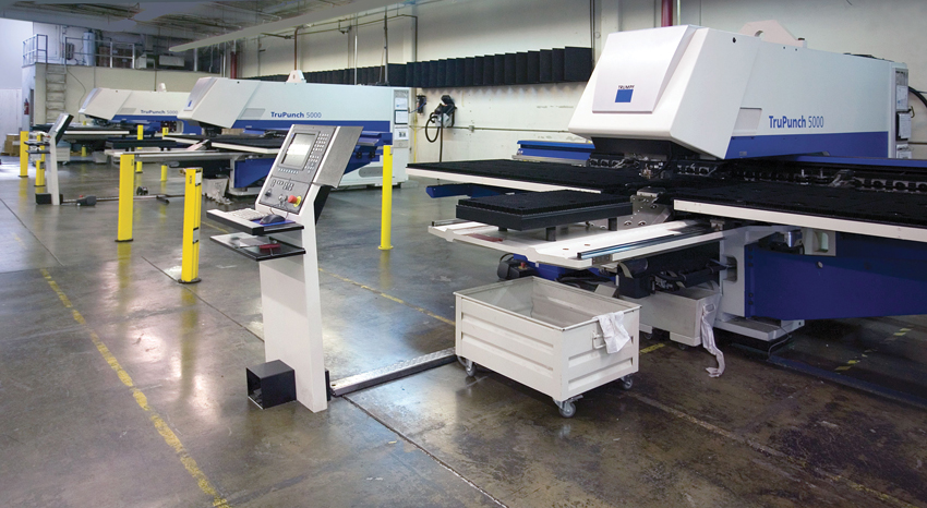
Fabricating punch machines are controlled by computers and can create multiple and custom designed sheets of ceiling materials without additional costs.
Environmental Controls: Lighting
When designing to enhance daylighting and reduce the use of electric lighting, architects are using new strategies that include enhanced digital design solutions. In the development of the new boarding lounges for the Airside Modification of the Hartsfield-Jackson Atlanta International Airport, Griffin knew that such a large project that included multiple solar and acoustic analyses needed a sophisticated solution.
The complexity of the intersection of design with the big data crunching involved with the calculation of lighting and acoustic levels soon led to parametric computer software and digital fabrication.
According to Project Architect Tyler Cline, LEED AP BD+C, associate at HKS, they moved quickly from hand sketches and small laser-cut models to digital images for the different areas of the airport concourses. This modernization project included several areas of the concourses and the AGTS train level.
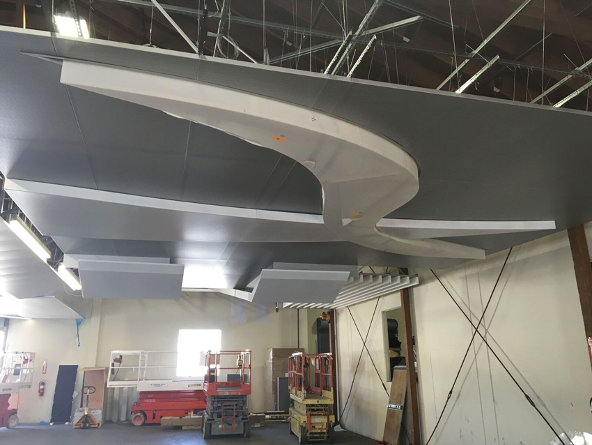
The lighting goal for the passenger holdrooms, where travelers gather before entering the passenger loading bridges, was to provide more natural light and use artificial light more efficiently. The designers wanted the ceilings in these holdrooms to suggest the images of airplane wings—designed to suggest movement and the sleek metals on airplane wings.
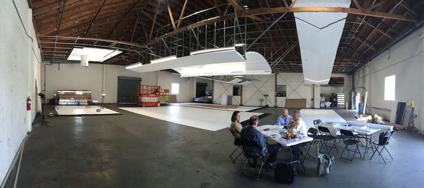
In order to achieve the desired high light reflectance values, a series of choices were used as inputs, then the digital fabricator produced mockups using standard and perforated tiles. They were able to evaluate the installation of a 14-foot glazing wall that would increase daylight in both the holding areas as well as throughout the concourse. The ceilings throughout the concourse were designed to guide passengers throughout the airport with integrated lighting as tool for wayfinding. More than 650,000 square feet of the ceilings were evaluated for lighting and acoustic parameters through digital and physical models to maintain conceptual integrity while developing a building that meets the highest safety and environmental standards.
The ceilings throughout the concourse were designed to guide passengers through the concourses with integrated lighting as tool for intuitive wayfinding.
The architects were not sure at the onset as to what type of file to bring to the fabricator. They had a .jpg of a dot matrix with a gray scale pattern that showed how they might want holes to be punched to achieve the abstraction of movement in the ceiling design. The architects then generated a unique digital pattern by using custom Grasshopper code. Grasshopper is a visual three-dimensional programming software integrated with another software program, Rhino. These are digital tools commonly used today by most architectural students and progressive architectural firms. They had a strong concept and needed assistance to achieve the reality of these one-of-a-kind mass customized ceilings. They met for a week with the manufacturer to explore their options.
Energy-saving benefits of several alternatives were modeled and tested. A white surface study can compare reflectance values for a variety of ceiling tile choices as well as locations. For this type of study, example spaces are identified, and for each space, both direct and indirect simple lighting schemes are studied. In each reflectance scenario, the floor may be assumed to be 20 percent diffusely reflective. The parameters for the properties in the materials for the ceiling and walls are varied. The materials are evaluated based on the amount of the preferred light reflectance values (LRVs) on the desired plane of maximum illumination. In addition, the ceilings must be efficient, structurally sound, and provide the preferred sound acoustic levels in the chosen location.
- Standard ceiling tile is considered to be the lowest reflective ceiling tile at 80 percent LRV.
- Acoustic ceiling tile is higher-end and is measured at 92 percent LRV.
- Micro-perforated tiles are modeled with and without perforations and may achieve a measured value up to 93 percent.
- The highest-end ceiling tile might achieve measured values up to 96 percent.
To evaluate the airport holding lounges, the programmers input room dimensions, ceiling height, floor reflectance, types of luminaires, wall tilt, and pitch. To measure daylight reflectance values, the operator inputs the luminaires, light loss values, mounting height, and the calculation plane at which the optimum illumination should be achieved. Light locations and perforations that describe a pattern can be evaluated as well as the cost of each type of ceiling. The designer can evaluate and choose a ceiling system that will maximize the available daylight and minimize the number of lights needed in the building spaces. Through digital modeling and fabrication, the design of the ceiling is customized and can be developed as a unique “kit of parts” fabricated for a specific function and unique building space.
The architect and the manufacturer were able to compare various lighting models to maximize comfortable lighting alternatives that are the most cost and energy efficient. The parametric models can optimize ceiling surfaces for daylight harvesting and glare reduction. They were able to model the geometry of glazing and shading to propose designs that mitigate glare while maximizing daylight for each particular airport terminal. While developing a ceiling with high LRVs, they also maximized the drama of the Great Hall ceiling.
While developing a ceiling with high LRVs, architects maximized the drama of the experience of traveling through the airport with integrated lighting as a tool for wayfinding.
Notice


