Design Flexibility Using Structural Steel
Architects address challenging urban site conditions through innovative structural design
![]() Continuing Education
Continuing Education
Use the following learning objectives to focus your study while reading this month’s Continuing Education article.
Learning Objectives - After reading this article, you will be able to:
- Identify and recognize the unique characteristics of structural steel systems that make them suitable for a variety of urban building sites.
- Investigate the design potential for alternative design approaches that allow for maximizing usable space within a restrictive urban site.
- Assess the functional contributions of structural steel systems in the creation of well-designed buildings.
- Design buildings that consider innovative construction approaches suitable to both new and renovated buildings.
When constructing new buildings, urban sites can present significant space challenges. The existing surroundings often impose limitations on the size of the site and its buildable area. Zoning requirements can restrict the building footprint and square footage plus dictate setbacks at different height levels. Pulling together the collaborative efforts of architects, structural engineers, fabricators, and installers, these challenges can be overcome in innovative and very effective ways. The teams of professionals that worked on four recent buildings in New York did just that by overcoming some real site limitations and meeting the building owner's goals in ways that achieved impressive results. We will explore in detail and review each of these four buildings.
510 Madison Avenue
Designing for Open Interiors
Project Credits
Location: 510 Madison Ave., New York, NY
Owner: Boston Properties, New York, NY
Developer: Macklowe Properties, New York, NY
Architect: Moed de Armas & Shannon, New York, NY
Architect of Record: SLCE Architects, New York, NY
Structural Engineer: Gilsanz Murray Steflcek, New York, NY
Mechanical Engineer: I.M. Robbins, New York, NY
Construction Manager: Tishman Construction Corp., New York, NY
Curtain Wall Consultant: Gilsanz Murray Steflcek, New York, NY
Structural Steel Erector: Falcon Steel, Co., Inc., Wilmington, DE
Curtain Wall Fabricator: Permasteelisa North America, Windsor, CT
Curtain Wall Erector: Tower Installation LLC, Windsor, CT
Metal Deck Erector: Falcon Steel Co., Inc., Wilmington, DE
A significant challenge that projects in urban environments face is meeting relevant zoning requirements. Through an innovative structural steel design, 510 Madison was able to maximize the floor area ratio within the constraints of its required setback to create a new, high-end high-rise tower on Madison Avenue in New York City.
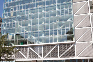
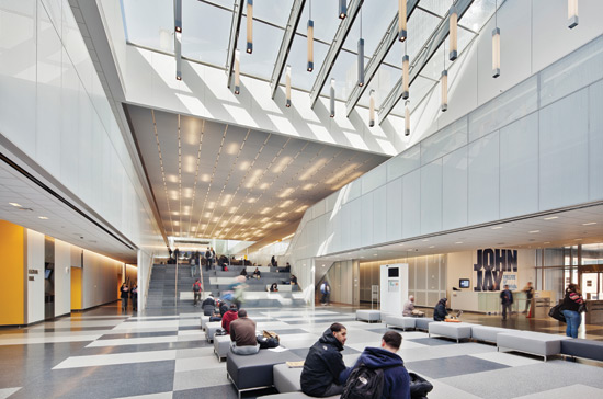 |
Steel framing is used to create open airy interiors such as this expansive connecting corridor at the John Jay Center for Criminal Justice. See John Jay Center case study on page 8. Photo by Eduard Huebersuch, courtesy of the Steel Institute of New York |
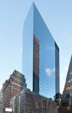 |
The tower and base solution of the building at 510 Madison Avenue in New York City. Photo by Moed de Armas & Shannon, courtesy of the Steel Institute of New York |
Design Problem—Work Within Zoning Setbacks
Completed in 2011 at the corner of Madison Avenue and East 53rd Street, 510 Madison certainly falls under the constraints of New York City zoning requirements that govern setbacks and floor area ratio. The usual response is to create a base and podium style structure with a profile that maximizes the amount of usable floor space. Originally planned as a residential tower, the recession shifted the priorities of owner and developer Macklowe Properties toward a 350,000-square-foot office building for the so-called Plaza District in Midtown Manhattan. Dan Shannon, the design architect in charge of the project for Moed de Armas & Shannon Architects, says the focus of the building was to create column-free tenancies of between 11,000 and 45,000 square feet. Zoning restrictions meant the street wall on the site perimeter could only go up to 85 feet before needing to step the building back for the tower above. “This created a structural challenge of driving the tower superstructure through the base without impinging on the quality of the base floor plate,” says Shannon. The owner had also purchased the air rights on the adjacent lot which would have allowed the building to go higher, but instead the team saw the value of protruding into the adjacent air space by approximately 8 feet to allow for larger floor plates.
Design Approach—Collaboration for an Innovative Structure
The design team of 510 Madison rose to the challenges of this situation and went beyond.
Through a carefully conceived structural design, they were able to minimize the space lost to interior columns and the stair core. The building was kept to only 30 stories (429 feet) in height meaning that the engineers at Gilsanz Murray Steficek (GMS) were able to use just two bands of large wide-flange outrigger trusses, one each at the bottom and top of the tower, to control drift. Most high-rise designs of this type include at least three such bands. This simpler system allowed the engineers to shrink the floor space needed for the braced structural frame within the tower section to the point of it being imperceptible, and added a full story of seemingly column-free office space. A 55-foot interior span ties the relatively small south-side core (only three elevators) to perimeter columns that are set back 1 foot, 10 inches from the aluminum glazed curtain wall. “There are 2 feet, 6 inches from the glass to the column line, so you really get this feeling of disconnection between the facade and columns,” says Karl Rubenacker, the GMS partner in charge.
In order to tie the tower to the base, an outrigger truss was used on the sixth floor to transition between the columns along the perimeter of the five-story base and the 25-story tower above, transferring the truss loads in the fifth floor ceiling with large 6-foot-wide by 9-inch-thick built-up plate girders. “The necessity of this truss gave the building a distinct architectural look of having the tower floating on the base,” says Shannon, the architect. “We couldn't just solve these problems with more steel, it had to be efficient and cost-effective.” The engineers addressed the imposed loads by adding more perimeter columns, which meant they could keep the scale of individual components smaller.
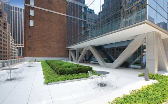 |
The story-tall transfer girders above the fifth floor help create a roof garden at 510 Madison Ave. Photo by Moed de Armas & Shannon, courtesy of the Steel Institute of New York |
The engineers used W18s for the interior spans, which allowed them to compress the ceiling plenum down to deliver those high ceilings within an overall 13-foot, 6-inch floor-to-floor height. Shannon also says that the design team focused on coordinating the mechanical system with the structure, designing penetrations in the beams to anticipate future ductwork. “Doing that after the fact is not that effective, but if you plan for this, it could happen efficiently,” he says. “Tenants understand how that affects ceiling height so they are happy to coordinate around the openings.” In the structural bays at the building corners, engineers removed the columns to provide an unencumbered corner office view that is a prized perk for high-end tenants.
The building envelope was designed to intensify the apparent lightness of the structure with floor-to-ceiling glazing that floods the interior with views and daylight, both of which are enhanced by 10-foot ceiling heights. Achim Hermes, a structural engineer and the building's facade consultant from GMS, says the goal for the exterior was a monolithic, uniform building. The unitized glass-and-aluminum curtain wall consists of nominal 5-foot-wide, one-story-high panels that are clipped onto anchors at the end of the floor plates. Tower floor slabs are 2-½ inches of concrete over a 3-inch, 18-gauge metal deck. The building slightly chamfers with a 2 percent slope through the top three floors, though the curtain wall was easily sloped without special requirements. The curtain wall panels have treated glass in the vision zone, which couples a low-emissivity coating with a relatively high 43 percent visible light transmittance. The glazed shadow box spandrel, which is hidden from the interior, barely reads from the exterior. “None of the facade units contain reinforcing steel; they were all within the limits to handle the wind loads,” says Hermes. The only departure from the curtain wall is the storefront system used along the ground-floor retail area.
Both the construction manager and the steel fabricator were brought on board during the design process, which helped to smooth over coordination and constructability issues in connections and steel quantities. Structural analysis was performed using a variety of software packages while the engineers at GMS used internal analysis spreadsheets to design all of the connections. A wind tunnel analysis had been performed for the original residential building, which was planned to be 700 feet tall, so the wind consultants performed a simpler desktop analysis based on that outcome. “The torsional velocity of the highest rented floor's corner office was used to set the controlling wind criteria for drift and stiffness” says engineer Rubenacker. GMS also carried out a progressive collapse study, which resulted in no changes to the design. The steel structure ties directly into concrete footings below grade on Manhattan's rock, with the sub-grade level enclosed by a concrete foundation wall with an at-grade concrete slab.
Result—High Design Through Good Engineering
The finished building, now owned by Boston Properties, was recently certified LEED Gold for Core and Shell, which in part relied on recycled steel used in the structure. An exposed structural steel stair also leads down to a basement health club complete with a swimming pool, another perk geared toward the expectations of high-end tenants. Added in with the high ceilings, column-free tenancies, and elegant outrigger truss transfer, 510 Madison has proven successful in attracting tenants, even in a challenging market.
Columbia University Northwest Corner Building
Building Around Existing Structures
Project Credits
Location: Broadway and West 120th Street, New York, NY
Owner: Columbia University, New York, NY
Design Architect: Rafael Moneo Valles Arquitecto,
Moneo Brock Studio, Madrid, Spain
Architect of Record: Davis Brody Bond Aedas, New York, NY
Structural Engineer: Ove Arup & Partners Consulting Engineers,
PC, New York, NY
Mechanical Engineer: Ove Arup & Partners Consulting Engineers,
PC, New York, NY
Construction Manager: Turner Construction Company, New York, NY
Curtain Wall Consultant: R.A. Heintges & Associates, New York, NY
Structural Steel Erector: DCM Erectors, Inc., New York, NY
Miscellaneous Iron Fabricator and Erector: Post Road Iron Works, Inc.,
Greenwich, CT
Ornamental Metal Fabricator and Erector: Empire City Iron Works,
Long Island City, NY
Curtain Wall Fabricator: Sota Glazing Inc., Brampton, ON
Curtain Wall Erector: W&W Glass, LLC, Nanuet, NY
Metal Deck Erector: Solera / DCM, New York, NY
Another project forcing collaborators to get creative because of existing site conditions, Columbia's Northwest Corner Building used an engineered steel frame to span over an existing gym. This structure was designed to eliminate vibrations in interior lab spaces and provide long-span spaces for a cafe, library, and labs.
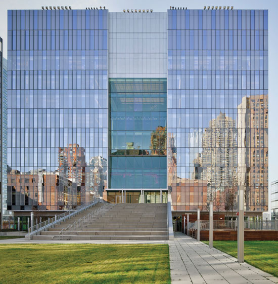
 |
The Northwest Corner Building at Columbia University in New York City needed to span over an existing gymnasium to create the needed space in the upper floors. Photo by Arup, courtesy of the Steel Institute of New York |
Design Problem—Build Around an Existing, Operating Gymnasium
Columbia University, like most universities, uses peer schools as a way to benchmark their own performance and facilities. Back in 2002, the administration determined that the university was in danger of falling behind in one key area—it had no cutting-edge, 21st-century laboratory facility that could match what peer schools like Harvard or Princeton were erecting.
To close the gap, Columbia hired the well-known Spanish architect José Rafael Moneo to design a contemporary laboratory building on the last remaining major undeveloped plot of the original McKim, Mead & White-designed campus—the northwest corner. The site, however, came at a price. Whatever was to be built there would have to share its footprint with the existing Dodge Physical Fitness Center—notably its basketball facility, home to Columbia's Division One Lions.
“The basic challenge was to come up with a structure that would span 120 feet over the existing gym, and to facilitate construction while the gym was closed,” explains Dan Brodkin of Arup, whose firm collaborated with Moneo on the design. “We experimented with many possibilities, and decided to create a building like a bridge.” While this addressed the structural issue, the occupancy issue was complicated since the New York City Department of Buildings requires that two floors be completed before a space below can be occupied. Columbia wanted the gym to be open in time for the Lions to begin daily practices so construction had to move at a rapid pace. With long spans and a narrow timeline, the choice of structural material came easily: The building would be framed out of structural steel to cover the long span and keep the building light in weight.
Design Solution—Bridge Over the Existing Space with Long-Span Steel Structure
At 14 stories and 188,000 gross square feet, the Northwest Corner Building, as it is now known, packs a lot onto its 65-foot-wide site. To keep all of this space stable and immune to live loading—lab buildings are adverse to vibration and sway—Arup decided to use the whole height of the building as the truss. In other words, the engineers allowed for filling each of the perimeter framing bays with diagonal bracing elements, and put one giant chevron—a big V—through the center of the elevation. “There's a pay-off to this approach,” continues Brodkin. “There are more bits and pieces, but it's deeper and stronger.”
 |
To accomplish the building’s engineering feat, the entire building was designed as a truss with the structure incorporated as an exposed design element. Photo by Adam Friedberg, courtesy of the Steel Institute of New York |
The internal system runs longitudinally -south through the building, sandwiched between the corridor and offices of the east side and the laboratories of the west side. Framed with mid-range W14 wide flange sections fabricated from Grade 50 A992 steel, the big V cuts the span of the truss in half, while its easily understood, rational load pattern makes it simpler to thread mechanical systems through the building.
The expected loads actually did not call for bracing elements in every perimeter bay, so the engineers had the freedom to decide which would be braced and which wouldn't. Arup came up with a computerized force weighted random structure generator that began by assuming mathematically that every space between column and beams would have an X brace. This model was then analyzed and the engineers deleted every bracing element in compression while maintaining every element in tension. Then they analyzed it again, grouping the diagonal members based on their force level—600 to 900 kips were grouped as high force, 300 to 600 kips as medium force, and 50 to 300 kips as low force.
With these groupings in place, the team set up an algorithm that they applied to each group, allowing the computer to randomly delete 70 percent of low-force members, 40 percent of -force members, and 10 percent of high-force members. Arup then began to play with its numbers, sometimes deleting hard-working members, sometimes lighter-working members. Each time, a different load pattern emerged. When hardworking members were deleted, the pattern became weird and unexpected, but when lighter-working members were deleted the pattern was more rational.
This process became an integral part of the final look of the exterior and Moneo was a willing collaborator. He gravitated more toward the rational expressions generated by deleting the low-force members, and Arup ran the program playing with the numbers until they found one that he determined was consistent with the overall design intent. In the final assembly, the bays and diagonals are framed with a variety of mid-range W14 wide flange sections fabricated from Grade 50 structural steel.
Construction—Innovation in Process
While mathematically this building-as-truss system functioned fine as a means to carry the structure over the 120-foot span of the gymnasium without bearing on it, the design assumed that the entire assembly appeared magically in place and did not take into account the step-by-step, bottom-up nature of the construction process. To manage this essential procedure, a system would have to be developed to shoulder the building's massive dead loads while it was being built.
In answer, Arup devised a system of three, full-floor-height jumbo trusses that would span across the gym and serve as a launch pad for the rest of the structure. It would handle dead loads during construction, and help to manage live loads once the erection was complete. These trusses, approximately 400 to 500 tons each, were constructed from massive W14x730 wide flange sections reinforced with 4-inch-thick steel plates welded across the webs. The trusses tie into eight similarly hefty columns—W14x730 wide flange sections reinforced with 4-inch-thick steel plates—five on the north side of the building, three on the south, that transfer the gravity load down to bedrock.
However, these jumbo trusses were too large to fabricate off site and then truck in. They were also too heavy to lift into place with a crane, or to assemble while bearing on the roof of the gym. Working out a plan with erector DCM, Turner Construction assembled the components on a heavy construction shed above the sidewalk on Broadway, connecting them with complete joint penetration welds. Because the location of the tower crane would have interfered with the area needed for this work, its base was bumped out from the building to provide room for assembly of the trusses. Once assembled, they set up temporary steel beams spanning the roof of the gym, greased them liberally with lubricant, and slid the trusses into place with hydraulic rams.
The remainder of the steel structure is relatively straightforward, excepting the laboratory bays with their 40-foot clear spans and 18-foot floor-to-floor heights. Moneo and executive architect Davis Brody Bond Aedas set up these wide-open spaces to create greater flexibility within the facility, allowing for different scientific disciplines to augment any floor to its needs—a move that will keep the building relevant well into the future. Castellated beams frame these bays, allowing mechanical systems to be run through the web openings. The double-height floors allowed mezzanine levels to be set up on the east side of the building, a literal beehive of faculty offices and student breakout space.
Without structural steel—some 4,000 tons of which were used in the project—few if any of these innovative design decisions would have been possible.
The Barclays Center
Sports Geometry
Project Credits
Location: 620 Atlantic Avenue, Brooklyn, NY
Owner/Developer: Forest City Ratner Companies, Brooklyn, NY
Lead Architect: AECOM, New York, NY
Design Architect: SHoP Architects, New York, NY
Structural Engineer: Thornton Tomasetti, New York, NY
Mechanical Engineer: WSP Flack & Kurtz, New York, NY
Construction Manager: Hunt Construction, Brooklyn, NY
Curtain Wall Consultant: Front Inc., New York, NY
Structural Steel Erector: James F. Stearns Co., Inc., Pembroke, MA
Miscellaneous Iron Erector: Berlin Steel, Kensington, CT
Architectural and Ornamental
Metal Erector: Harriott Contracting, Columbia, MD
Curtain Wall Erector: Egan Architectural, Yonkers, NY
Brooklyn's new multipurpose indoor arena relies on a structural steel geometry that provides unobstructed views to keep visitors coming back often. The use of structural steel allowed the Barclays design team to make several grand gestures, including a bowl-shaped arena with steep seating slopes to create a unique viewing experience for sports fans and concertgoers.
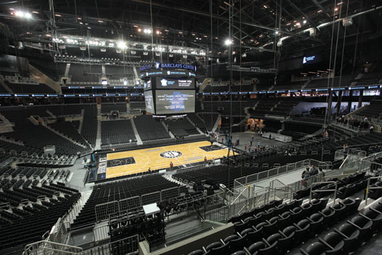 |
The wide open space of the Barclays Center was achieved through structural steel design. Photo by Bruce Damonte, courtesy of the Steel Institute of New York |
Design Problem—Create a Positive Viewing Experience for Sports Fans and Concertgoers on a Tight Urban Site
When ticketholders arrived for the series of Jay-Z concerts that officially opened Brooklyn's new Barclays Center on September 28, 2012, they were treated to a dramatic view of the lighting cluster above the stage from the moment they walked onto the center's main entrance plaza. The design team intentionally planned this experience so visitors could visually connect with the massive arena's interior while still outside at the corner of Atlantic and Flatbush Avenues. Not only would this help them find their way into the building, but glimpses of the three-story, 70,000-pound central scoreboard would pump up fans on game days.
This seemingly simple gesture, which creates a quintessential only-in-New York street scene, relies in large part on several structural engineering maneuvers that nestled the 675,000-square-foot arena into its site on the northwest corner of the 22-acre Atlantic Yards development. As a result, unlike several new arenas developed in the last decades in other American cities, the scale of the Barclays Center does not appear to overwhelm its site. This was a critical gesture for Forest City Ratner Companies (FCRC), the Barclays Center's developer that had famously struggled to win community support for the overall development.
Design Approach—Structural Steel Creating a Steep Bowl Shape Spanned by Truss System
The seating bowl of the arena, which rises from approximately 30 feet below street grade and makes these visual connections possible, has similar sightlines to those of Indianapolis's Bankers Life Fieldhouse. That project, which relied on a concrete superstructure and steel roof trusses, was designed by Ellerbe Becket Architects and Engineers (now AECOM), who adapted the configuration for Barclays' superstructure while SHoP Architects designed the exterior, as well as some interior architecture components.
“Everything in the design of an arena evolves from the bowl design,” says Steve Duethman, AECOM's project manager for the Barclays: Ticket price points, luxury suites, and other requirements of the 19,000-seat arena all rely on the geometry set by the bowl.
Structural engineers at New York's Thornton Tomasetti (TT) developed a modified version of the Indianapolis arena's structure for Brooklyn's project. Jeff Callow, TT's project manager for Barclays', says although the Indianapolis project provided a timesaving template, the congested site at Barclays, as well as market considerations, led the team to adopt a steel structure. This eliminated the potential scheduling challenges of having too many trades on the site at once. The primary differences between the Brooklyn structure and Indianapolis are the use of a tied-arch roof truss system, rather than a more conventional arched truss, a steel superstructure rather than concrete, and precast concrete stadia units spanning between steel rakers, as opposed to cast-in-place units.
Callow says the tied-arch system was used as an efficient means to achieve the 350-foot-long span of the roof. The Indianapolis arena resolved arch thrust forces using the lateral stiffness of the concrete superstructure. Due to the relatively tight urban site of Barclays, the design-build team determined it was preferable to construct the entire superstructure from steel to limit activity to one construction trade on site during the erection sequence. However, Callow says that, given the limited real estate on which to build, steel structure would not inherently have sufficient lateral stiffness to resist the arch thrust forces alone. By introducing the tension tie to balance the arch forces, the thrust forces imposed on the superstructure are greatly minimized. Two main tied-arch trusses run in the long east-west direction, spanning approximately 350 feet. Each comprises a 12-foot-6-inch-deep arched upper truss, with chords made up of W14s that vary across the section and a tension tie, consisting of a 14x311 wide-flange member, which occurs approximately 50 feet below the top of the arched truss and 10 feet above the lower ends of the truss owing to the demands of sight-line preservation.
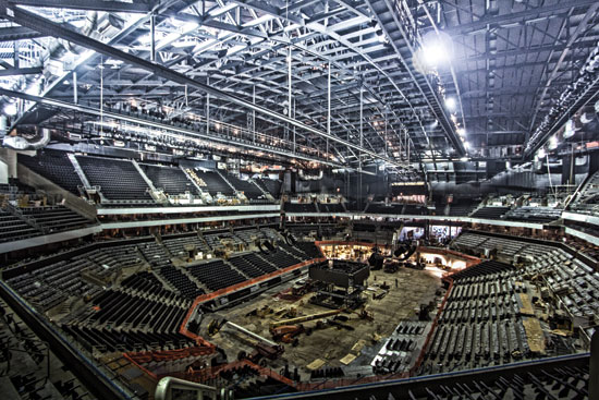 |
Barclays Center during construction showing the concrete base and the steel components above Photo by Bess Adler/Thornton Tomasetti, courtesy of the Steel Institute of New York |
Construction—Unique Steel Design and Erection Process
The truss configuration was largely dictated by the limitations of shipping the trusses from the fabricator. The tie is hung by a series of eight, 8-inch vertical HSF pipes. Sixteen smaller trusses connect with the large longitudinal trusses and provide the free span of the arena with chord sizes varying from 14x90 to 14x159. Dead loads and lateral loads are resolved into the steel superstructure, with thrust forces from the trusses largely balanced by the ties. Callow says one of the project's main structural challenges was connecting the tied arch to the steel superstructure that rings the Barclays and forms its street-side concourse. In a conventional design, where the tension tie would connect at the ends of the truss, the truss would rest on a roller or bearing support that could allow the truss some movement. However, in the case of Barclays, the connection had to be able to transmit some lateral forces to the superstructure.
While the introduction of the tension tie significantly reduces the amount of thrust imposed on the superstructure, it does not eliminate it completely due to strain compatibility between the tension tie elongation and the superstructure lateral displacement. To minimize this effect, TT specified a construction sequence involving leave-outs of elements to disengage the arch thrust resistance of the superstructure for de-shoring of the roof structure. This forced the tied-arch action to resist the initial dead load. After the roof was de-shored, these leave-out connections were completed, leaving the superstructure to resist thrust forces under future environmental and live load conditions. Live loads are chiefly snow, which is prevented from sliding onto the sidewalk by a series of 16-by-16-inch tube steel members, approximately 1 inch off the roofing membrane, that form fences to spread the snow across the otherwise conventional built-up roof.
A total of over 10,500 tons of ASTM A992 Grade 50 structural steel is used in the project, in addition to the 600 tons of steel used for the weathered steel panels on the facade. Aside from the usual ice rink floor to support hockey games and entertainment events on top of a fairly conventional 6-inch slab on grade, the arena's interior includes an exceptional internalized loading dock on the basement level (approximately 30 feet below grade) that relies on elevators and a massive 180-degree turntable to get trucks in and out of the arena. The relatively cramped site meant a conventional street-level ramp to a loading dock could not be accommodated. Two truck elevators, with a capacity of 80,000 pounds each, serve in the same capacity as ramps, freeing up ground-level space for street-facing retail and large expanses of glass that make the Barclays feel more a part of Brooklyn's bustling downtown. And although the center abuts nearby tunnels for New York's subway system, no special structural accommodations had to be made outside of construction-stage shoring.
An 85-foot cantilevered canopy over the main entrance represented a last-minute challenge to the structural design. To support the added loads, Thornton Tomasetti designed two 12-foot-6-inch-deep primary trusses on each side and then laced them together with diagonals to create boxed trusses that tie back to the superstructure columns at the edge of the arena bowl. In spite of the complicated design, Callow estimates only 10 or so structural RFIs for the project. This was due, in part, to working directly for Hunt Construction, but also to TT's use of sophisticated modeling and design software, particularly Tekla for 3D modeling and connection details, SAP2000 for analysis, and RAM Structural System for floor framing.
An integrated design and construction team approach saved much time by short-circuiting questions regarding connections and structural cambers that could reduce overall steel tonnage. The project is currently pursuing LEED Silver certification for new construction, but the success of recent concerts and the inaugural Brooklyn Nets basketball season has quickly made the Barclays seem as if it were always there, ready for New York to walk inside.
John Jay College of Criminal Justice
Renovating for Modern Needs
Project Credits
Location: 524 West 59th Street, New York, NY
Owners: The City University of New York John Jay College
of Criminal Justice, New York, NY; Dormitory Authority
of the State of New York, New York, NY
Architect: Skidmore, Owings & Merrill LLP, New York, NY
Structural Engineer: Leslie E. Robertson Associates, New York, NY
Construction Manager: Turner Construction, New York, NY
Structural Steel Erector: Cornell & Company Inc., Westville, NJ
Miscellaneous Iron Fabricator and Erector: United Iron, Inc.,
Mt. Vernon, NY
Curtain Wall Fabricator and Erector: Enclos Corp., New York, NY
Metal Deck Erector: Cornell & Company Inc., Westville, NJ
Projects in urban environments often have the added challenge of working around existing site conditions, including city infrastructure. Such was the case for John Jay's new school, which used structural steel to cantilever its 15-story tower over an Amtrak tunnel.
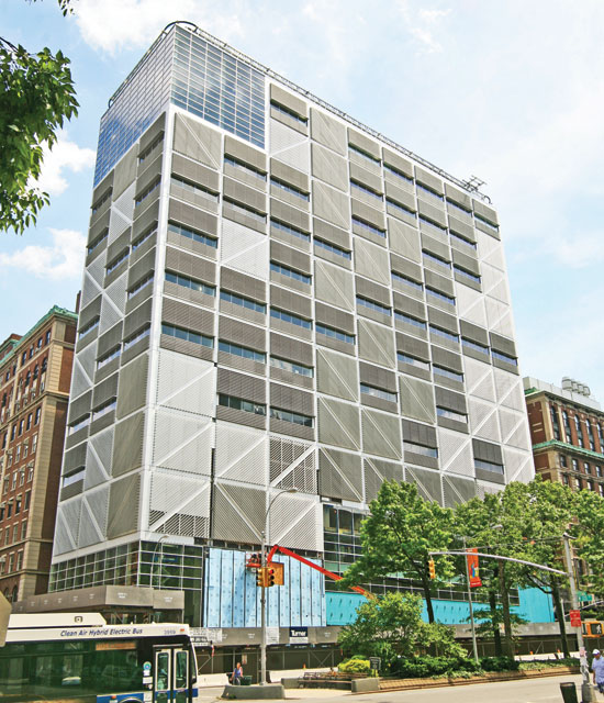
 |
The steel-framed John Jay Center for Criminal Justice in New York City. Photo by Eduard Hueber, courtesy of the Steel Institute of New York |
Design Problem—Achieve Educational Program in a Tight Urban Site
The tower design, envisioned by architecture firm SOM as a vertical campus—essentially a stacked academic program that seeks to offer the same opportunities of random encounter and collaboration common to more traditional campuses—itself added more challenges. The design called for double-height spaces and 50-foot clear spans through the center of the building.
In the words of Jason Stone, associate at structural engineering firm Leslie E. Robertson Associates (LERA), “Steel was the obvious choice because it's lighter than reinforced concrete and keeps the loads down. It was also the only option for the project's long span areas.” The tower and a 500-foot-long podium that connects the addition to John Jay's existing facilities on 10th Avenue make up a 620,000-square-foot expansion at the college.
SOM took advantage of this long, low podium space, as well as the nearly two-story grade change between 10th and 11th Avenues, to solve one of the problems of urban campus design. “One of the greatest challenges in city colleges is how to move a multitude of students who have to go from class to class in 10 minutes over vast floors,” says Mustafa Abadan, the SOM partner in charge of the project.
In the podium, the architects arranged classroom functions around a cascading circulation corridor that descends from the top of the podium down three flights to the first floor of the college's foundation building, the former De Witt Clinton High School, constructed in 1906. “The corridor creates sectional cutouts across three floor plates,” continues Abadan. “It looks like Broadway cutting through the Manhattan grid and creating public squares.” A green roof tops the podium, creating an idyllic oasis for students in the midst of a concrete jungle.
SOM divided the tower into three academic quads—one for the sciences, one for humanities, and one for economics and rational thinking—each with its own double-height space. These double-height spaces run unobstructed through the center of the building from 11th Avenue to the podium. The nature of the enclosure helps to open up the spaces even more. “The building has a predominantly glass exterior with frit patterns and lets lots of natural light into what are traditionally closed-up classrooms,” says Abadan. “It also helps address the notion of the transparency of justice. The college is teaching people to be enforcers of justice and wants to instill in them that whatever they do in the field has to be transparent to society.”
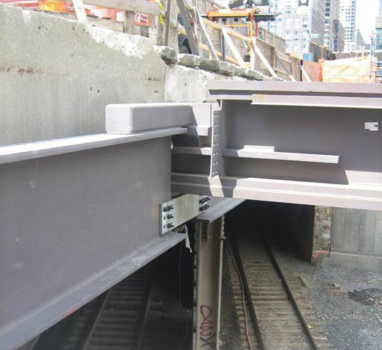 |
Steel box girders and precast concrete panels support the building above an Amtrak tunnel at the John Jay Center for Criminal Justice. Photo courtesy of the Steel Institute of New York |
Design Approach—Cantilever the Building Over an Amtrak Tunnel
The site's chief limitation—the Amtrak tunnel—called for an innovative structural design, and LERA responded with a scheme that takes full advantage of structural steel's lightness, ductility, and strength. Cantilevering the corner of a 15-story high-rise over an Amtrak train tunnel, which offers no possibility of bringing a direct load path to bedrock, isn't a job for just any structural material. In this sort of condition, the engineers knew that structural steel was the only material with the strength-to-weight ratio capable of handling the dynamic forces at play.
The building's anticipated dead loads promised to be too great to cantilever the entire building over the tunnel. Instead, the engineers devised a plan in which the first five floors cantilever out from the foundation on two jumbo box girders, while the upper 10 floors hang from a truss system that connects to the braced-frame core.
“This arrangement had a couple of effects,” says Stone. “It reduces the load over the Amtrak tunnel—five floors of load instead of 15. It also created a dramatic architectural feature. The fifth floor has no perimeter columns. Below you have normal columns that go down to grade, and above you have hangers that come down from the roof, but at the fifth floor there's nothing at the perimeter at all. This worked out for the school as that floor is home to a large cafeteria.”
One of the box girders that support the first five floors above the Amtrak tunnel weighs almost a ton per foot of length, with a total weight of close to 50 tons. Its top and bottom flanges are 4 inches thick by 5 feet wide. Its web plates are 1½ inches thick and the total depth of box is 3 feet, 2 inches. The other girder is a built up I-shape with 6-inch-thick flanges fabricated by welding a 3-inch-by-24-inch inner plate to a 3-inch-by-28-inch outer plate and a 2-inch web plate. The depth of both members is only 3 feet, 2 inches each, because this was the maximum dimension that would fit between the sidewalk and the Amtrak tunnel below. Vibration pads were used to isolate the building from the movement created by passing trains.
Construction Process—Use Structural Steel to the Advantage of Sequencing
To erect the unusual structure, local ironworkers installed temporary perimeter columns at the fifth floor in order to complete topping out the structure. The hangers—designed to be in tension in their final state—had to handle compression forces during construction, so temporary angles were bolted onto them to stiffen them.
The hangers were fabricated from plates ranging in size from ¾ inches thick by 8 inches wide up to 2 inches thick by 20 inches wide. (Spaced 30 feet apart, the hangers are concealed within partition walls without the usual bump-out, creating unimpeded views.) The floors were built to a height 3 to 5 inches above their final intended elevation so that, when the temporary columns were removed and the trusses began to deflect under the load, the floors would end up level.
“We had to do a detailed analysis to accurately figure out how far different points of the floors were going to come down,” says Stone. “It worked as predicted. In the end we were within a very small tolerance.” The building has two C-shaped cores that flank the 50-foot clear span areas of the tower. They are built up from wide flange sections that range from W14x109 to W14x665 and from HSS 6x6x3/8 up to HSS 8x8x3/8 sections used for vertical bracing. The trusses' top and bottom chords are built up of plates that range from 3x15 up to 4x28 welded to W18 floor beams. The truss diagonals range from W14x43 up to W14x550. The horizontal podium's structure is of typical moment frame construction with a few exceptions. The columns are W8, 10, 12, and 14, but mostly W14s. The sizes of the W14s range from W14x68 to W14x159. The beams are W12 to W40 with the most common shapes being the most efficient ones—W12x22, W14x22, W16x26, W18x35, W21x44, W24x55, and W36x135. For the longer span girders and the cantilever conditions created by the open central circulation space the engineers went up to W40x583. Most of the heaviest members are at the fifth floor supporting the green roof and over the 59th Street entrance, which is recessed with structure spanning above.
All of the structural steel used in the project, a total of 7,650 tons, is A572 Grade 50. LERA worked hard to limit on-site welding to speed up construction so all of the built-up elements were shop welded, delivered to the site whole, and bolted into place with ¾, -inch and 7/8-inch A325 bolts and 1-inch and 1-1/8-inch A490 bolts. LERA and SOM partnered closely with Owen Steel, the structural steel fabricator, and the steel erector, Cornell & Company. “There's a great relationship between all of us,” says Stone. “Very much at the end we agreed it was a special job that required extra coordination and collaboration. They were on board right away and they were really great.”
The Steel Institute of New York is a not-for-profit association created to advance the interests of the steel construction industry. The Institute sponsors programs to help architects, engineers, developers, and construction managers in the New York building community develop engineering solutions using structural steel construction. www.siny.org |