Thermal and Moisture Control in Exterior Metal Walls
Achieving durable, economical, and sustainable metal wall systems
![]() Continuing Education
Continuing Education
Use the following learning objectives to focus your study while reading this month’s Continuing Education article.
Learning Objectives - After reading this article, you will be able to:
- Describe thermal and moisture control performance for exterior metal walls.
- Define the components of an exterior wall system assembly.
- Analyze how different climates affect design of exterior wall systems.
- Review the advantages of using rainscreens in building design.
- Evaluate design criteria for superior performance exterior wall systems.
Water in liquid and vapor states, and temperature changes have long been recognized as the most destructive weathering elements affecting the entire building envelope, especially exterior walls. Accordingly, moisture management and thermal efficiency are critical keys to a successful exterior wall system. This success is best achieved when buildings are designed to respond to environmental and climatic conditions. However, since the predominant design of exterior walls currently employs multiple material components that are used in different climates, care must be taken to understand the interaction and proper selection of those different components.
1. Moisture Problems and Causes
The rapid rise of energy costs in the early 1970s led to a new standard of design for building envelopes that was more energy efficient and airtight than before. This is reflected in the growing number of energy code changes that require higher R-values and lower air infiltration rates for exterior walls, and other parts of the building envelope. Meanwhile, occupied spaces of buildings achieve relative humidity (RH) levels that are frequently around 40 percent. The combination of these energy efficiency changes and this comparatively higher moisture level has caused a new concern regarding moisture retention in exterior wall systems that can create design challenges for architects. The problems caused by the presence of moisture in a wall system cavity include:
- Corrosion of metal structural elements in the wall cavity.
- Reduction of thermal values of some insulation.
- Deterioration of internal components, such as tapes and wraps.
- The potential for the growth of mold within the wall system.
|
While the first three of these concerns are common and long standing, mold has emerged as a major concern, particularly in multi-component walls. The three elements required for mold to grow are water (in vapor or liquid form), moderate temperature, and an organic food source that applies to many wood-based or paper-covered building materials. Moderate temperature inside a wall cavity is common, which means that controlling mold requires eliminating either the food source or moisture, or both.
2. Performance Requirements for Outer Wall Materials
The weathering element of a multi-component wall system is the outer wall material. In addition to being the aesthetic wrap for the building, it is very important in determining the rest of the wall system design. Moisture management begins with the selection of this outer material.
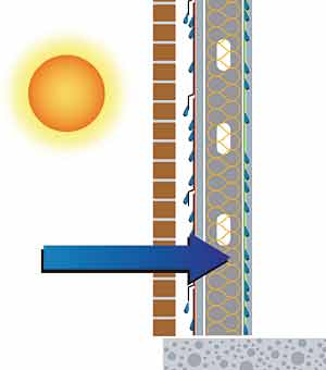
Porous Materials
Materials like masonry, precast concrete, Exterior Insulation
Finish Systems (EIFS),and Glass Fiber Reinforced Concrete
(GFRC) are porous materials that will absorb and retain moisture.
Wind-driven rain in particular can be an issue for these porous
building materials that challenge designers to address the
conditions that arise after a storm. When the sun heats up
the outer wall, the absorbed moisture is changed to water
vapor. The vapors move from the warm, high-RH area to the
colder, often air-conditioned interior. A problem can occur
in cold or moderate climates where the vapors can pass through
the wall system components, enter the wall cavity, and condense.
|
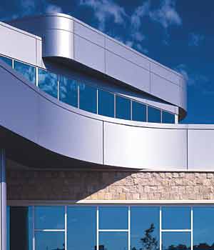
Non-Porous Materials
Other materials, like metal, glass, and polymer-based walls
are non-porous and do not retain moisture. They eliminate
a large portion of the moisture or water vapor problem through
their characteristic of not absorbing water. Metal cladding
systems are such materials and they can further be designed
to act as rainscreens, to minimize water entry and to ventilate
wall cavities where moisture can collect.
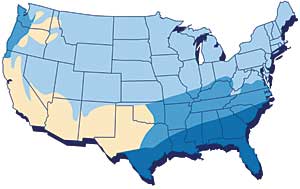
3. Climatic Zone Considerations
Each of the four U.S. climatic zones raise varying degrees of moisture concerns. (Figure 2) In the southeast, during the summer months, the hot and humid ambient conditions can lead to entrapment problems in the wall system. For the northern states, moisture control is more moderate during the summer, while controlling moisture from interior conditions during the winter is critical. Arid areas are considered low risk and do not have moisture problems.
|
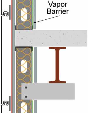
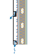
Moisture Control Designs for Cold
to Very Cold Climates
Key elements for controlling moisture in a typical multi-component
wall assembly for cold climates (Figure 3) are:
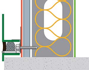
- The vapor barrier−retarder: Airflow and vapor move from warm high pressure to cold lower pressures. In northern regions, winter is the critical time, when outside temperatures will average 8 degrees Fahrenheit, with a 20 percent RH and the interior ambient is 70 degrees Fahrenheit, with a 40 percent RH. Given these conditions, the dew point of the wall is 45 degrees Fahrenheit. If the vapor barrier-retarder were ineffective, vapors that enter the wall cavity would condense at a rate of as high as three pints of water per 100 square feet of wall area per week.
|
- Air and water barriers: An ineffective air barrier causing
air leakage is considerably worse, because 80 pints of water
could condense in the same one-week time frame. The comparison
depicts how critical the air barrier is for moisture control.
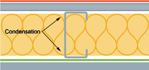
Using the previous temperatures, consider the temperatures of the metal studs (Figure 4). These range from 17.5 degrees Fahrenheit on the exterior side to 37 degrees Fahrenheit on theinterior. This is significant, indicating a problem with either the air or vapor barriers entering the cavity. Any surface that is below the dew point of 45 degrees Fahrenheit and in contact with the moisture laden air will cause condensation. Condensation in the cavity will cause corrosion of the stud and reduction in the thermal value of fiberglass insulation (Figure 4).
|
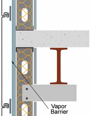
Moisture Control Designs for Hot and
Humid Climates
In hot, humid southern climates, where moisture is a concern
during the summer, the vapor barrier is installed at the exterior
of the wall system (Figure 5). This layer is frequently a
multipurpose material providing an air, water, and vapor barrier.
Any breaks in this barrier will allow air and vapors to enter
the cavity. The temperature of the metal studs can be below
the dew point when adjacent to interior gypsum, and condensation
will form, causing corrosion, along with insulation and gypsum
board deterioration problems.
|
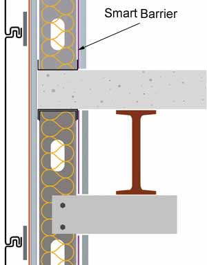
Moisture Control Designs for Moderate
Zones
In moderate climate zones throughout the U.S., a "smart"
vapor barrier is often installed in the wall system (Figure
6). It is typically located on the interior of the studs and
has characteristics that allow variable amounts of air and
water permeability. When installed correctly, the perm rating
actually changes with the change of relative humidity. During
the winter when RH is low, the perm rating is 1, and during
the summer with high RH the perm rating changes to 10 (Figure
6, Centria #9).
|
4. Multi Component Wall Systems
Multi-component wall systems are made up of numerous individual components that require careful design attention in order to avoid some common challenges related to thermal, moisture, and structural concerns. Typical components and concerns include:
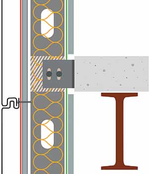
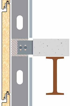
Metal Studs
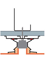
A major structural concern with the use of metal studs on
a concrete floor slab is the deflection in the floor that
can be transferred to the exterior wall system. This design
can cause the deflection stresses to pass through the studs
to the single most expensive element of the wall, the outer
wall material. The solution is to move the studs outboard
of the floor slab and use slotted connectors to handle the
deflection (Figure 7). Not only is this is a better design,
it is also a less expensive solution.
|
Insulation
The second component is the thermal barrier, or insulation.
Frequently fiberglass insulation is used in the cavity between
the metal studs. While fiberglass has been tested to provide
reliable thermal protection at a reasonable cost, there are
concerns with its effectiveness when it is used in combination
with metal studs, however. This has been documented in ASHRAE
90.1, which is the basis for many energy codes used in the
U.S. (As of 2005, only 7 states do not reference this standard,
while the other 43 states represent over 75 percent of the
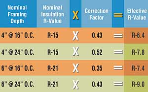
commercial construction in the U.S.) ASHRAE 90.1 requires
reductions in the calculated value of the insulation by using
"correction factors" (Figure 8). Note that a six-inch
stud, filled with fiberglass insulation, at 16-inch centers
has a theoretical R-value of R-21 but is severely reduced
to only a value of R-7.4. The reason for the reduction is
based on the thermal conductivity of the metal studs and the
net effect on the overall heat transfer of the wall system.
|
Vapor Barrier−Retarders
This component of the wall system is climate dependent with
stud cavity insulation. In cold climates, it is located on
the interior of the metal studs. A key to good performance
of a vapor barrier-retarder is continuity of the material,
so as to avoid gaps or breaches. Challenges in maintaining
this continuity occur at floor slabs, behind spandrel beams,
at electrical box penetrations, and at the roof and wall intersection
at parapets (Figure 9) . The condition at the parapet is critical
because it relies on coordinating wall and roofing contractors
to maintain vapor barrier continuity. Electrical distribution
is a challenge because frequently it is done in the stud cavity.
Hence, at every electrical box, the vapor barrier is penetrated,
causing a breach in the vapor barrier continuity.
Exterior Gypsum Sheathing
Exterior grade gypsum sheathing is applied to the exterior
side of the metal studs. There are advantages and challenges
with this type of installation. Advantages include quick enclosure
of the building, fire resistance, and the creation of a continuous
surface to apply building wraps. Challenges associated with
the gypsum sheathing material include the necessary penetrations
to secure the outer material or cladding attachments, and
the resulting exposure of the gypsum core to moisture.
Vapor-Permeable Air and Water Barrier
In Cold Climates
Applied over the sheathing is a vapor-permeable air and water
barrier or retarder, usually made of woven manufactured product.
As a moisture retarder, it allows vapors to penetrate the
interior stud space cavity to pass through into the outer
drainage cavity. At the same time, it acts as a barrier to
both air and liquid water coming from the outside. Hence,
it must be fastened properly to withstand the imposed air
or water that it may be subjected to but also provide continuity
to maintain its integrity and effectiveness. Critical to good
performance, all joints must be properly taped and secured
with particular attention to detail at the window and door
heads, sills, and jambs.
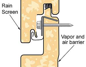
Drainage Cavity
The outer material is often referred to as a rainscreen, particularly
if it is a metal material that is not intended to be airtight
and is primarily intended to be the weathering surface that
screens the rest of the wall system from rain and other elements.
It may be attached in various ways that penetrate through
the air and water barrier and gypsum sheathing into the studs.
The space created between the rainscreen and the barrier-covered
sheathing is called the drainage cavity. It must have enough
space for moisture to properly drain out and still accomplish
air pressure equalization, which is important in windy conditions.
The drainage cavity is sometimes divided into compartments
that help maintain pressure equalization.
5. Rainscreens
The term rainscreens refers to the outer material in a wall system, usually when it is made out of metal cladding. There are several different metal cladding types:
Single Skin or Roll-Formed units.
This common type of metal cladding has very desirable design
characteristics. These materials provide variations in texture
from light striations to bold ribs, which can provide light
or bold textures. They can also be installed to run horizontally
or vertically.
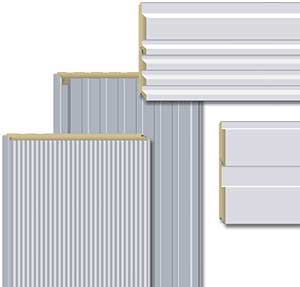
Foam Insulated units.
Metal cladding may also be an insulated composite (Figure
10) . Design characteristics of this metal cladding type include
high-performance pressure equalized joinery, and the ability
of the units to be curved to various radii. They also can
be installed in horizontal or vertical applications, using
both wide horizontal reveals and wide vertical reveals recessed
to the same plane as a standard detail. They integrate easily
with glass curtainwall and windows.
|
Thin Composite Metal Units
Thin metal composite walls consist of two layers of metal,
with a composite core that is either formed or fabricated
into a panel system. Some joinery systems have geometry that
is a pressure-equalized rainscreen. These composite walls
are created for superior flatness, wide modules, and grid
look. Design characteristics include crisp sight lines, smooth
curves, and a high-tech grid look.
Plate Systems
Plate systems are available in many types of designs. They
generally are used on medium or high-rise construction.
Custom Wall Systems
Custom wall systems are almost limitless in what can be accomplished.
When comparing the different types of rainscreens, it is important to remember that they serve several important functions. Beyond providing an outward appearance and wearing surface, they allow a wall system to drain liquid and to vent water vapor from external leakage, internal vapor diffusion or internal air leakage. In general, rainscreens allow ventilation behind the metal to help eliminate moisture in the drainage cavity. In a 1988 publication entitled, "Rainscreen Cladding, a Guide to Design Principles and Practice," by Anderson and Gill, two types of rainscreens are defined, backside ventilated, and pressure equalized.
Backside-Ventilated Rainscreens
According to the authors, "back-ventilated...claddings
are allowed to leak, and no deliberate attempt is made to
minimize the effects of wind by means of pressure equalization…large
quantities of rainwater penetrate the joints and run down
the reverse, hidden face of the cladding assembly."
Pressure Equalized
The second type of rainscreen is a pressure-equalized system.
Joseph Lstiburek, Ph.D, P.Eng., principal of the Building
Science Corporation, has studied wall systems in considerable
depth. He describes the most effective wall system as one
that prevents water from entering the wall cavity and wetting
the inner layers, while allowing air to enter and ventilate
the cavity. Proper design of the horizontal joint and the
air barrier in a pressure equalized rainscreen provides what
Lstiburek indicates is excellent performance, that being horizontal
joints that keep water out, while permitting air to enter
and help dry the cavity (Figure 11) . The vertical joints
in this system are continuously rear sealed, creating closed
vertical compartments in the metal cladding that help maintain
pressure equalization (Figure 12). This is critical for high-
wind areas and at the corners of buildings.
|
|

|
It is important to note that surface sealed (or wet-sealed) metal systems are popular but are not rainscreens. Relying on caulking or sealant, wet-sealed systems have minimal venting, rely on perfect installation, and act as a second vapor barrier. When comparing a dry-sealed rainscreen and a wet-sealed system, cost over the lifespan should be considered. Dry-sealed systems usually have a higher first cost, but when the cleaning costs and required replacement of the wet seals is factored into a 50-year life expectancy, the dry sealed system has a lower overall cost to the owner (Figure 14, Centria #35). Section view of wet-sealed systems and inherent problems of drainage and moisture entrapment.
6. Sustainability
For a wall system to achieve good and responsible design it should support sustainable or "green design". Some relevant key sustainable items related to metal wall systems include:
- Materials usage and recyclability
• Architectural metal has a high recycled content
• Architectural metal is 100 percent recyclable - Thermal efficiency for reduced energy use
• Insulation is located outboard of studs
• No reduced performance per ASHRAE 90.1
• HVAC requirements may be significantly reduced - Minimizes potential for water-related damages leading to long-term durability
- Lower maintenance and replacement requirements
According to John Boecker, faculty member of the U.S. Green Building Council's training seminars and member of a consulting group that provides LEED certification, "the most environmentally benign building material is that which you do not use." A single-component insulated composite foam panel is a complete wall system that comes engineered as a kit of parts that fits onto the building, eliminating large amounts of scrap generated by multi-component elements that are cut to fit on the job site.
7. Rainscreen Testing
As of 2005, there is no protocol for testing rainscreens and multiple-component wall systems in the U.S., although the American Architectural Manufacturers Association (AAMA) is working on a solution. Nonetheless, two elements of testing for water infiltration that leading consultants agree on is a working test pressure of 15 psf and to replicate the fact that air barriers are rarely installed without some perforations.
|
General Procedures
There are three recognized tests for water and air infiltration:
ASTM E-331 is a static test measuring water infiltration using negative pressure on the interior to pull water through the wall.
AAMA 501.1 is a dynamic test that tries to push water through the wall using applied wind pressure on the exterior.
ASTM − 283 is a static test that uses negative pressure to pull air through the wall.
These tests can be performed using a standard ten foot by ten foot testing chamber for a wall system (Figure 14).
|
Wind Testing
The chart below depicts the equivalent wind speed, pressure,
and water height rise. Most testing is done at very low pressures.
High-performance wall systems are tested at 15-psf pressure
with imperfect air barriers and no water infiltration.
|
|||||||||||||||||||||||||||
Air Barrier Imperfections:
When testing a rainscreen with a 100 percent continuous air
barrier behind the rainscreen, the pressure drop on the outer
wall is zero. However, due to construction
limitations, a perfect air barrier will not be established
on the job site due to penetrations in the wall construction.
There will remain unsealed side joints or improper fasteners
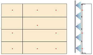
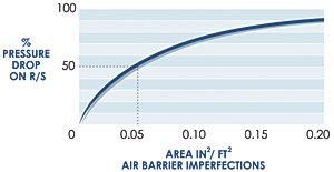
in the barrier. In this test chamber, nine three-quarter inch
diameter holes, which equal five square inches per 100 square
feet, were used to simulate the imperfect barrier. The horizontal
value is the amount of perforation in the air barrier (Figure
17). The vertical value is the percentage of pressure drop
on the rainscreen. With zero imperfections, there is no pressure
drop on the rainscreen. This is really a test of the air barrier,
not the rainscreen. At five square inches per 100 square feet
(the approximate value for unsealed gypsum sheathing) of perforation,
the findings indicated some systems had 50 percent of the
design pressure across the rainscreen. A pressure-equalized
rainscreen will offer enough venting to reduce this percentage
to less than one percent with five square inches per 100 square
feet of air barrier imperfection.
|
8. Details on the Importance of Superior
Air Barrier and Vapor Barrier Continuity
The following are important when designing and specifying exterior metal walls with superior thermal and moisture control:
Vapor drive and vapor barrier location
according to climate.
Vapor diffusion causes moisture to penetrate wall materials.
In certain climates, vapor barriers (perm ratings less than
1.0) are used to prevent vapor diffusion. Vapor pressure is
greatest at high temperatures and high relative humidity.
The greater the
vapor pressure difference from inside to outside, the greater
the vapor diffusion concern. In climates like the hot and
humid southeast U.S., the logical location for a vapor barrier
is outside the insulation and in cold climates, a vapor barrier
is required on the inside of the insulation. In moderate climates,
where the vapor drive is bi-directional−outside to inside
during summer, inside to outside during winter− a standard
vapor barrier is not recommended. Instead, a special vapor
barrier that varies its perm rating−low during the dry
winter, high during the humid summer−is recommended on
the interior of the wall assembly.
Multi-component wall systems combine
barriers.
Creating vapor barrier and retarder continuity is very difficult
to achieve on the interior of stud framing due to electrical
penetrations and discontinuities at the floor and ceiling.
To improve vapor barrier and retarder continuity, the Massachusetts
Building Code's suggested details combine the function
of the vapor barrier and retarder with the air and water barrier
in a rubberized asphaltic barrier located outboard of the
studs between rigid insulation and exterior gypsum sheathing.
In the hot and humid climates the same rubberized asphaltic
layer is placed over exterior gypsum sheathing located outboard
of the studs, with the insulation located within the stud
cavity.
Air and water barrier continuity
is the key.
The volume of moisture transported by airflow is 50 to 200
times greater than the volume of moisture transported by vapor
diffusion. Air from any small leak can travel throughout the
inside of a wall, dropping condensation, whenever the temperature
falls below the dew point. This moisture usually becomes trapped
and can lead to wall system degradation. Therefore it's
imperative that the air and vapor barriers be continuous.
Relocating the air and vapor barriers outboard of the stud
line is a big step toward achieving this continuity.
Superior wall performance should
always be sought.
Avoid the many hazards of thin wraps and rubberized membranes
by specifying and designing wall systems that provide superior
air, water, and vapor control performance. Further, use systems
that provide superior thermal performance with continuous
insulation that is not compromised by metal studs, penetrations,
or difficult details.
9. Wall Systems with Superior Performance
There are several different types of wall systems that are worth special attention.
Superior Wall System 1:
Outboard insulated panel and pressure
equalized rainscreen
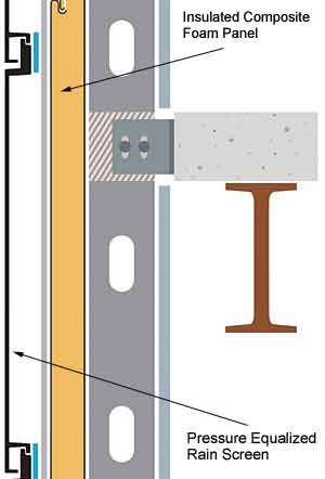
System 1 is a multi-component system with only two elements:
a pressure equalized exterior rainscreen and an insulated
composite foam panel backup (Figure 18). The exterior element
provides ventilation to the cavity, while limiting water infiltration.
It is tested at 15 psf and an imperfect air barrier. The insulated
composite foam panel provides:
- Integral vapor retarder
- Integral air barrier
- Integral water barrier
- ASHRAE rated insulation R values as high as 26.5. Key benefits of the System 1 insulated wall include:
- One company is responsible for the wall.
- Composite foam panels have 35 years or more of performance as an exterior wall panel.
- Functioning behind an excellent rainscreen will provide lengthy service.
- Studs are on the warm side of the insulation and less subject to corrosion.
- Continuity of vapor barriers.
- Functions in all climatic conditions.
|
Superior Wall System 2: Single Component
This system is a factory-assembled composite foam panel system
built as the entire
wall system (Figure 19). It is intended to be secured directly
to the building structure. It provides a fully integrated
approach to providing a weathering surface, vapor retarder,
water infiltration barrier, and air infiltration barrier.
Key benefits of this single component system include:
- Pre-finished exterior weather surface in manufacturer's selection of colors and finishes
- Integral water barrier by virtue of the sealed system materials.
- Integral air barrier sealed at all required locations.
- Integral vapor retarder by virtue of the sealed and finished interior surface.
- Insulation at various levels as needed for differing climates, as indicated in ASHRAE.
- Greater R-values than metal stud cavity insulation.
|
As indicated earlier in the rainscreen definition section, proper design of the horizontal joint can create pressure equalization.
This wall system has been tested using both the static and dynamic water tests. The tests results are excellent. With the interior sealant intermittently removed and at a 15 psf test pressure, there is no water infiltration. Intermittent removal of the sealant testing is consistent with the previous test protocol of testing with an imperfect air barrier.
Superior Wall Design Recommendations
The two superior performing wall systems presented eliminate
layers of components thereby minimizing scrap and labor. Other
building material factors to consider during the design phase
are the following:
- Establish air, water and vapor barriers behind the rainscreen
- Establish an air space behind the rainscreen
- Drain the air space at panel base, window, and door heads
- Establish perimeter trim seals to air and water barrier
- Use the right material in the right location
- Avoid materials with mold food
|
Window Selection
When selecting windows follow these guidelines:
- Use a window that integrate into the wall system
- Require testing to documented performance
- Tie window into the wall system air barrier
Risk Management
Multi component wall systems are complex to design and difficult
to properly install. When designing exterior metal wall systems,
consider reducing risk by:
- Limiting the number of suppliers and trades involved in the wall design and assembly.
- Using elements as rainscreens that have been tested with imperfect air barriers.
- Eliminating multiple component backup systems by using an insulated composite panel.
- Use a factory assembled composite foam panel system wherever possible.
Moisture management is key to a successful wall system. It is best achieved when a building is designed to meet the proper environmental criteria.