The Foundation of Durability
The next innovation in crawl-space ventilation
![]() Continuing Education
Continuing Education
Use the following learning objectives to focus your study while reading this month’s Continuing Education article.
Learning Objectives - After reading this article, you will be able to:
- Discuss moisture buildup in crawl spaces, the consequences of excess moisture, and how crawl-space ventilation protects the building and occupant health.
- Compare conventional foundation vent systems, their effectiveness, long-term performance, and health impact.
- Identify a new option/alternative for venting a foundation built over a crawl space.
- Define continuous foundation ventilation systems and their sustainable benefits.
- Describe several case studies of projects where continuous perimeter foundation vents were specified.
Every so often, a new way of building homes emerges that is so simple, so elegant, and yet so revolutionary that the mind can hardly grasp it.
Take the case of a continuous perimeter foundation vent system. This low-profile, honeycomb crawl-space venting system is placed between the concrete foundation wall and the wooden sill plate to provide passive airflow around and through the entire perimeter of the home’s crawl space. This eliminates the need for conventional vent boxes either in the concrete foundation or cut into the rim joist.
All images courtesy of Joto-Vent System USA, Inc.
Home from Stanwood, WA
“I’ll never go back to cutting vent holes into rim joists and foundations,” says Takeshi Kaneo of TK Home Design and Build in Bellevue, Washington, who has used the perimeter venting system in two of his projects. “I wish I had known it was available in the United States sooner.”
Not only does this venting system provide continuous and foolproof venting into and out of the crawl space, composite venting strips provide a capillary break between the concrete foundation wall and the wooden sill plate, eliminating the need for a pressure-treated wooden sill plate and preventing sill rot and sill breakdown from wicking moisture from the concrete foundation. Additionally, as a treated sill plate is not needed, neither is galvanized hardware.
The system has been used for more than four decades in Japan and is the most common crawl-space ventilation system used there.

All images courtesy of Joto-Vent System USA, Inc.
The latest innovation in crawl-space ventilation provides continuous airflow with no dead air pockets in the crawl space, eliminating the need for unsightly and troublesome openings in the foundation wall or rim joist.
Innovative Design and the Kobe Earthquake of 1995
Prior to the Kobe Earthquake in 1995—which measured 6.9 on the Richter scale, killed more than 6,000 people, and destroyed more than 400,000 buildings—many crawl spaces were vented in the conventional method using openings in the foundation wall, while others used the perimeter venting system. After the earthquake, some observers noted a difference in how each type of building fared.
“After inspecting the devastation, we found that homes using perimeter venting systems survived for two main reasons,” says Takashige Maebayashi, a Japanese-licensed architect and director of engineering and development for Joto USA. “The first reason is that the use of the continuous venting system doesn’t require cutting the foundation for crawl-space ventilation. Houses that used the conventional style methods naturally have weakened foundations and are more susceptible to damage. The second reason is that with the perimeter venting system the sill plate is separated from the foundation and so it won’t decompose, which aided in supporting a long-term structurally sound foundation.”

With every catastrophic disaster, building codes and practices tend to change. After the Kobe Earthquake in 1995 destroyed more than 400,000 buildings, the use of perimeter venting systems increased.

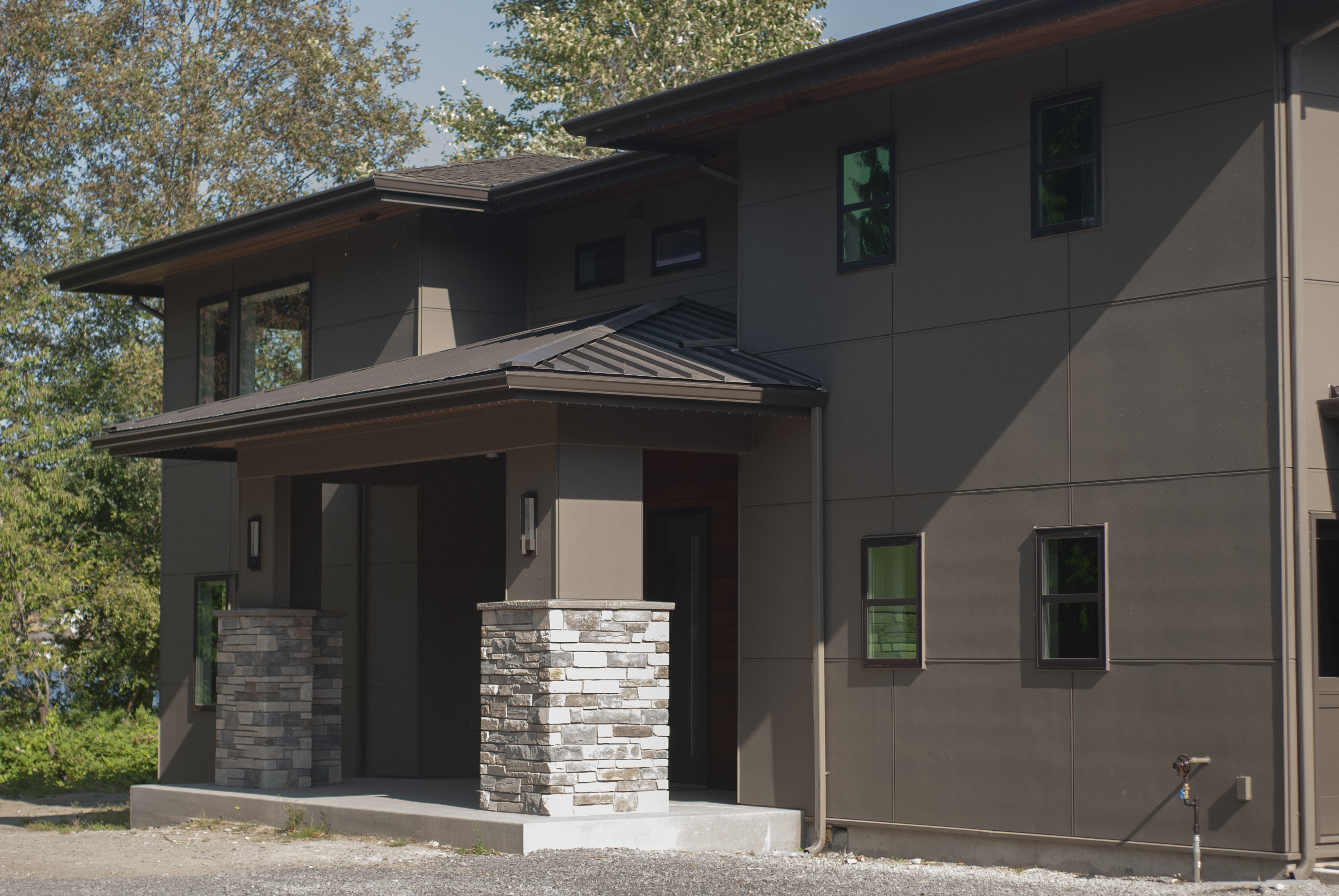
This house has a continuous perimeter vent system for crawl-space ventilation. The absence of vent holes in the foundation is a preferred aesthetic by some architects.
In the two decades following the Kobe Earthquake, adoption of the perimeter venting system has skyrocketed. One company alone has provided perimeter venting systems to more than 4.5 million new Japanese homes.
A Sleek Aesthetic
A final consideration is the sleek elegance of this venting system, allowing complete passive crawl-space ventilation with just a thin and nearly unnoticeable presence, and without the common—and some would say unsightly—large openings currently cut into foundations or rim joists every 8 feet or so to allow for airflow.
For architects, engineers, and builders in North America, however, while those holes cut into the foundation or rim joist ventilation may be ugly and even detrimental to the integrity of the foundation, the practice continues because “it’s the way things have always been done.”
Erik de Buhr, an owner and builder in Eugene, Oregon, and founder and co-executive director of a nonprofit that helps solve homelessness, sought out the new venting system as a solution to a design problem.
“While designing our house, I realized that our stem wall was going to be too short to use the standard plastic crawl-space vents,” he says, adding that he “wasn’t looking forward to using them anyway because, in my opinion, the vent boxes detract from the clean exterior look of the house and don’t do a very good job.”
So the questions arise: Is the conventional box venting method the only way to go? Is it the best way? Is there a better way? This course examines this innovative manner of passively venting a crawl space evenly and unobtrusively around the entire perimeter, and compares it with the traditional method of box vent openings to which most have become accustomed. Let the designer or builder be the judge.
We begin with why crawl space ventilation is so critically important.
How and Why Moisture Builds Up in Crawl Spaces
Providing ventilation under a raised foundation house is as old as the North American building trade itself. While some homes are built over basements, or more recently on grade-level concrete slabs, there are plenty of locations and soils and climates where separating the foundation of the home from the ground is the best design.
Consider raised homes built for centuries in the Northwest or Southeast of North America. Pilings set deep in the ground provide anchors for the raised foundation. While the temperature at the surface of the ground varies widely depending on season and climate, the temperature becomes less changeable and more moderate below the surface. This relatively warm below-surface ground temperature produces moisture, and this is the reason for the building practice of a raised foundation built up on a crawl space. While the soil below alternately gets wet, dries out, freezes, or unfreezes, the foundation raised above it remains unaffected. And with air flowing freely underneath the house, natural breezes carry away ground moisture. The raised design also allows easy access to plumbing, electrical, and mechanicals under the floor.
As building practices changed, the pilings on which the foundation sat became a reinforced and poured concrete foundation wall on which the foundation sat. To create the necessary airflow to keep moisture from accumulating, the code required holes in the foundation wall to allow air to freely move in and out of the crawl space. Screens or louvers were also required to prevent rodent intrusions.
Moisture in crawl spaces is a persistent problem. Moisture in the form of water can even enter a crawl space after construction through the vent holes.
The Consequences of Excess Moisture on Building Durability
While providing a method for passive ventilation under a raised home theoretically solves the moisture problem, the method itself can fail to perform. We will discuss the reasons for that shortly. But the consequences of moisture buildup under a home are alarming.
When moisture builds up in a crawl space, these damages to structure can happen:
- White wood rot fungus
- Mold
- Black mold
- Infiltration of insects, snakes, reptiles, and frogs
- Standing water
- Mushrooms
- Wet and moldy fiberglass (Insulation may be installed correctly, but when it gets wet, it gets heavy, pulls away, and grows stalactites.)
- Condensation on ducts
- Stalactites
- Wet walls
Consequences to Occupant Health from Crawl-Space Moisture Buildup
It’s not just the building that suffers when the crawl-space ventilation method fails. Occupant heath also suffers. While a miasma of troubles grows under the floor, the consequences trickle up to the home. They create or exacerbate:
- Poor air quality
- Allergies
- Asthma
Code Requirements
It’s clear that getting the air to move under the raised foundation to draw out the moisture in the crawl space is critically necessary, and the building codes reflect this by what is required in the codes. Some designers and builders call for mechanically moving the air in and out of the crawl space, or even conditioning the space, which are two more expensive options available for a house built on a crawl space.
For other designers and builders that rely on natural, passive ventilation, these are the requirements according to the International Building Code (IBC):
IBC 1202.4: Under-Floor Ventilation
Under-floor ventilation. The space between the bottom of the floor joists and the earth under any building except spaces occupied by a basement or cellar shall be provided with ventilation openings through foundation walls or exterior walls. Such openings shall be placed so as to provide cross ventilation of the under-floor space.
Openings for under-floor ventilation. The minimum net area of ventilation openings shall not be less than 1 square foot for each 150 square feet (0.67 square meters for each 100 square meters) of crawl-space area. Ventilation openings shall be covered for their height and width with any of the following materials, provided that the least dimension of the covering shall not exceed ¼ inch (6 millimeters):
- Perforated sheet metal plates not less than 0.070 inch (1.8 millimeters) thick.
- Expanded sheet metal plates not less than 0.047 inch (1.2 millimeters) thick.
- Cast-iron grilles or gratings.
- Extruded load-bearing vents.
- Hardware cloth of 0.035 inch (0.89 millimeters) wire or heavier.
- Corrosion-resistant wire mesh, with the least dimension not exceeding 1⁄8 inch (3.2 millimeters).
- Operable louvres, where ventilation is provided in accordance with Section 1202.4.1.2.
The continuous perimeter vent system has a net free ventilation area (NFVA) of 4.81 square inches per foot and as stated before is a two-part system that uses a covering (flashing) to cover the vent. This equates to 15 feet of the continuous perimeter vent creating 1⁄2 square foot of NFVA, or roughly the same as a typical box vent. The holes in the covering are 1⁄8 inch, in the least dimension, as stated above. Besides being better for bug control, it is also acceptable in the Wildland-Urban Interface (WUI) Fire Area throughout California.
From the 2018 IBC:
- 1202.4.1.1 Ventilation area for crawl spaces with open earth floors. The net area of ventilation openings for crawl spaces with uncovered earth floors shall be not less than 1 square foot for each 150 square feet (0.67 m2 for each 100 m2) of crawl space area.
- 1202.4.1.2 Ventilation area for crawl spaces with covered floors. The net area of ventilation openings for crawl spaces with the ground surface covered with a Class I vapor retarder shall be not less than 1 square foot for each 1,500 square feet (0.67 m2 for each 1000 m2) of crawl space area.
- 1202.4.2 Ventilation in cold climates. In extremely cold climates, where a ventilation opening will cause a detrimental loss of energy, ventilation openings to the interior of the structure shall be provided.
- 1202.4.3 Mechanical ventilation. Mechanical ventilation shall be provided to crawl spaces where the ground surface is covered with a Class I vapor retarder. Ventilation shall be in accordance with Section 1202.4.3.1 or 1202.4.3.2.
- 1202.4.4 Flood hazard areas. For buildings in flood hazard areas as established in Section 1612.3, the openings for under-floor ventilation shall be deemed as meeting flood opening requirements of ASCE 24 provided that the ventilation openings are designed and installed in accordance with ASCE 24.
State-by-State Exceptions
Many states have made changes to the building-code requirements for crawl-space ventilation and offer various exceptions. For instance, here is a section from the Washington State Energy Code on venting foundations and the exceptions available:
R408.2: Openings for under-floor ventilation. The minimum net area of ventilation openings shall not be less than 1 square foot (0.0929 square meter) for each 300 square feet (28 square meters) of under-floor area. Required openings shall be evenly placed to provide cross ventilation of the space, except one side of the building shall be permitted to have no ventilation openings. Ventilation openings shall be covered for their height and width with any of the following materials, provided that the least dimension of the covering shall not exceed 1⁄4 inch (6.4 millimeters):
- Perforated sheet metal plates not less than 0.070 inch (1.8 millimeters) thick.
- Expanded sheet metal plates not less than 0.047 inch (1.2 millimeters) thick.
- Cast-iron grill or grating.
- Extruded load-bearing brick vents.
- Hardware cloth of 0.035 inch (0.89 millimeters) wire or heavier.
- Corrosion-resistant wire mesh, with the least dimension being 1⁄8 inch (3.2 millimeters) thick.
Exception
The total area of ventilation openings shall be permitted to be reduced to 1⁄1,500 of the under-floor area where the ground surface is covered with an approved Class I vapor-retarder material and the required openings are placed to provide cross ventilation of the space. The installation of operable louvers shall not be prohibited. If the installed ventilation is less than 1/300 or if operable louvers are installed, a radon vent shall be installed to originate from a point between the ground cover and soil.
As indicated, in the State of Washington the standard code/ratio is 1/300. And for the most part, a continuous perimeter vent system does not have a problem reaching this ratio. However, other jurisdictions have their own requirements, so relevant codes need to be researched before specifying the continuous perimeter vent system.
Conventional Foundation Ventilation Systems

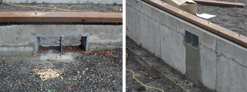
The conventional way of passively venting a crawl space requires many holes in the foundation or stem wall.
Currently, there are four options available for preventing moisture buildup in crawl spaces, including: 1) creating conditioned space (enclosed space), 2) mechanical ventilation, 3) vent boxes in the concrete foundation (passive ventilation), and 4) vent boxes cut into the rim joist (passive ventilation). The first two methods tend to be costlier and will require ongoing use of electricity. The passive method is addressed in this course. Passive ventilation takes advantage of the laws of nature. Air moves from cold to hot, and from wet to dry. In that way, if the crawl space is vented, the air beneath is in continuous motion.
In the conventional method of venting crawl spaces, openings are created in the foundation stem wall or rim joist at sizes dictated by the square footage of the house. Some designers may cringe at the sight of these openings in an otherwise sleek elevation, but in theory, these screened openings should do the intended job to allow air in and keep rodents, large insects, and other animals out. At times, though, reality overtakes theory, and the system fails or compromises the building.
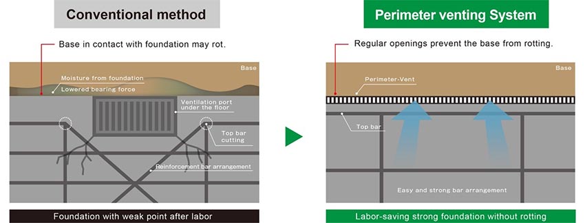
In the conventional method of venting a crawl space, the rebar is diverted to accommodate each vent opening.
Here are some weaknesses in the conventional venting system:
Concrete vent boxes can weaken the foundation. While rebar is used to strengthen the foundation wall against damage during earthquakes and other threats, the rebar is diverted at the vent openings. Simple logic indicates these areas are weaker than the surrounding reinforced concrete.
Vent box openings can present design-load challenges. For points where heavy loads on the building would be sitting right over an opening, the placement of the opening must be altered. That is usually handled in the engineering phase, but if that is missed, design and construction challenges could follow.
Vent openings can become backfilled with soil. Openings into the foundation wall near grade can and sometimes do become backfilled over time, decreasing the size of the opening, restricting airflow, and defeating its purpose.

Conventional vent openings can become blocked by vegetation.
Vent openings can be blocked by vegetation. Likewise, openings into the foundation wall can get blocked by vegetation growing up, and again the airflow is restricted. The dangers of moisture trapped in the crawl space (see above) can occur.
Vent screens can get cut during or after construction. The screening designed to allow airflow but keep out pests can easily get cut, either by other trades during construction or over time post construction.

The screening on conventional vent openings can be compromised by other trades.
Vents can become a tripping hazard. When foundation vents require a vent well that protrudes out from the wall, they can become a tripping hazard.

Conventional vent openings can become blocked by dirt and debris.
Unvented air pockets can develop. In a venting system where the openings are set every 6 or 8 feet apart, dead air pockets can develop in corners or between openings where the airflow is almost nonexistent. In those areas, moisture will build up and cause damage.

Conventional vent openings can leave dead, unvented spots.
The vents pose aesthetic concerns. While the practical weaknesses of boxy foundation vents are considerable, designers and architects often find the aesthetics of this method to be a jarring visual blemish on the exterior of an otherwise clean and streamlined aesthetic. The choice of a continuous perimeter foundation vent is often driven by this aspect.

Some architects believe that conventional vent openings detract from the exterior aesthetic.
Continuous Perimeter Foundation Vent System Characteristics

Continuous perimeter foundation vent systems are installed on top of the foundation or stem wall, providing a capillary break between the concrete and the wooden sill plate.
How It Works
As has been mentioned, this new crawl-space ventilation system utilizes passive, natural airflow. Unlike the traditional spot ventilation method, it allows maximum cross ventilation of airflow into the crawl space from the complete circumference of the building foundation, leaving no dead air pockets in the entire crawl space. The vent is installed between the concrete foundation and the sill plate, and it supports the entire weight of the house.
The horizontal vent is part one of a two-part system. The holes in the vents are slightly larger, which is slightly larger than the IBC code states as acceptable for airflow. The second part of the system is the covering (flashing) that is installed over the vent when the exterior siding is installed. This covering has 1⁄8 inch holes in it because some building jurisdictions like to see 1⁄8 inch holes to keep insects out. Also, the 1⁄8-inch standard is required by California if the vent covering is to be WUI certified, and that is why the holes in new perimeter venting systems are not 1⁄4 inch as stated in the code.
Compressive Strength

Testing indicates the vent system is stronger than the sill plate.
These vents are made of a composite material that may consist of calcium carbonate, and recycled plastics. The leading brand has an ultimate compressive strength of more than 56,000 pounds per lineal foot of vent. And when ICC-ES standards are applied, the vents can safely support 7,140 pounds per lineal foot. Wherever a wooden sill plate is trusted to hold the weight of the structure, the vent system can do the same. The wooden sill plate will be the controlling factor.
Testing
This brand has been evaluated as of May 2019 with an ICC-ES report. In addition, these systems have more than a 45-year track record of successful use in Japan. The perimeter vent system is the most common way crawl spaces and foundations are vented in Japan.
Sustainability
Because the vent is installed between the concrete foundation and the wooden sill plate, and thus the sill plate is not in direct contact with the concrete, IBC and IRC codes do not require treated lumber. With all treated sill plates eliminated from the specs, the opportunity arises for more build green points for the project.
Sizes
Perimeter vent systems generally comes in 6 inches wide for 2 x 6 and 2 x 8 framing. The covering (flashing) generally comes in 13⁄4-inch (45-millimeter) depth (protrusions) from the wall and may be is available in white and black. The covering may be available in a paintable galvanized steel.
Performance During Earthquake Testing

Testing indicates the wall is as strong with the perimeter vent system as without.
As mentioned earlier, this perimeter venting system was invented in Japan, where they used the same type of vents installed in the concrete as is used in the United States because the weak point in the foundation is where the concrete vent box is located during an earthquake. This is why the perimeter vent system sits on top of the foundation wall and is not set into the concrete to keep the strength of the concrete foundation wall.
In addition, the venting system on top of the foundation wall does not weaken the lateral resistance of the light-frame shear wall system. Shear wall tests indicate that the wall is just as strong with perimeter vents as it is without the vent.
According to test results from the renowned University of British Columbia Timber Engineering & Applied Mechanics Lab: “The walls with (a continuous perimeter venting system) had similar load-bearing capacity compared to the walls without (the perimeter venting system). On average, the difference between the two groups was 2 percent in peak load and 4 percent in deformation capacity. There was no significance in the vertical movement of the wall.”
New vs. Retrofitted Homes
This type of vent is for new construction or new additions only. It must be installed under the sill plate so it cannot be retrofit into an existing house.
Other Applications
In addition to crawl spaces, continuous perimeter vents can be used on the inside of the garage to provide airflow. For attached garages, non-vented pieces are installed to prevent air flowing from the garage into the crawl space. It is added here or in other locations on the foundation wall to keep the sill plate and stud height the same all around the foundation. It can also be used to separate the sill plate from the concrete to eliminate the treated sill plate and use just a standard sill plate.
Installation of Continuous Perimeter Foundation Vent System

Installation happens in two phases. The framers install the vent, and the siders install the flashing/cover.
Installation of the vent system will vary from the conventional building process, and there may be a learning curve in terms of phasing rather than the technical aspect of the installation itself. There are two parts to the system, and they are installed during two different phases of construction. The framers install the perimeter vent, which generally comes in 3-foot sections, before they install the sill plate. A few weeks later, when the siders are ready to install the exterior siding, the second part of the system is installed, the vent covering/flashing, which generally comes in 10-foot sections.
For the builder, one of the biggest benefits is that the complete perimeter of the crawl space is being vented instead of just the corners and every 8 to 10 feet of the foundation walls. This provides maximum cross ventilation and leads to better moisture management in the crawl space, thus prolonging the life of the wood under the house.
For the engineer, the perimeter vent system eliminates the need to calculate the loss of strength in the foundation due to the vent box holes in the structural concrete or rim joist.
For the architect, the biggest benefit is the overall finished clean look of the exterior of the house with no visible vent boxes. The homeowner gains confidence that his or her crawl space will be properly vented to prevent damage to the home and occupants.
AN ARCHITECT’S PERSPECTIVE

The perimeter venting system uses passive means to extract moisture from the crawl space.
John Gresseth is the founder and managing partner of John Gresseth Architects in Friday Harbor, Washington. He graduated from the University of Washington in 1970 with a professional degree in architecture. He has been a licensed architect since 1977. Gresseth has used a continuous perimeter vent system on several projects. He was asked about his experiences.
How did you hear about the continuous perimeter foundation vent system?
Gresseth: I initially saw it at the Seattle Home Show.
Why did you choose to use this system?
Gresseth: The system is very well detailed and effective. The installation results in a clean look and provides continuous venting throughout the crawl space.
The installation is different from what is typical for foundation venting. Did this cause any problems in the construction phase?
Gresseth: Other than initial skepticism on the part of the builders (because of unfamiliarity) installations went well. In fact, I was at a housewarming recently where the builder commented on how he thought it was a very nice system. There were no problems in our jurisdiction from code officials once I supplied test results provided by (the manufacturer).
You specified the premium cover of extruded aluminum rather than standard white for your projects. Why is that?
Gresseth: The standard cover comes only in white. In fact, we painted the vent covers in one of our jobs.
What is your overall impression of the system?
Gresseth: I think [the system] is a superior product providing great, continuous venting and a superior finish look.
CASE STUDY: RESIDENCE, SEATTLE AREA, WASHINGTON

For the wet and humid Pacific Northwest, the continuous perimeter venting system provided a good solution to several problems.
For a custom home in the Seattle area of Washington, a continuous perimeter venting system was chosen after the typical ventilation method was deemed unacceptable for several reasons.
“In this market, we don’t have a lot of options for venting crawl spaces,” says Brian Finney, a project manager residential construction industry.
What is typically found in the wet and rainy area are typical 8-inch x 16-inch boxes or rim vents, Finney explains.
However, such a venting system requires a buildup of 8 inches to accommodate the boxes. And whether that vent is in the stem wall or the rim, “that vent is a requirement in each and every jurisdiction so it’s got to happen,” Finney says.
In the area where Finney works, the topography includes a lot of sloped lots, and that creates a lot of grading obstacles to overcome.
With this particular build on a view lot, Finney had a target mark that he had to hit in height. Specifying the perimeter venting system allowed him to eliminate that 8 inches of foundation he would normally need for conventional vents.
“It doesn’t seem like that much, but in reality, you can accomplish a lot with 8 inches,” Finney says. “This system allows the house to sit low and have that low-sitting profile, not standing out of the ground too proud.”
Finney says the perimeter system “just makes your project look better from the curb. It’s a benefit to be able to look at the house and not have it too proud out of the ground or be looking at those vents.”
According to Finney, the venting function achieved with the perimeter system is also superior. “Typically, you’re looking through your plans and looking for the optimal place to put the traditional 8-by-16 vent,” he explains. “With those 8 by 16s being randomly placed, you can get the draw and the draft and the airflow, but the airflow isn’t continuous, and it’s not even. When disturbed, it starts to diffuse, and that flow isn’t really there like you would get with a continuous perimeter vent system.”
“And I didn’t have to worry about vent wells and keeping the grade of the land away from these vent pockets,” he adds. “So you’re not only meeting but exceeding the venting that’s required by jurisdictions.”
On the project, Finney also used the continuous vent system for the soffit. The system fit in well with the contemporary design and produced a clean look. “All the louvers are concealed so you just see a continuous trough up in the eaves. It has a really good look to it,” he says.
For building professionals who might want to specify a perimeter venting system, Finney suggests choosing a manufacturer that is very involved with the project and supports the architect with the design. Lead time and how quickly a manufacturer can get the product to the site are also concerns.
“For me, it was the only solution we had to accomplish what we had to accomplish here,” Finney says. “This is one of the best venting solutions for homes in really wet, damp climates where you want that house to breathe really well. It’s your truest, purest crawl-space vent.”
Conclusion

A continuous perimeter foundation vent system brings together both form and function.
Crawl-space ventilation is vitally needed for the durability of the building and the health and safety of occupants. Failure to provide an adequate ventilation method leads to mold, fungus, rot, and pest invasion, as well as poor air quality in the home and breathing problems. The standard method of venting crawl spaces has many weaknesses. The vent boxes can become clogged, the placement of them may leave pockets of dead air where no ventilation occurs, and they can be unsightly. An innovative continuous perimeter foundation vent system can be a superior alternative. As the composite material of the vent systems sits between the foundation wall and the wood sill plate, there is no need for a treated sill plate. The system provides even and consistent ventilation around the entire perimeter of the home and uses the laws of nature to create a highly effective but passive ventilation system. As North America becomes aware of this continuous perimeter foundation vent system that is already in millions of Japanese homes, it may likewise well become the dominant crawl-space venting system in the future.
Kathy Price-Robinson writes about building and architecture with a focus on adapting to climate change. www.kathyprice.com