Embracing the Timber Age
Suitable vapor-permeable water-resistive-barrier and air-barrier membranes, roof underlayments, and flashing accessories can deliver high-performance enclosures for cross-laminated timber buildings
![]() Continuing Education
Continuing Education
Use the following learning objectives to focus your study while reading this month’s Continuing Education article.
Learning Objectives - After reading this article, you will be able to:
- Explain the benefits and growing popularity of cross-laminated timber (CLT) buildings.
- Recognize CLT’s unique sensitivity to moisture and how specially designed building enclosures are required to support building longevity and high performance.
- Review options for attaching various cladding components to the CLT panels.
- Describe best practices for designing and installing water-resistive barriers (WRBs), vapor retarders, and air barriers (ABs) in CLT wall and roof cladding systems.
- Review best practices for detailing CLT roof assemblies of varying slopes.
The following article is adapted from VaproShield Mass Timber Building Enclosure Design Guide with permission from the author and copyright holder, RDH Building Science, Inc. Refer to the original published content, inclusive of Limits of Liability and Disclaimer of Warranty, at https://vaproshield.com/mass-timber.
Driven by climate change concerns and sustainable design trends, structural wood is slowly but surely gaining traction. In fact, the worldwide market for cross-laminated timber (CLT) is expected to grow at a compound annual growth rate of approximately 9.1 percent over the next five years, reaching $980 million by 2024, states the Selbyville, Delaware-based market research firm Market Study in its “Cross-Laminated Timber Market Share” report.

All images, figures, and details courtesy of VaproShield and RDH Building Science
“This is the beginning of the timber age,” declares Andrew Waugh, RIBA, founder and director, Waugh Thistelton Architects, London, in a Dezeen article on this noted trend. “Building in wood is super fast, super accurate, and also makes the most amazingly beautiful spaces.”
Waugh claims that a CLT structure can be constructed 50 percent faster than a concrete building, requires fewer deliveries to the site, and provides a more pleasant environment for construction workers.
Architect Alex de Rijke, whose London-based firm dRMM has designed a few dozen CLT buildings, agrees, saying, “CLT is the future of construction. Timber is the new concrete.”
In an Economist video report titled “Wooden skyscrapers could be the future for cities,” Michael Ramage, Ph.D., director, Cambridge University’s Center for Natural Material Innovation, even goes so far as to say, “I think it’s very realistic to think that someone will build a wooden skyscraper in the coming years. Wooden skyscrapers could be the future for cities. There is a lot of potential that’s unrealized for using timber at a very large scale.”
Although the CLT building trend is stronger overseas, North America is coming on board with a 250,000-square-foot mass timber manufacturing plant going up in Spokane Valley, Washington, and another 227,000-square-foot CLT plant under construction in Dothan, Alabama.
While the potential is exciting, this fairly new renewable building type brings along with it a unique set of building enclosure challenges.
As a moisture-sensitive material, wood is slow to dry if wetted due to its hygric mass. Furthermore, wetting for prolonged periods can result in dimensional changes, moisture damage, and microbial growth. As a result, keeping CLT products dry during construction and throughout the building’s service life is critical. The speed at which CLT panels may be erected also creates unique field challenges where CLT panels are exposed to the elements for periods of time while awaiting cover.
Filling this unique niche of providing water-resistive-barrier (WRB) and air-barrier (AB) membranes and roof underlayment, very few technologies are ideally suited for the challenges specific to mass timber construction.
One such technology is vapor-permeable sheet membranes that simultaneously manage bulk-water infiltration while allowing for accelerated drying of the underlying materials. As a self-adhered WRB that bonds directly to wood substrates, no primers are required, so the membrane installation can proceed simultaneously with the CLT panel erection process. This technology also lends itself to WRB/AB pre-application, taking advantage of the prefabrication process inherent to CLT panel construction, and the quality control and weather protection that shop fabrication can provide.

Figure 1-2
At the Hawker Architects-designed First Tech Credit Union in Palo Alto, California, a cross-laminated timber (CLT) floor is supported by a glue-laminated timber structure.
Mass Timber
Before delving into the specifics of how to properly detail a CLT enclosure, some background on this newer building material is helpful.
Modern mass timber buildings are constructed of engineered wood products, often manufactured from multiple layers of sawn lumber, attached to form a solid panel, beam, or column. By forming solid wood sections, mass timber differs from the conventional, lightweight wood-framed construction that has long dominated the low-rise residential construction market in North America.
Among the mass timber materials known for their sustainable, renewable properties, CLT is the most popular. These panels offer strength, rigidity, and dimensional stability, making them ideal for floor, wall, and roof applications. CLT’s panelization potential also lends itself to streamlining the construction process and dramatically shortening the construction schedule while employing less labor
A number of other mass timber products widely used across North America offer similar benefits to CLT. They include nail-laminated timber (NLT), dowel-laminated timber (DLT), interlocking cross-laminated timber (ICLT), glue-laminated timber (GLT), vertically laminated veneer lumber (LVL), and laminated strand lumber (LSL). Multiple mass timber products can be used in the same building. For instance, Figure 1-2 shows an example of a CLT floor supported by a GLT structure.
While the primary focus of this course is CLT building enclosure design, much of the information applies to other types of mass timber products as well.
This course covers best practices for the design and construction of high-performance CLT wall and roof assemblies using suitable vapor-permeable WRB and AB membranes, roof underlayments, and flashing accessories in moderate to cold North American climates, including International Energy Conservation Code (IECC) Climate Zones 4 through 8. While CLT assemblies in warmer climates are not covered, these building enclosure products may still provide solutions for a successful enclosure design in these regions. Of course, these products can also be used with many other forms of mass timber, wood-framed, and conventional construction methods following similar installation techniques and detailing.
CLT Building Enclosure Design
The building enclosure, also known as the building envelope, separates interior building spaces from the exterior environment. In the context of CLT mass timber construction, the enclosure may be composed of vertical panels at exterior walls and horizontally laid or sloped panels at the roof. Interior floors may also be constructed with CLT or other panelized mass timber products. The internal mass timber structure may be provided by GLT, LVL, or similar structurally engineered wood products in a post-and-beam layout. Of course, not all mass timber projects must be constructed exclusively with wood products, and many hybrid construction combinations are possible, such as a structural concrete or steel core with a CLT enclosure, or a mass timber structure with a more traditional framed wall enclosure, as shown in Figure 2-2.

Project: First Tech Credit Union, Architect: Hacker Architects
Over its service life, the building enclosure is subjected to environmental loads of water, air, heat, and water vapor in addition to other loads, such as fire, smoke, light, sound, and insects. The enclosure must also counteract lateral wind loads and provide support of its own weight and other vertical loads if it is load bearing. These loads are transferred back to the building’s primary structure. Thoughtful design of the building enclosure considers all loads imposed on the enclosure over its service life, but this course will focus on controlling the water, air, heat, and water-vapor loads that act on the enclosure.
While CLT panels can be designed to meet the anticipated structural loads, CLT alone is not capable of adequately controlling air, water, heat, and water vapor. Thus, CLT must rely on an assembly of materials and other components to meet the building’s performance expectations. Performance can have a variety of meanings, but in the context of this course, it demonstrates a building enclosure that will effectively manage water (both liquid and vapor), reduce the building’s need for heating and cooling energy, and minimize the unintentional exchange of air between the interior and exterior environments.
Design and performance considerations for CLT enclosures differ from those of more traditional lightweight or mass concrete enclosures. CLT has unique physical properties, including its moisture sensitivity, relatively high capacity to store moisture, and relatively low vapor permeability.
Environmental Loads
The outdoor environment will vary depending on climate and local site conditions, and the indoor environment will differ by building use and occupant behavior. Thus, climate, microclimate, site conditions, and building use and operation are all important considerations when evaluating the environmental loads acting on the enclosure. Liquid water—predominately rainwater, but also snow melt and runoff—is typically the most critical environmental load. Other environmental loads—air, heat, and water vapor—are caused by differences between the indoor and outdoor conditions.
Water
With a higher sensitivity to moisture, rainwater exposure is a major issue with wood products.
If water contacts CLT surfaces for a prolonged period, particularly if exposed at the wood’s end-grain, the wood panel may absorb water, increasing its moisture content. Wood expands and contracts with changes in moisture content, so wetting of CLT will cause dimensional changes, potentially opening up gaps between laminations and panel interfaces that can adversely affect the aesthetic qualities and long-term performance of CLT. When dimensional changes occur too quickly, this can also cause CLT surface checking or cracks, which may allow water to penetrate further into the panel or cause visual irregularities if exposed to view. Prolonged exposure to moisture may also cause decay, microbial growth, corrosion of metal fasteners and connections, and potential damage to the interior finish if the panel is intended to be exposed. Limiting the CLT exposure to water during both construction and building service can reduce these risks.
In North America, the amount of annual rainfall can vary from low in desert and arid climates to more extreme levels in coastal regions. Rainfall levels can be exacerbated by high wind speeds resulting in wind-driven rain (i.e., driving rain). Wind speeds generally increase with height; thus, taller wood buildings made possible by CLT and other mass timber innovations are likely to see greater water loads than traditional wood-framed structures.
When rain falls can be as important as how much rain falls. This is because the seasonal distribution of precipitation can affect the drying potential of the enclosure after a wetting event. For example, a heavy rainfall followed by colder temperatures and/or high humidity levels provide little opportunity for drying. This consideration can have a significant impact on CLT panels that may have been erected but are not yet properly protected from construction-phase moisture.
While wall-cladding and roof-finish elements in a sloped roof application are responsible for shedding liquid, water is expected to bypass these elements at some point during the building’s service life due to natural deterioration of the materials or construction defects.
Additionally, some cladding and finish systems are designed in a discontinuous manner, such as open-joint cladding systems. As a result, a WRB or roof membrane/underlayment is necessary to protect the CLT, structure, and interior finishes from water ingress. A number of products are designed to serve this function by resisting bulk-water infiltration, with select products also offering extended UV and high-temperature stability.
Air
Air movement across the building enclosure is caused by a pressure differential between the inner and outer enclosure surfaces. This difference can usually be attributed to a combination of wind, the stack effect, and mechanical ventilation systems.
A continuous AB is a requirement of both the 2018 International Energy Conservation Code (IECC) and the National Building Code of Canada to control airflow across the enclosure. Limiting this airflow both inward and outward, has significant performance benefits, such as reduced energy consumption for building heating and cooling, improved occupant comfort by limiting drafts, reduced risk for interstitial condensation from moisture-laden air, and minimized transfer of other undesirable substances, such as sound, smoke, fire, and pollutants.
The AB is not a single component or material, but rather requires a system of materials, components, and assemblies that provide continuous air control throughout the building enclosure. Newly manufactured CLT panels may be shown to be impermeable to air when tested in a laboratory setting. However, CLT panels will rarely remain airtight over the course of their transportation, construction, and service life due to potential dimensional changes that may cause delamination and/or cracks to form, as stated in the Canadian-based forest sector research and development firm FPInnovations’ CLT Handbook (see Figure 2-5).

Figure 2-5
Small gaps between CLT laminations may not be completely airtight, thus requiring a separate AB membrane.
AB continuity at joints and interfaces of erected CLT panels must also be considered for a complete AB system. An AB membrane over the CLT panel or the use of flashing/tape products at these interfaces are required for the long-term airtightness of the enclosure.
For an AB to be effective, it must be impermeable to air, continuous, stiff, strong, and durable.
Heat
Heat will flow across the building enclosure when there is a temperature difference between the interior and exterior environments—the greater the temperature difference, the greater the thermal load. Thus, the heat or thermal load tends to be more influential in colder climates where the outdoor temperature dips below indoor temperatures throughout much of the year. Insulation is an essential component for energy-efficient buildings in most, if not all, North American climate zones. Selection and placement of the insulation can also improve occupant thermal comfort, provide a buffer from outdoor noise, and help manage condensation risk within the CLT enclosure.
CLT panels contribute to the assembly’s thermal performance because wood has a relatively low thermal conductivity when compared to other common structural materials such as concrete and steel. Most building codes across North America typically reference some version of the IECC, American Society of Heating, Refrigerating and Air-Conditioning Engineers (ASHRAE) 90.1, or the National Energy Code of Canada for Buildings (NECB) to set the minimum required level of insulation. Minimum insulation requirements generally fall within the R-15 to R-31 (RSI 2.6 to RSI 5.5) range for walls, and R-29 to R-48 (RSI 5.1 to RSI 8.5) for roofs. However, project-specific performance requirements may require greater levels of insulation than that required by code.
The thermal resistance of wood per inch varies based on moisture content and species, but for most commonly used North American softwood species, a thermal resistance of R-1.2 (RSI 0.21) per inch can be used, according to ASHRAE’s Handbook: Fundamentals. Thus, a five-ply, 55⁄8-inch thick CLT panel can be expected to contribute R-6.8 (RSI 1.9) to the enclosure assembly’s thermal performance. In most scenarios, the thermal resistance of the CLT panel alone will not be great enough to meet the required thermal performance of the assembly, and additional insulation will be needed. It is typically desirable to locate insulation outboard of the CLT to keep the CLT panel closer to the indoor temperature, minimizing condensation risk and limiting temperature and relative humidity fluctuations that may result in dimensional cycling of the CLT.
When a more highly conductive element, such as metal, bridges the insulation layer, it creates a path of lower resistance to heat flow. This path is commonly called a thermal bridge and will degrade the thermal performance of the insulation layer and overall assembly thermal performance. For CLT assemblies, it is common to locate the insulation exterior of the CLT, keeping the large structural connections inboard of the insulation layer. Thus, thermal bridges at CLT assemblies tend to result from a need to transfer wind loads and cladding loads back to the structure. Cladding and roof attachments/fasteners can have a significant impact on the thermal performance of the enclosure and can vary widely based on the system used. Generally, more thermally efficient options for these attachment points rely on less thermally conductive materials such as stainless steel, fiberglass, and/or intermittent attachments through the insulation, such as clips or fasteners, in lieu of continuous metal furring, according to RDH Building Science’s Cladding Attachment Solutions for Exterior Insulated Commercial Wall Assemblies. Two examples of thermally efficient cladding attachment solutions are shown in Figures 2-6 and 2-7. The attachment method will depend on the type of insulation used. Additionally, sealing may be required for some cladding attachment components where the attachments penetrates the WRB and AB membrane.

Figure 2-6
Mineral-fiber insulation is being installed between vertically oriented fiberglass girts.

Figure 2-7
Vertical wood furring with long-screw fastener attachments and rigid mineral-fiber insulation are installed over a self-adhered WRB/AB.
The mass of the CLT panel can also impact the thermal performance of the assembly by moderating heat flow through thermal storage. Depending on climate and other building factors, this thermal storage and throttling effect may reduce both annual and peak heating and cooling requirements, particularly in warmer climates with large daily temperature variations. Building codes that reference the IECC or ASHRAE 90.1 may credit this thermal mass effect with less-stringent prescriptive insulation requirements for mass wall and floor assemblies. A CLT assembly may exceed the minimum heat capacity required by IECC/ASHRAE 90.1 to meet the definition of a mass wall or floor. However, this will largely depend on the thickness of the panel, the wood species used, and code interpretations by the local governing jurisdiction.
Vapor
Water vapor molecules diffuse through materials from areas of high concentration to low concentration (i.e., from high humidity to low humidity). The resulting “vapor drive” can be an important consideration in the design of CLT enclosures. An accumulation of water vapor in the CLT assembly can result in interstitial condensation and/or excessive moisture uptake by the CLT. In most applications, the resulting direction of the vapor drive is from the warm side to the cold side of the enclosure such that in colder weather, the direction of the vapor drive is from indoors to outdoors. It is important to consider that the direction of the vapor drive may switch throughout the year as seasons change. However, vapor diffusion through most materials is a relatively slow process. Therefore, the more prevailing environmental conditions are most often considered. Additionally, depending on the space-conditioning needs, some interior environments may not subscribe to this rule of thumb and should be carefully considered during enclosure design.
While controlling air leakage across the enclosure is an effective means of managing water vapor, providing a separate vapor retarder is often also required to moderate the diffusion of water vapor across the materials within an assembly. The 2018 International Building Code (IBC) defines three classes of vapor retarding materials. At typical indoor humidity levels, the permeance of a three-ply, 31⁄2-inch CLT panel is between 0.05 to 0.6 U.S. perms (3 ng/Pa·s·m2 to 35 ng/Pa·s·m2) and thicker CLT panels are even less permeable, corresponding to a Class 1 or 2 vapor retarder.
When insulation is located entirely outboard of the CLT panel in cold, heating-dominated climates (i.e., ASHRAE/IECC Climate Zones 4 through 8), a separate vapor retarder is likely not necessary and is often not advisable. Omitting the vapor retarder allows the panel to dry to the interior as needed from seasonal wetting or construction.
WRB and AB sheet membranes, roof underlayment sheet membranes, and most flashing membranes should be vapor permeable to allow for some seasonal drying of the CLT panel. In these scenarios, it is also beneficial to use exterior insulation that is vapor permeable to allow drying to the exterior environment and avoid trapping vapor behind the insulation, as shown in Figure 2-8.

Figure 2-8
These figures show the difference between vapor-permeable exterior insulation (left) and vapor-impermeable exterior insulation (right) over a vapor-permeable membrane. Vapor-impermeable insulation can impede the drying of moisture stored in the outer CLT laminations.
Fire Protection
While fire protection is not the focus of this course, the CLT assembly’s combustibility may need to be considered to meet local building- and fire-code requirements. Often, the CLT itself will meet the required fire rating for the assembly. However, in some cases, an additional noncombustible thermal barrier may be required, such as exterior gypsum sheathing. In these instances, some products can be applied directly to the gypsum sheathing, similar to a typical installation over a framed wall.
In taller CLT buildings, the combustibility of the WRB membrane may also need to be considered. For construction exceeding 40 feet, Section 1402.5 of the 2018 IBC requires that CLT wall assemblies with a combustible WRB membrane are tested following NFPA 285 procedures to demonstrate conformance with fire performance requirements. The code currently does list exceptions for the testing requirements where the assembly is deemed to comply if the WRB is the only combustible component and has: 1) a peak heat release rate (HRR) of less than 150 kW/ m2, a total heat release of less than 20 MJ/m2, and an effective heat of combustion of less than 18 MJ/kg when tested per ASTM E1354; and 2) a flame-spread index of 25 or less and a smoke-developed index of 450 or less when tested per ASTM E84.9.
It should be noted that CLT construction practices are still relatively new in North America, and codes are continuously being updated to accommodate more prescriptive paths to CLT assembly fire compliance. This course recommends that project-specific fire-protection requirements are confirmed with the local jurisdiction having authority.
Termite and Pest Protection
In areas where termites and other wood-burrowing pests are prevalent, local codes may require protective measures for insect damage at CLT. These measures can be especially important at exposed areas of CLT and at grade where CLT is in contact with the foundation. To protect against termites and other pests, pest-sensitive CLT areas can be preservative treated and termite soil barriers introduced into the foundation design, such as termiticide soil treatments and separation membranes between the foundation and CLT. Regardless of the local termite risk, pest-control measures, such as insect screens at cladding openings and separation membranes at footings, are best practices in all regions.
CLT Wall Design and Best Practices
Now that a number of important building enclosure design principles have been established, they can be applied to CLT wall and roof assemblies.
The two options available for CLT wall assemblies in cold climates (i.e., Climate Zones 4 through 8) are closed-joint cladding and open-joint cladding (see Details 1 and 2). Both assemblies rely on a rainscreen strategy for managing rainwater, and in some North American regions, this is known as a drained and ventilated strategy, writes John Straube, Ph.D., principal, RDH Building Science, Toronto, in his Rain Control in Buildings white paper.
In a CLT structure, exterior cladding surfaces, flashings, and enclosure projections shed and deflect most of the incident rainwater. Incidental water that bypasses the exterior cladding of a rainscreen system is then managed by the following means:
- The weather-resistive barrier that serves as a drainage plane. Either a self-adhered WRB/AB or a black, UV-stable WRB/AB may serve as the membrane in the assemblies shown in Details 1 and 2.
- A clear air gap to allow water to drain. This air gap is also ideally designed to allow ventilation to improve the drying potential for moisture contained in the drainage cavity and at the backside of the cladding material.
- Deflection mechanisms such as flashings to drain water back to the exterior.
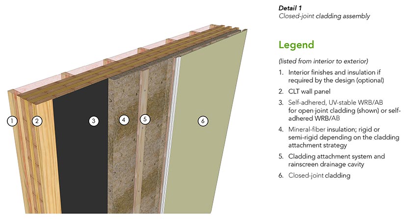
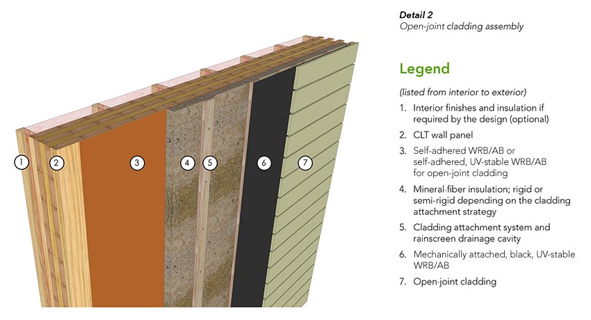
In these assemblies, the WRB also functions as the AB. The wall assemblies are exterior insulated with vapor-permeable mineral-fiber insulation to permit outward drying. If a vapor-impermeable insulation type is used, the assembly should be carefully evaluated by a design professional to ensure the wall design does not increase risk for moisture accumulation within the wall assembly.
In some cases, batt insulation may be added inboard of the CLT panel if required for sound attenuation or to improve the thermal performance of the assembly. However, the amount of interior insulation must be carefully balanced with the exterior insulation. Again, the interior insulated assemblies should be evaluated by a design professional to minimize the risk that condensation may form within the assembly.
For the open-joint cladding system shown in Detail 2, a sheet of black, mechanically attached WRB/AB is provided directly behind the cladding material and attached to the vertical furring. This serves to protect the insulation, the WRB, and other UV-sensitive components from UV rays. It also functions as an additional drainage plane immediately behind the cladding to shed the increased water load resulting from the open cladding joints.
Cladding Attachment Considerations
Cladding attachment penetrations through the WRB/AB membrane require careful consideration. As discussed earlier, cladding attachments can impact the thermal performance of the assembly as well as disrupt the WRB/AB if not carefully designed.
The four most common cladding attachment systems are a long screw with wood furring strips, clip and rail system, vertical girt, and horizontal girt.
Long screw with wood furring strips: Long screws through the insulation can be a cost-effective and thermally efficient option for the attachment of light- to medium-weight claddings. With this system, the cladding is attached to treated vertical wood furring strips placed against the face of a rigid mineral-fiber insulation. The furring strips are fastened back through rigid mineral-fiber insulation to the CLT panel. Additional detailing is typically not required where the fastener penetrates the WRB/AB.
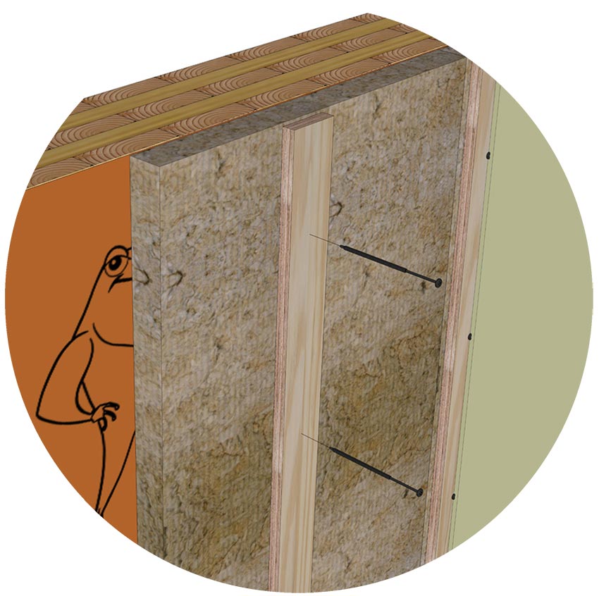
Figure 3-1
Long screw with wood furring strips
Clip and rail systems: The cladding is attached to vertical or horizontal metal girts. The girts, or rails, are attached to intermittent clips that bridge the insulation and are attached to the CLT structure. The insulation may be rigid or semi-rigid mineral fiber. However, semi-rigid insulation is typically easier to fit around the clips. Additional detailing is typically not required at clip-fastener penetrations through the WRB/AB or when the clips are installed tight to the membrane. However, when clips are not installed snug to the wall, the gap created behind the clip can trap water, increasing the risk for water ingress at fastener penetrations. A neoprene shim or silicone sealant are used at fastener locations to seal around the fastener in these scenarios.
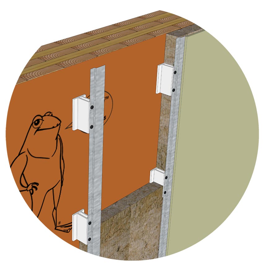
Figure 3-2
Clip and rail systems
Vertical girt: Vertically oriented girts are a common form of cladding attachment with rigid or semi-rigid mineral-fiber insulation types. Continuous metal girts significantly degrade the performance of exterior insulation, but more thermally efficient girts made of less thermally conductive materials are available. Similar to the clip and rail system, girt-fastener penetrations through a WRB/AB do not typically require additional detailing if the girt is installed tight to the wall. Where girts are not tight, a neoprene shim or silicone sealant is used at fastener locations to improve the seal at fastener penetrations.
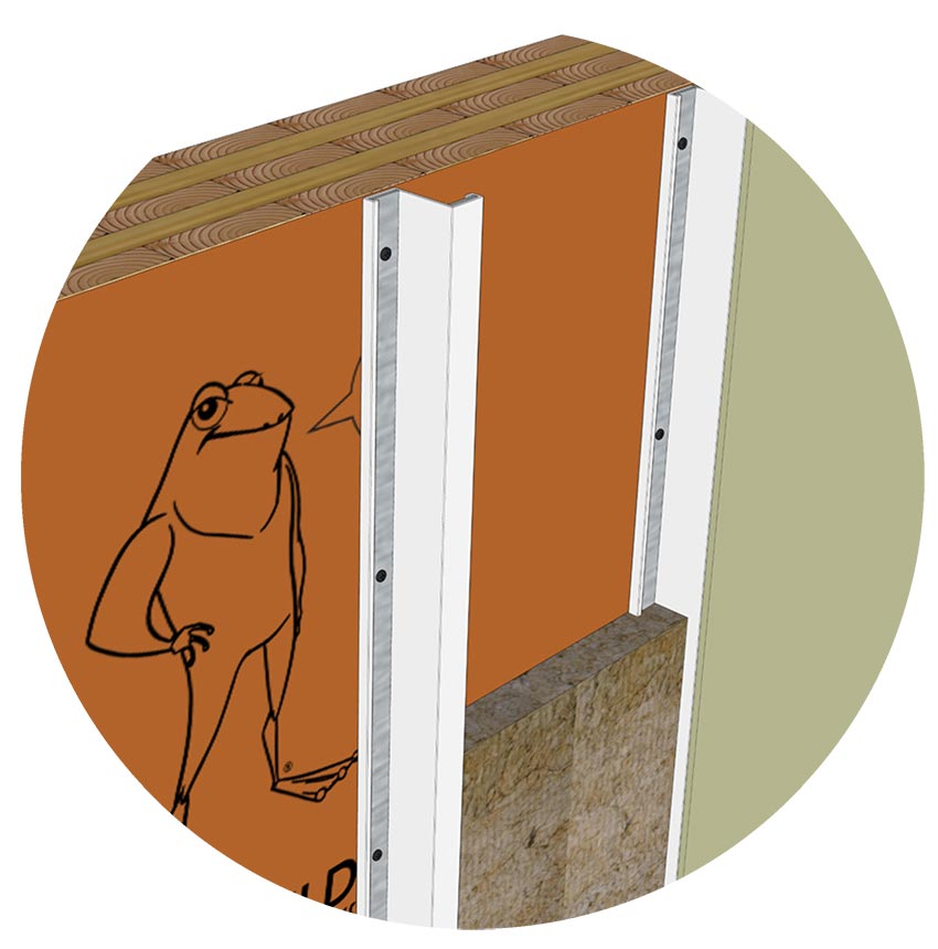
Figure 3-3
Vertical girt
Horizontal girt: Continuous horizontal girts can significantly degrade the performance of exterior insulation unless non-metal girts are used. Horizontal girts without flutes or perforations installed tight to the WRB may block the drainage path at the WRB plane. Some systems require that the horizontal girts are shimmed with a barrier to provide a continuous drainage plane and to seal around girt fastener penetrations through the membrane. Rigid or semi-rigid mineral-fiber insulation types can be used with this attachment approach.
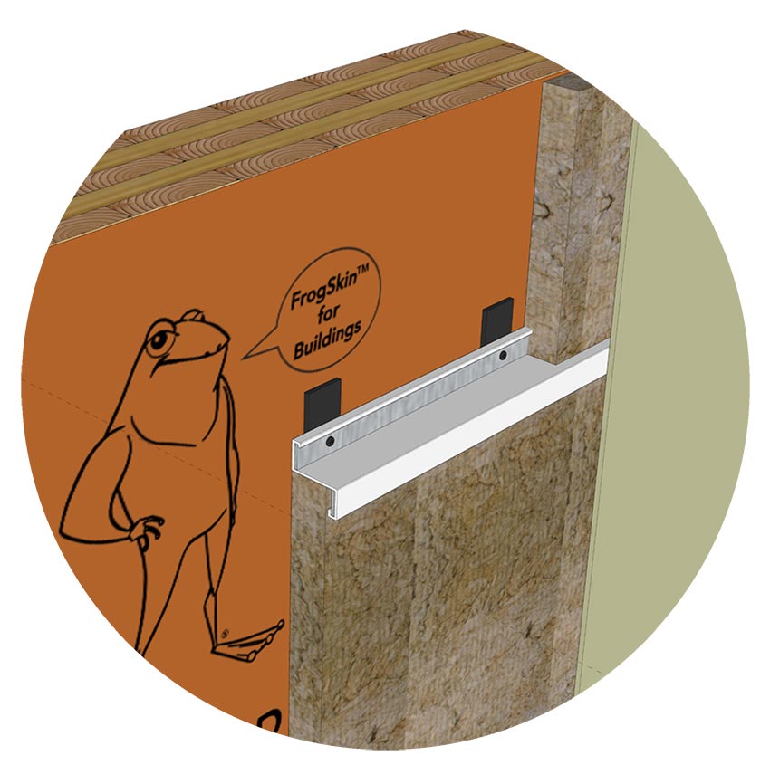
Figure 3-4
Horizontal girt
Window Rough Opening Detailing
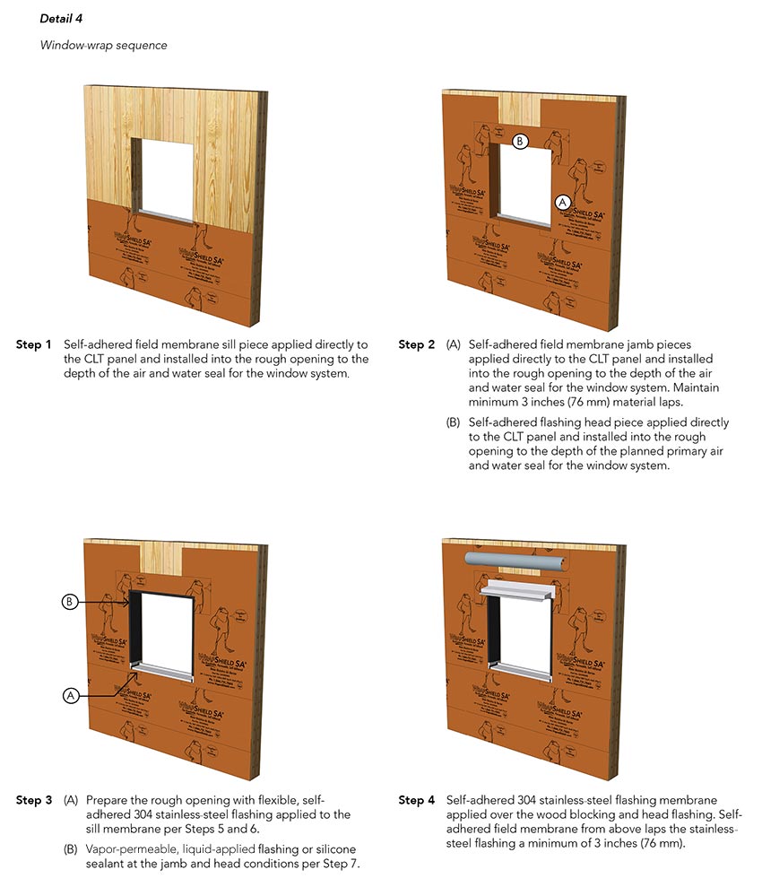
Shown in Detail 3a through 3d are typical window rough opening details. The opening wrap sequence, including integration with the WRB and AB membrane at the wall area field, is shown in Detail 4, window wrap sequence.
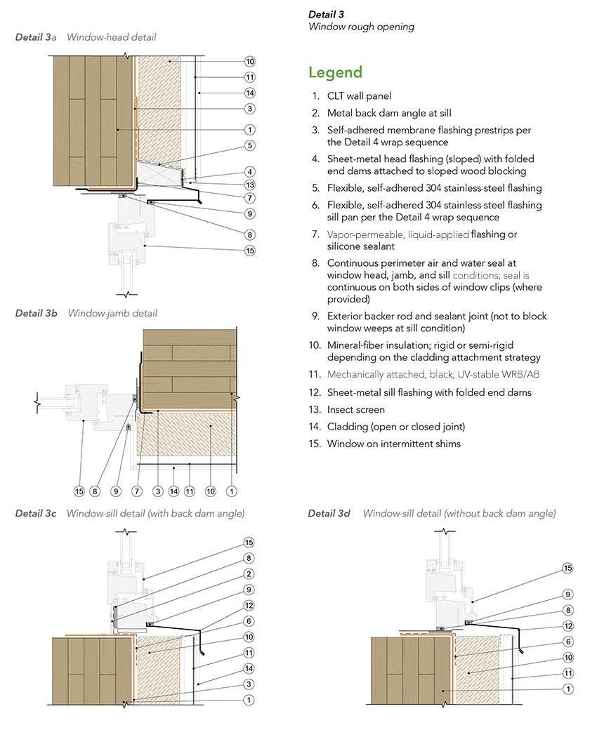
The interface where the window system meets the CLT panel is important because it can be a common source for water leakage if not designed and constructed appropriately. Appropriate detailing to provide continuous protection against water and air leakage requires that the WRB is flashed into the rough opening and a continuous air and water seal (typically a backer rod and sealant joint) is provided around the window perimeter.
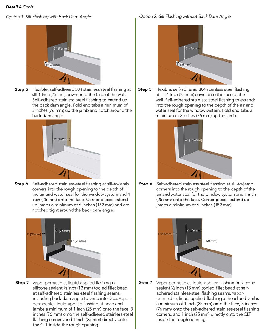
Best practice in some markets may dictate a metal back dam angle at the rough opening sill to form a sill pan. This angle may also serve as the structural attachment point for the window sill to avoid fastener penetrations down through the rough opening sill. Details for both a sill with a back dam angle and without a back dam angle are shown in Detail 3c and Detail 3d.
A sloped wood nailer is shown above the window as a thermally efficient attachment method for the window head flashing and to provide a solid substrate for the flashing membrane.
Typical Wall-Penetration Detailing
Penetrations through the WRB/AB or membrane are flashed with silicone sealant or a vapor-permeable liquid-applied flashing to maintain continuity of the drainage plane and AB. Typical penetrations encountered in the field may include CLT strap anchors, conduits, and flanged boxes, as illustrated in Detail 5.
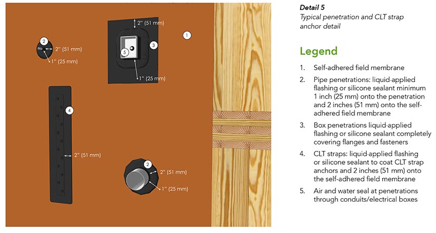
Penetrations are typically cut or cored through the CLT panel. It is best practice to pre-plan locations to mitigate any conflicts with other physical building components or with the construction sequencing.
Base-of-Wall Detailing
A typical CLT base-of-wall condition is depicted in Detail 6.
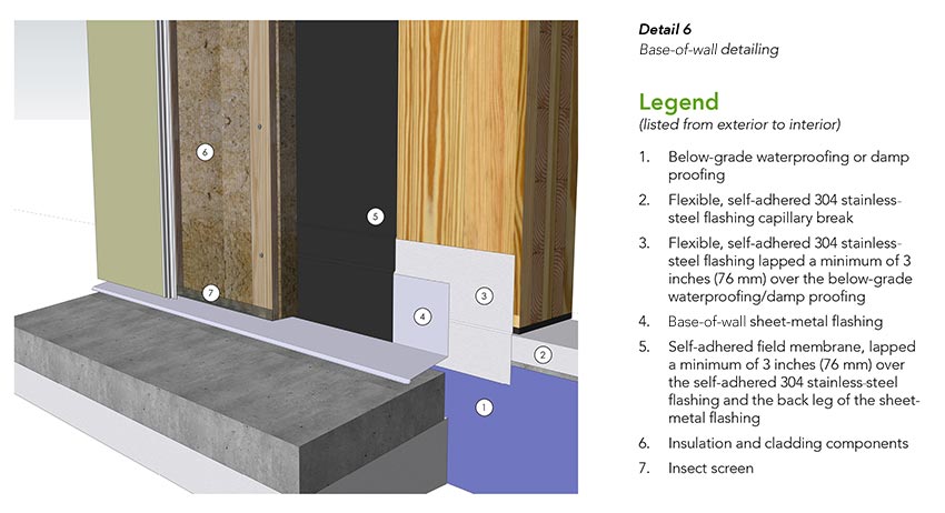
CLT is not used in below-grade applications, and local building codes dictate the minimum required clearance between the finish ground elevation and structural wood components that are supported by exterior foundation walls and footings. Typically, this requirement is 6–8 inches or the wood is required to be preservative treated. But regardles, 8 inches of clearance is best practice for CLT wall panels at exterior foundation walls and footings.
Best practice also dictates that the CLT is separated from the foundation using a vapor-impermeable membrane to provide a capillary break and barrier against burrowing insects. In Detail 6, this membrane is provided by the flashing. The sheet-metal flashing at the base of the CLT deflects drained moisture out of the assembly and away from the below-grade assembly. While the insect screen at the bottom of the cladding opening helps to prevent pests from burrowing into the assembly cavity, additional protective measures may be required in termite-prone areas.
CLT Roof Design and Best Practices
Roof structures can be classified by their pitch, and the approach to water and moisture management at roof assemblies typically varies based on roof pitch. Strategies for the design of exterior insulated CLT roof enclosures sloped at a pitch of 2:12 or greater, as shown in Figure 3-5, and at less than 2:12 are discussed separately. It should be noted that CLT roofs insulated from the interior are atypical in cold climates and require careful consideration of the air- and vapor-permeance properties.
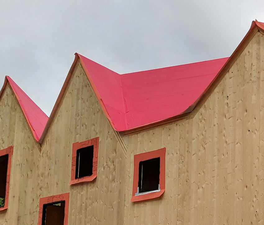
Figure 3-5
A vapor-permeable AB roof underlayment is installed over a gabled CLT roof at Haus Gables in Atlanta, designed by Jennifer Bonner.
CLT Roof Design for ≥ 2:12 Pitch
Details 7 and 8 illustrate two CLT roof assembly options with a 2:12 or greater slope. These assemblies use a UV stable AB roof underlayment at two key locations:
As a roof underlayment beneath the finish roof material. At this location, the membrane sheds water that may bypass the finish roof material and also protects components below from moisture.
Over the top of the CLT. At this location, the membrane serves as the AB and also minimizes the risk that the CLT panel is exposed to moisture should a failure in the assembly components above occur. This membrane layer also serves as a temporary roof membrane to protect the CLT structure from construction-phase moisture until the remaining assembly materials are installed.
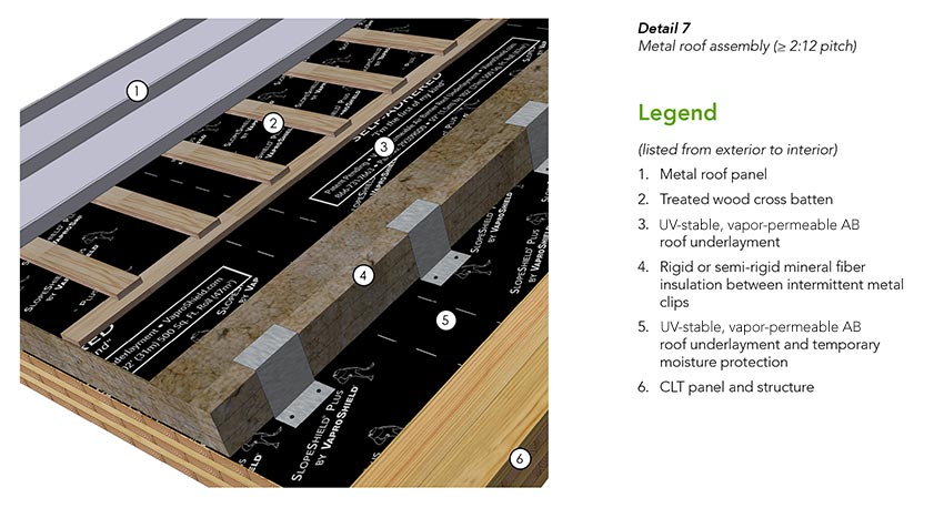
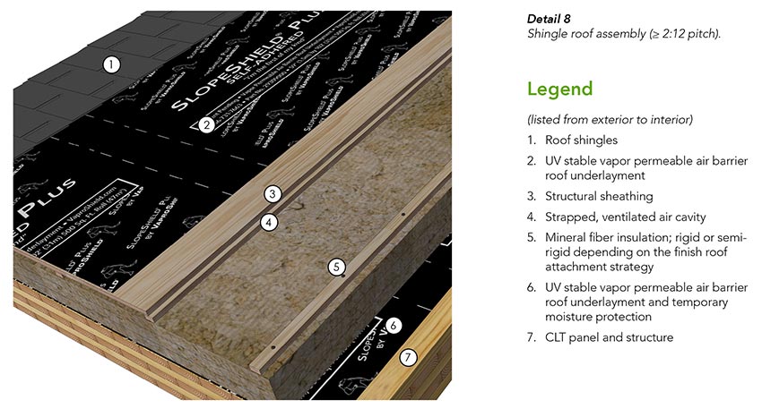
In both assemblies, vapor control is provided by the CLT panel. Unlike most common roof underlayment products, the AB should be vapor permeable to allow for some drying of the CLT substrate after application. It also offers extended UV stability and can be left exposed for up to six months prior to cover to provide greater flexibility in the construction schedule as compared to less UV-stable underlayment products. It is also important to consider that some finish roof materials, such as metal panels, may require a high-temperature underlayment membrane. The vapor-permeable AB can be used in high-temperature roofing applications with acceptable service temperatures up to 225 degrees Fahrenheit.
Depending on project-specific requirements, the assembly shown in Detail 7 can be made more durable by fully adhering the top layer of underlayment to a solid sheathing layer such as plywood, similar to what’s shown in Detail 8. Another drainage matrix may also be added above the roof underlayment where a ventilated and drained cavity is required by the finish roof manufacturer if the finish roof is not attached using a batten system or similar standoff.
The remaining assembly layers in Detail 7 and Detail 8 include:
- Layers of mineral-fiber insulation, as required to meet the targeted thermal performance of the roof assembly. Rigid mineral wool insulation is required when long screws are used for the direct attachment of the nail base sheathing to the CLT, and semi-rigid insulation may be used when the attachment is through a system of clips or similar methods.
- A strapped and ventilated air cavity to further encourage drying below the finish roof materials.
- Finish roof materials (e.g., metal panels, slate tiles, asphalt shingles, etc.) attached to a plywood substrate or treated wood cross battens.
Roof-Penetration Detailing
A typical penetration detail for a CLT roof assembly sloped at 2:12 or greater is shown in Detail 9. Similar to wall penetrations, the placement of roof penetrations requires planning to prevent construction conflicts. Penetrations through the roof underlayment are flashed for continuity of the WRB, AB, and/or temporary moisture protection layer.
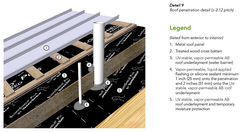
Fastener penetrations at structural clips and similar penetrations used for the attachment of the finish roof and sub framing may also need to be considered. At slopes less than 4:12, vapor-permeable liquid-applied flashing or neoprene shims must be provided under metal clips and similar penetrations to improve the sealing around fasteners. Additional treatment at clips for roof slopes of 4:12 or greater are not required.
Rake and Eave Detailing
A typical CLT roof assembly rake and eave detail is shown in Detail 10. Here, the vapor-permeable AB laps over the CLT panel edge to protect the wood end-grain. Liquid-applied flashing extends from the wall membrane to the underside of the CLT roof panel to provide an AB transition at the roof-to-wall interface.
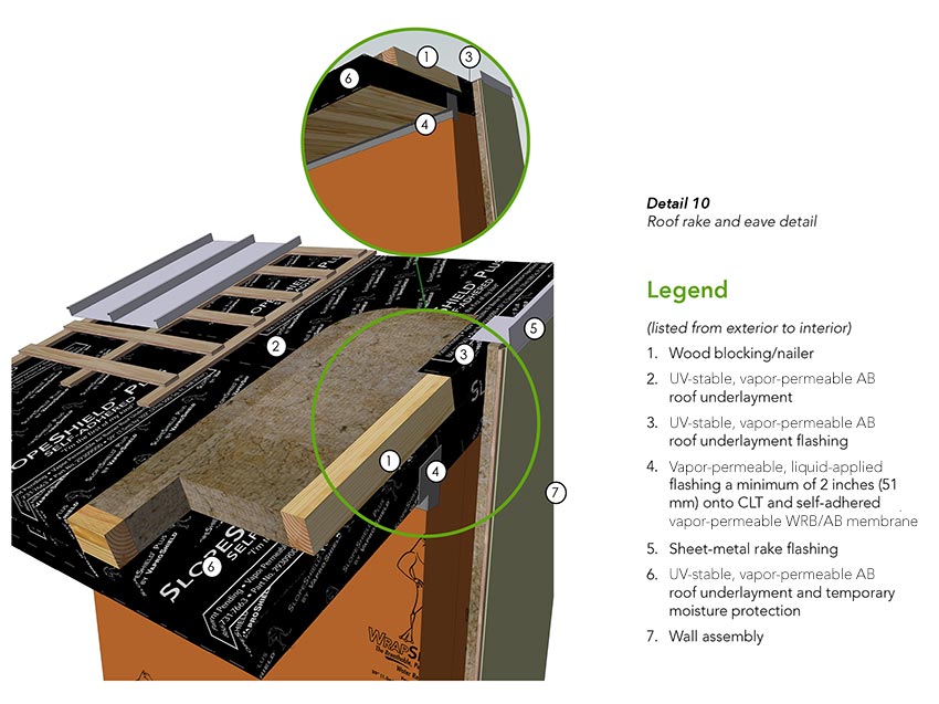
The roof-rake flashing is shown stripped into the roof underlayment to ensure that all water shedding is directed downslope toward the eave. Typically, the drainage strategy will include a gutter system at the eave to collect and drain the water runoff.
CLT Roof Design at < 2:12 Pitch
Typical components of a conventional roof assembly with a slope less than 2:12 are shown in Detail 11. In this assembly, the roof membrane is intended to act as a perfect barrier against water ingress, and the roof underlayment serves as a temporary roof membrane to protect the CLT panels during the construction phase.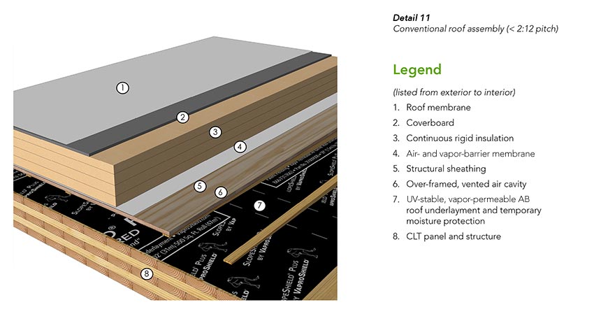
An un-sloped CLT roof panel is unable to readily shed water, so it is particularly sensitive to wetting during construction. To provide temporary moisture protection until the remaining roof assembly layers are installed, the vapor-permeable AB membrane is applied over the un-sloped CLT roof panel. With water-resistive properties, it can facilitate some panel drying while still protecting the underlying panel from bulk water when laps, penetrations, and terminations are appropriately detailed and when a means for draining the roof area of standing water is provided.
Best practice is to slope the roof membrane to the roof’s drainage and overflow system with roof drains or scuppers. Sloped over-framing provides the slope in the roof assembly shown in Detail 11. It also creates an air gap that can be used for observations to facilitate locating roof leaks, should they occur, or to provide a ventilated cavity to the interior to encourage panel drying, if required, at any stage during construction or occupancy. The vent space and over-framing provides the added benefit of helping to avoid damage to the CLT panel during future reroofing activities. The ventilation gap should not be vented to the outdoors once in service. It should be noted that local fire-safety requirements, however, may not allow a clear ventilation gap in this assembly.
Alternatively, slope may be provided by the roof insulation or the CLT panel/structure itself, as shown in Figure 3-6. In all cases, the air- and vapor-barrier membrane is provided below the insulation to prevent air leakage and vapor diffusion into the roof assembly.
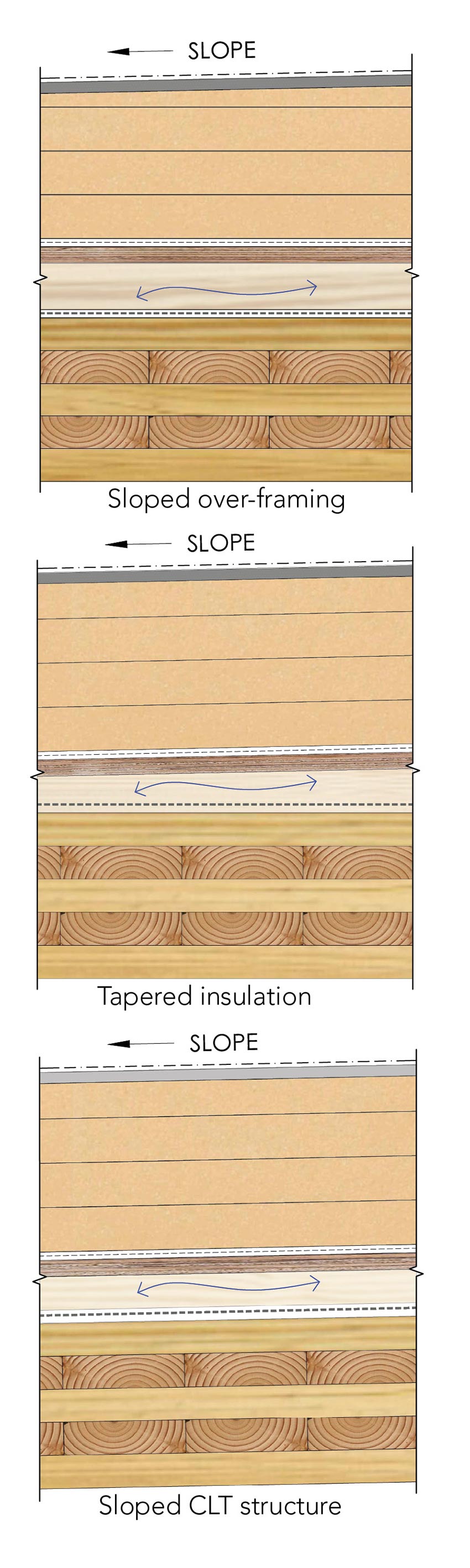
Figure 3-6
Roof-Parapet Detailing

A roof-to-parapet transition is shown in Detail 12.
When using a roof underlayment as a temporary moisture-protection membrane over the CLT roof panel, the perimeter is sealed at the parapet to close off this joint to water ingress. This seal can be accomplished with a strip of vapor-permeable liquid-applied flashing.
The parapet blocking and coping slopes to the roof side of the parapet. Flashing provides the primary moisture protection for the top of the CLT wall panel. Flashing is rated for service temperatures up to 200 degrees Fahrenheit, so it can be used in most high-temperature coping applications.
Construction-Phase Considerations
The design process and construction-phase planning are often heavily intertwined in successful mass timber projects. Inappropriate moisture management of CLT during construction and building service can lead to dimensional changes, microbial growth, or general deterioration of the CLT panels and other enclosure components, according to the Canadian-based forest sector research and development firm FPInnovations’ CLT Handbook.
Therefore, it is important that a moisture management plan is developed to outline steps taken during all phases of construction to minimize CLT moisture exposure.
Building codes typically require the moisture content of wood to be less than 16–19 percent prior to cover. However, many of these guidelines were developed with lightweight wood-framed construction in mind and do not consider the hygric mass of mass timber elements. Thus, it is typically advisable to limit the moisture content of CLT wall, floor, and roof panels to the lower end of this range—approximately 16 percent at all locations—prior to cover.
If CLT is wetted to above the maximum moisture levels during construction, drying of the CLT panel can take a substantial amount of time and lead to costly construction delays. Drying can be enhanced with a combination of heat and ventilation. However, drying of an already wetted panel does not eliminate the risks for permanent damage and panel distortions caused by fluctuating moisture content and rapid dimensional changes, particularly if the drying rate is too high.
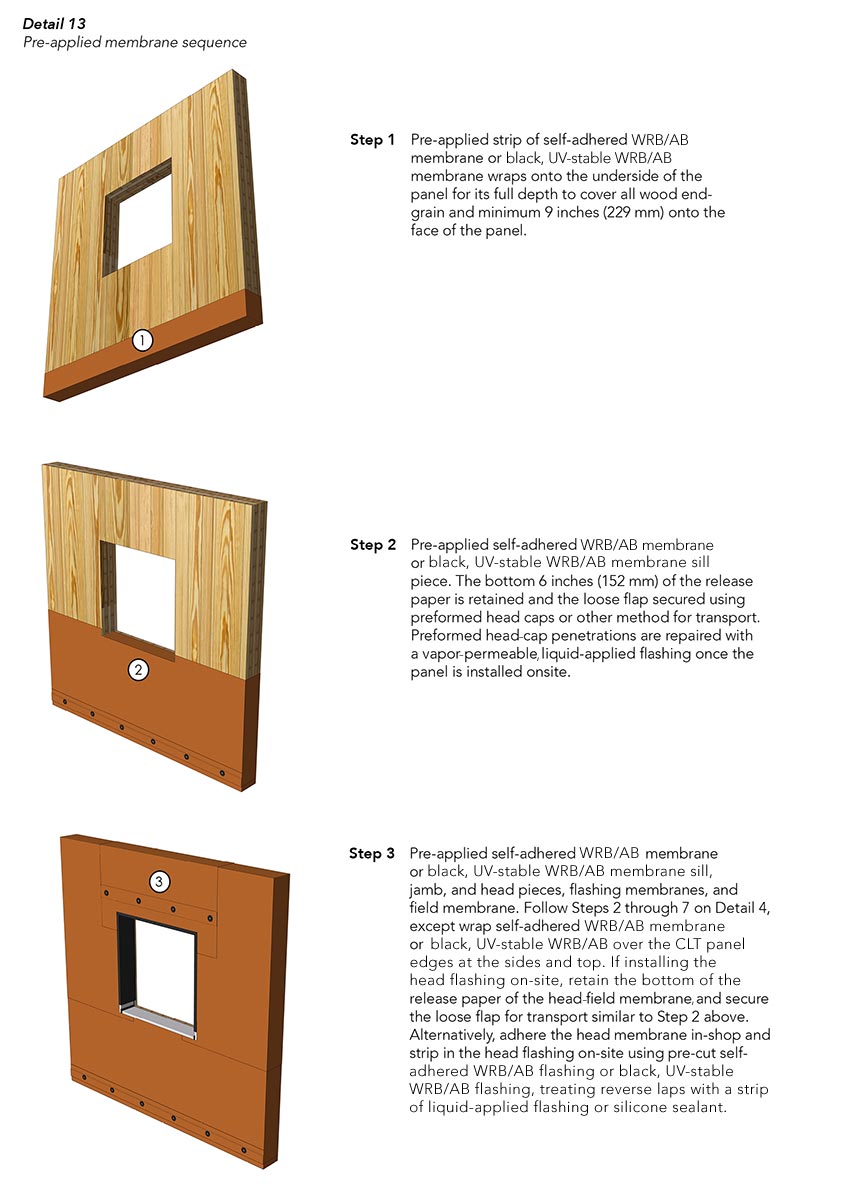
Construction tenting can help eliminate moisture-related risks during construction, but some projects do not have the means to provide this protection. As an alternative, one step to reduce the potential moisture exposure is to take advantage of the pre-application of water-resistive membranes off-site. Pre-applying a CLT panel with a water-resistive membrane offers the benefit of protection during shipping and staging on-site and can reduce the building dry-in period. These membranes also remain part of the building’s final enclosure design. Thus, an additional membrane application or the removal of temporary membranes is often not necessary.
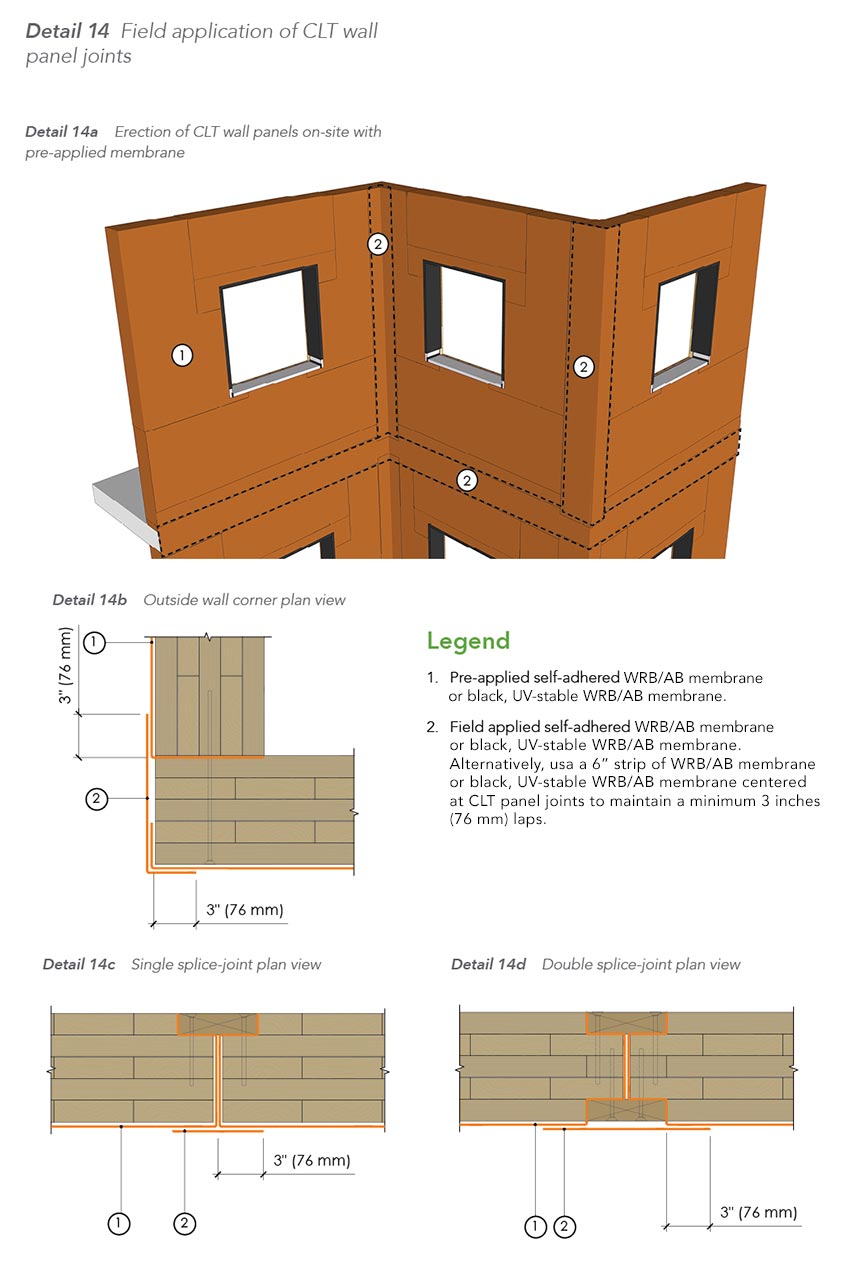
Once the CLT panels are erected on-site, the exposed faces and edges of the CLT panel, including joints, rough openings, and penetrations need to be treated. A sequence specific to preinstalling a self-adhered WRB/AB over CLT wall panels is shown on Detail 13. Once erected in the field, recommended detailing for panel joints at wall areas is shown in Detail 14a and for roof areas in Detail 14b.
In horizontal roof and floor applications, the CLT panel will be laid horizontal, or near horizontal, to form the roof or floor deck, increasing the CLT’s moisture exposure as compared to wall or sloped-roof applications. Thus, extra precautions and planning may be required. A roof underlayment may be used as a temporary protection membrane over un-sloped or low-sloped CLT in most instances, as shown in Detail 11. Note that ponded water may begin to slowly pass through the membrane to wet the CLT over time. However, this technology has been tested to demonstrate that 24 inches (210 mm) of standing water over the membrane will not result in water leakage over a 24-hour period. This tested water depth exceeds what would be reasonably expected in the field. At the same time, it should be noted that this test is performed in the middle of the sheet membrane. Laps, penetrations, and terminations are at the highest risk for moisture intrusion, so they require appropriate detailing and effective moisture management practices during the construction phase to minimize wetting risks.
While the properties of the roof underlayment offers many benefits for the moisture management of CLT by permitting outward drying, it may not be appropriate for use as a temporary roof protection membrane in regions with a high risk for wood decay due to this same property. The Nail-Laminated Timber Design & Construction Guide classifies regions as high risk for wood decay when the local Scheffer Climate Index exceeds 70. Within the scope of this guide, put out by the Binational Softwood Lumber Council, high-risk regions include some coastal areas of the north Pacific and some Appalachian regions. A more appropriate option for moisture protection in these regions may be a factory-applied, fully adhered, vapor-impermeable waterproof membrane if installation is expected to occur during wet seasons. If this strategy is followed, it is especially important that a durable membrane is used and that all membrane laps are fully sealed prior to water exposure because any moisture that bypasses the protective membrane will be very difficult to dry without removal of the vapor-impermeable membrane.
Additional methods and measures that may be included in the moisture-management plan are:
- Water-repellent coatings: Factory-applied, this coating can help limit the CLT’s moisture uptake. Ideally, the coating is moderately vapor permeable to maintain the drying potential of the CLT. Pre-applied coatings can be particularly valuable at panel edges where moisture uptake through the wood end-grain is quicker. Water-repellent coatings may not be appropriate, as the sole form of protection in the higher-risk regions for wood decay since these coatings are not 100 percent effective if exposed to moisture for prolonged periods, as stated in RDHBuilding Science’s “CLT Floor Moisture Testing Report: UBC Brock Commons Tall Wood Student Residence.” It should also be noted that water-repellent coatings do not address potential gaps between CLT laminations or water ingress at CLT panel joints, which can otherwise be bridged by sheet membrane products. Water-repellent coatings should also not be relied upon to provide in-service water control, and thus a separate water-resistive membrane will still be required for CLT enclosures.
- Shipping coordination and protection: By coordinating shipping with the construction schedule, just-in-time delivery principles can be used to limit the period of time that CLT panels will be staged on-site, therefore reducing CLT exposure to on-site sources of moisture. Pre-installation of membranes during panel fabrication can provide some protection of the panels during shipping. However, additional protection may be required depending on the season, climate, and distance of the fabrication facility from the job site.
- Site protection: CLT panels may need to be stored on-site prior to being erected onto the building. Site protection may be necessary to reduce the panel’s exposure to moisture, depending on the season and climate. Where membrane products are pre-installed prior to delivery, moisture protection during storage may be minimized.
- General water management: Moisture uptake occurs over time, and thus short-term exposure periods may be tolerated provided that conditions for drying exist after the wetting event, according to the Nail-Laminated Timber: U.S. Design & Construction Guide. General procedures for limiting the bulk-water exposure time during erection and prior to final cover are imperative for managing the wetting risk. This should include plans to clear ponding water from horizontal CLT areas, including snow and ice, in a timely manner. Pre-applying membranes and treating penetrations and joints once the panels are erected can also be used to reduce the exposure. However, as previously mentioned, removal of ponded water over vapor-permeable membranes should still be a priority during construction.
While an effective use of these strategies can reduce the risk for introducing construction moisture into CLT, the in-service moisture performance of the enclosure can still significantly impact the CLT structure. For this reason, it is important to follow the previously delineated guidelines to ensure that the CLT assembly is able to effectively manage in-service water and vapor loads.
Summary
Mass timber and CLT construction offers many advantages, including enhanced modularity, reduced construction schedules, improved thermal performance, and material sustainability.
However, mass timber’s propensity to absorb moisture from the environment and the relative vapor impermeability of CLT panels introduces unique challenges when incorporated with the building enclosure. These challenges should be considered during design and construction phases to ensure long-term performance.
Highly vapor-permeable WRB/AB membranes can be used to effectively manage water and air in CLT wall and roof assemblies and allow outward drying of the CLT while in service. Additionally, they offer enhanced fire and UV performance.
Foresight and planning are required during the construction phase to effectively manage CLT exposure to construction moisture and to minimize risks of in-service enclosure performance issues or construction delays. Pre-applying membranes to the CLT off-site can play an integral role in the construction-phase water-management strategy in addition to potentially reducing the construction schedule. More general water management strategies should also be in place to provide additional protection and prevent prolonged periods of ponded water depending on the climate and season.