Moisture Management in Wall Assemblies: Air, Water, and Vapor Barriers
Selecting the appropriate protective barrier based on climate, codes, and design criteria
![]() Continuing Education
Continuing Education
Use the following learning objectives to focus your study while reading this month’s Continuing Education article.
Learning Objectives - After reading this article, you will be able to:
- Identify moisture management strategies for buildings.
- Analyze design criteria for air, water, and vapor barriers.
- Determine the impact of climate, heating, and cooling cycles on selection and location of protective barriers within wall assemblies.
- Discuss code requirements for air, water, and vapor barriers.
- Design wall assemblies using protective barriers.
Regardless of project location or building type, the goal of a successful building design is to keep water out and provide thermal control within the interior spaces. Understanding the basics of moisture control and the role of air, water, and vapor barriers in design of wall assembly systems is important in order to avert potential problems that can arise from air and water infiltration.
The building envelope, or building enclosure, separates indoor and outdoor environments. A building enclosure controls heat flow, airflow, water vapor flow, rain, groundwater, light and solar radiation, noise and vibrations, contaminants, environmental hazards, odors, insects, and fire.
When moisture infiltrates the building envelope, several undesirable conditions can occur, including mold and mildew, structural steel corrosion, and rotting wood. These conditions can result in high energy costs, ongoing maintenance problems, compromised indoor air quality, and failure of one or more architectural and engineering building systems. If they are not adequately addressed, the problems caused by moisture infiltration can potentially increase risk and liability concerns for architects, design professionals, building owners, and building occupants.
Moisture is the general term used for water in its different physical states, and includes solid (ice), liquid (water), and gas (water vapor). For all practical purposes, moisture moves through the building enclosure as liquid water and as water vapor. Moisture problems are generally the result of liquid water accumulation, which could be from liquid water infiltration or condensation of excess water vapor transported by air currents or by vapor diffusion. Condensation of excess water vapor occurs on surfaces with temperatures below the dew point temperature, which is the onset of condensation.
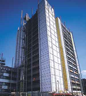 |
| Uncontrolled air leakage occurs from higher to lower pressure and could transport significant amounts of water vapor. Photograph © 2006 David S. Allee |
Some moisture problems cannot be avoided. Proper design can help reduce risk and make a building more tolerant to moisture. This article will describe moisture control strategies, and the use of protective barriers, including water-resistant barriers, air barriers, and vapor barriers. Requirements related to the position of each barrier in the building envelope for moisture management and condensation control will also be addressed.
Bulk Water Transport Through The Bulding Enclosure
Rain is the main water source for above grade walls. Rain can penetrate behind cladding and into the building enclosure through any openings, cracks and gaps in the assembly, and accumulate inside the wall cavity. The main mechanisms for bulk water intrusion include gravity, capillary action, kinetic energy of rain driven droplets, and pressure differential.
There are two basic approaches for rain penetration control: control the driving forces across the openings or eliminate the openings. The first approach includes proper sloping to the outside (gravity drainage to outside), capillary break (to control capillary action), shielding the openings (to control rain penetration due to kinetic energy), and pressure equalized rain screen walls (to control pressure differential across the envelope).
Water intrusion mechanisms through above grade wall assemblies |
 1. Gravity: can draw water down through opening and cracks 2. Capillary Action: sucks water through small cracks & pores 3. Rain Droplets: falling rain can pass through openings 4. Pressure Differential: can push or suck water through cracks |
The second approach consists of eliminating the openings. This can be achieved through a face-seal design, which is difficult to achieve, due to sealants exposure and extensive maintenance requirements, or by using a secondary line of defense, such as a water-resistant barrier.
Water-Resistant Barriers
Water-Resistant Barriers are materials specifically designed to protect against rain penetration and prevent water leakage into the building interior. Water-resistant barriers, also referred to as the drainage plane, are typically installed behind cladding for the two main types of wall assemblies, cavity insulation and exterior insulation.
In wall assemblies with insulation inside stud cavity, the water-resistant barrier is typically installed on the exterior face of the exterior sheathing. In exterior insulation walls, the water-resistant barrier can be either sandwiched between the exterior sheathing and the exterior rigid insulation(1), or outside of the exterior rigid insulation(2). The former is the most common installation, while the latter should be used for insulation materials that are sensitive to water.
Typical position within the building envelope for water-resistant barriers |
 |
Codes and Performance Requirements
The 2006 International Building Code (IBC) requires that water-resistant barriers be used and installed to provide a continuous drainage plane and drainage pathways to the outside of the building envelope, including weep holes and through-wall flashing. The following excerpts apply:
Section 1403.2. Weather protection: The exterior wall envelope shall be designed and constructed so as to prevent the accumulation of water within the wall assembly by providing a water-resistive barrier behind the exterior veneer, as described in Section 1404.2, and a means for draining water that enters the assembly to the exterior.
Section 1404.2. Water-resistive barrier:A minimum of one layer of No. 15 asphalt felt, complying with American Society for Standards and Materials (ASTM) D226 for Type 1 felt or other approved materials, shall be attached to the studs or sheathing, with flashing as described in Section 1405.3, so as to provide a continuous water-resistive barrier behind the exterior wall veneer.
Section 1405.3 Flashing: Flashing shall be installed in such a manner so as to prevent moisture from entering the wall or to redirect it to the exterior.
Materials Requirements
The minimum requirement for water-resistant barriers is for the material to withstand a fixed hydrostatic pressure of 55 centimeters (cm) for five hours without leaking, as per the American Association of Textile Chemists and Colorists test, known as AATCC-127 or the Hydrostatic Head test. This standard is based on a No. 15 asphalt felt and is the minimum requirement. There are many water-resistant barriers that meet and exceed this requirement, such as fluid applied membranes, self-adhering membranes, and many non-perforated building wraps. Perforated wraps have virtually no hydro-head and do not qualify as water-resistant barriers.
Water Vapor Transport Through The Building Enclosure
Water vapor can be transported into the building enclosure in two different ways, via air transported moisture and vapor diffusion.
Air transported moisture is the main source of water vapor in the building enclosure. Air leakage occurs through porous materials and unintentional openings in building assemblies, such as cracks and channels, due to the difference in total air pressure across the assembly. The air flows from higher to lower pressure and it could transport significant amounts of water vapor into the building enclosure. The amount of water vapor contained in the air depends on temperature and relative humidity, with warm air being able to hold more moisture than cold air. Even though air leakage has consequences beyond moisture transport, including energy efficiency, indoor air quality (IAQ), and comfort, the air transported moisture is one of the most damaging consequences of uncontrolled airflow.
Air Barriers
Materials that resist airflow are called air barriers. Many building materials can resist airflow and therefore could function as air barrier components. However, for effective envelope airtightness, these materials must be joined together into airtight assemblies, which are further joined into a continuous air barrier system for an airtight building enclosure. Air barrier membranes are materials designed to resist air infiltration and provide a more practical way to achieve continuity. A continuous air barrier controls airflow, hence the moisture migration through air currents as well as other undesirable consequences of unplanned airflow.
The location of air barriers within the building envelope is not important from the standpoint of controlling air leakage, as it can be located anywhere in the wall assembly. However, the location is very important for durability and constructability. For durability, it is preferable to have the air barrier behind the exterior cladding, to protect it from direct weather exposure. For constructability, it is preferable to have the air barrier outward of the structural frame, for maintaining continuity at penetrations associated with structural elements. Air barriers are ideally located towards the exterior of the building envelope, because it is easier to achieve and maintain continuity.
The installation requirements for air barriers are similar to those four water-resistant barriers. In wall assemblies with insulation inside stud cavity, the air barrier is typically installed on the exterior face of the exterior sheathing. In exterior insulation walls, the air barrier can be either sandwiched between the exterior sheathing and the exterior rigid insulation or outside of the exterior rigid insulation. The former installation is most common; the latter should be used when thermal insulation performance can be affected by wind-washing. According to the Building Science Corporation, wind-washing is the phenomenon of air movement that occurs due to wind entering building enclosures, typically at the outside corners and roof eaves of buildings. Wind-washing can have significant impact on thermal and moisture movement, and hence thermal and moisture performance of exterior wall assemblies.
The location of both air and water-resistant barriers in the wall assembly depends on continuity, durability, and maintainability. A single membrane could perform as an air and water barrier, if proper materials are chosen. An air barrier membrane is often water-resistant; however, not all materials that meet the minimum requirement for water resistance, such as asphalt impregnated felts, and papers, are effective air barriers. Other materials, such as perforated wraps, are not effective as water or air barriers
Air Barrier Codes and Performance Requirements
Four main performance requirements for air barrier materials and systems include air infiltration resistance, continuity, structural integrity, and durability.
These criteria are described in Chapter 26 of the American Society of Heating, Refrigeration and Air-Conditioning Engineers (ASHRAE) Fundamentals Handbook and summarized by the Air Barrier Association of America atwww.airbarrier.org.
Air Barrier Materials
There is no national standard for acceptable air infiltration rates of air barrier materials in the U.S. The National Building Code of Canada, which has required air barriers since 1995, specifies that air infiltration rates of air barrier materials must not exceed 0.004 cfm/sq. ft. (cubic feet per minute per square ft.) at 0.30 inch water pressure differential. This standard was adopted by Massachusetts in 2001, and is proposed for adoption by Minnesota in 2007.
Examples of materials that qualify as air barriers include self-adhered membranes, fluid applied membranes, non-perforated building wraps, and closed cell polyurethane foams. Examples of building materials which do not qualify as air barriers include asphalt impregnated papers and felts, perforated housewraps, expanded polystyrene (EPS), plain and asphalt impregnated fiberboard, uncoated concrete block, batt and semi-rigid fibrous insulation, and cellulose spray-on insulation.
Air Barrier Assemblies
The standard specification, ASTM E1677, requires that air infiltration rates for air barrier assemblies must not exceed 0.06 cfm/sq. ft. at 0.30 inch water pressure differential. These assembly requirements were adopted by the Wisconsin energy code in 2003. ASTM E 2357 is a new test method which was approved in 2006 and can be used as an alternative test method for air barrier assemblies
Whole Building Airtightness
There are no accepted criteria for what constitutes an airtight building. A study by the National Institute of Standards and Technology (NIST) entitled, "Investigation of the Impact of Commercial Building Envelope Airtightness on HVAC Energy Use," summarizes envelope airtightness of 166 buildings, 144 in North America and 22 in the U.K. The air leakage rates measured by various standard methods and normalized by area of the above-ground portion of the building envelope were found to vary over a broad range, from less than 0.5 to 2.7 cfm/sq. ft. at 0.30 inch water. No trends towards increased airtightness in more recent buildings were found.
The impact of building envelope airtightness on building performance is generally recognized. However, while existing codes require sealing of the building enclosure, there is no quantifiable measure for an acceptable air-tightness of the opaque building envelope, unlike windows, which require some measure of airtightness for compliance.
An excerpt from the International Code Council (ICC) requirements for building envelope sealing is as follows:
502.4.3 Sealing of the building envelope. Openings and penetrations in the building envelope shall be sealed with caulking materials or closed with gasketing systems compatible with the construction materials and location. Joints and seams shall be sealed in the same manner or taped or covered with a moisture vapor-permeable wrapping material.
It should be noted that the code specifies the use of a moisture vapor-permeable wrapping material, as opposed to a vapor non-permeable material, or vapor barrier, which could interfere with condensation control strategies.
The code description on the sealing of the building envelope provides no guidelines on the recommended airtightness, and has been compared to requiring that care be taken when installing insulation without specifying a minimum R-value. Some states and code organizations have adopted compliance criteria for airtightness of materials or assemblies airtightness, including the National Building Code of Canada (NBCC) (1995), Massachusetts (2001), Wisconsin (2003), and Minnesota (2007). In 2006, ASHRAE approved an amendment to the ASHRAE 90.1 model energy code that would require air barriers for most commercial buildings, and provide three quantifiable compliance options: air barrier materials, not to exceed 0.004 cfm/sq. ft. at 0.30 inch water; air barrier assemblies, not to exceed 0.04 cfm/sq. ft. at 0.30 inch water; and whole building, not to exceed 0.4 cfm/sq. ft. at 0.30 inch water.
Vapor diffusion is the second water vapor transport mechanism through the building enclosure, in addition to air-transported moisture. Vapor diffusion is the movement of water vapor molecules through vapor permeable materials, from regions of higher vapor pressure to lower vapor pressure, or higher vapor concentration to lower vapor concentration.
The rate of water vapor diffusion depends on vapor pressure difference, or concentration difference, across the material or assembly, as well as the water vapor permeance, which is expressed in perms. Based on water vapor permeability, materials are classified as vapor permeable or vapor non-permeable.
Water vapor diffusion is the transport of water vapor molecules through vapor permeable materials |
 |
Vapor permeable materials allow vapor diffusion. Vapor permeability can vary over a wide range. The higher the perm rating, the more permeable the materials. According to the 2006 International Building Code (IBC), materials must have a minimum of five perms to be considered vapor permeable.
Vapor non-permeable materials do not allow vapor diffusion. These materials are called vapor barriers or vapor retarders. According to the 2006 IBC, materials with vapor permeability of 1.0 perm or less are vapor barriers.
Vapor Barriers
Vapor diffusion is another source of moisture for the building enclosure, and a vapor barrier (or vapor retarder) is sometimes used to control diffusion and potential condensation. However, the amount of water vapor transported through vapor diffusion is significantly lower than the amount transported by air currents. It is estimated that less than 2% of all water vapor movement through the building enclosure is due to diffusion, while over 98% is due to air transported moisture. Consequently, in order to avoid conditions which could lead to interstitial condensation it is critical to firstly protect against air leakage (using air barriers), and protect against vapor diffusion when appropriate. The installation requirements for air barriers and vapor barriers are quite different, and using a single membrane to perform both functions (e.g. air and vapor barrier) could lead to condensation problems if not properly understood. For example, while the location of air barriers within the building envelope is not important from the standpoint of controlling air leakage, and the air barrier can be located anywhere in the wall assembly, the vapor barrier location is critical for condensation control, and it is climate specific.
Typical vapor barrier location in the wall assembly |
|
Heating Climates Vapor barrier inside |
Cooling Climates Vapor barrier outside |
 |
|
The vapor barrier must be located on the side of the building envelope with higher vapor pressure in order to prevent diffusion into the envelope, known as diffusion wetting, and not interfere with diffusion of incidental moisture out of the envelope, or diffusion drying. As a general rule, for walls with insulation inside the stud cavity, the vapor retarder should be located toward the inside in climates dominated by heating, and toward the outside in cooling dominated climates.
While these general rules are useful guidelines, it is still appropriate to conduct a condensation analysis for specific climates, building envelope systems, and intended building use. Many U.S. climates have both heating and cooling cycles, and simple rules may not apply. In such cases, the vapor barrier may end up on the wrong side during one of the two cycles.
The vapor barrier codes were first introduced in Canada, with predominantly heating climates, where vapor barriers were installed on the interior (warm) side of the wall. The IBC then adopted similar requirements across all U.S. climate zones, without a proper understanding of the impact of vapor barriers in different climates. As a greater understanding of different climate needs and the consequences of the impact of vapor barriers on diffusion drying was reached, the code was changed. The 2006 IBC no longer has prescriptive requirements for vapor barrier use in mixed climate zones 1, 2, 3, and 4, which cover southern and coastal zones of the U.S.
US Climate zone map
The 2006 International Building Code does not mandate vapor barrier use in climate zones 1, 2, 3, and 4 (below the black line) |
 |
Climate Issues
The reason climate is important when considering diffusion drying is because the climate determines the exterior temperature and relative humidity. This determines the exterior vapor pressure, hence the vapor pressure difference between the exterior and the interior conditioned space, therefore the diffusion direction. The climate determines how buildings dry, whether towards the inside or towards the outside, depending upon the sign of the vapor pressure difference, whether positive or negative.
Diffusion direction: from higher to lower water vapor concentration (or higher to lower vapor pressure) and it is climate specific
|
 |
Material Choices
The choice of materials is critical for providing a diffusion open pathway in order to promote diffusion drying. As a general rule, condensation control requires that the building envelope materials increase in permeance in the direction of vapor diffusion. This means that in predominantly heating climates, where diffusion is typically from the inside to the outside, the wall assembly must have vapor permeable materials towards the outside. In cooling climates, where diffusion is typically from the outside to the inside, the wall assembly must have vapor permeable materials towards the inside. In mixed climates, proper moisture management requires diffusion open pathways in both directions, to the inside during summer and to the outside during winter.
|

Moisture Management Principles And The Choice Of Barriers
Moisture problems occur if buildings get wet and stay wet, because they are unable to dry. According to building scientist Joe Lstiburek, Ph.D., P.E., "moisture problems are fundamentally rate issues: moisture accumulation occurs if the wetting rate exceeds the drying rate." Consequently, moisture management must include strategies to manage the balance between wetting and drying, that is, to prevent wetting and promote drying.
The balance of wetting and drying, main sources
and mechanisms |
 |
The main moisture sources, bulk water, air transport, and diffusion, do not have an equal contribution to wetting. In order of their contributions, these sources are bulk or rain water infiltration, which is usually the largest moisture source for above-grade walls; air transported moisture, which could contribute up to 200 times more moisture than water vapor diffusion; and water vapor diffusion, which has the smallest contribution to wetting, when compared to the other two sources.
In order to prevent wetting, it is essential to protect against the main moisture sources, bulk water (with a water-resistant barrier) and water vapor transported by air currents (with an air barrier). In addition, it is recommended to protect against moisture transported by diffusion (with a vapor barrier), as long as the use of a vapor barrier does not interfere with the wall drying ability.
The potential drying mechanisms in buildings include drainage of incidental water to the outside, controlled ventilation (not to be confused with uncontrolled air leakage through the building envelope), and vapor diffusion.
For example, a continuous drainage plane is an effective strategy for removing incidental bulk water, and a ventilated air space behind the cladding can reduce the moisture content in the air space outside the sheathing and facilitate drying. However, in order for ventilation drying to be effective, it is still necessary for water vapor to be able to diffuse from the envelope into the ventilated space. Given the importance of vapor diffusion as a drying mechanism, it is critical that a diffusion pathway is considered.
Wall design is important because the arrangement of building envelope elements influences the conditions within the wall, and therefore the environment under which the materials must function.
For walls with insulation inside the stud cavity, the main temperature gradient occurs across the interior wall cavity, over the thermal insulation. As a result, in heating climates, temperatures towards the exterior of the insulated cavity could drop below the dew point temperature creating conditions that could lead to interstitial condensation. In a cooling climate, the cooler surfaces would be towards the inside. In order to avoid persistent wetting, the wall must have diffusion open pathways, to allow diffusion drying. This wall design relies on diffusion drying for incidental moisture management.
For the exterior rigid insulation wall design, the main temperature gradient occurs across the exterior insulation, outside the interior wall cavity. As a result, the dew point temperature is moved outside the wall cavity, reducing the potential for condensation. This wall design is more robust and less sensitive to condensation, and does not rely on vapor diffusion for drying.
In order to choose the appropriate barriers for building projects, the following guidelines apply:
Water-Resistant Barriers are critical for most climates to prevent bulk water intrusion. They are typically installed behind the cladding, towards the exterior side of the building envelope. If the water-resistant barrier is vapor permeable, it will not interfere with the condensation control strategies.
Air Barriers are critical for most climates to prevent heating and cooling energy loss, as well as prevent moisture transported by air currents. The location of an air barrier within the building envelope is not important from the standpoint of controlling air leakage, because an air barrier can be located anywhere in the wall assembly. Air barriers are located towards the exterior of the building envelope for ease of constructability and continuity. If the air barrier is vapor permeable it will not interfere with the condensation control strategies. A single membrane is generally used to perform both air barrier and water barrier functions.
Vapor Barriers should only be used in those climates where diffusion into the wall cavity occurs predominantly in one direction. The vapor barrier should be located on the high vapor pressure side of the envelope. In climates dominated by heating, this means that the vapor barrier should be located toward the inside, and in cooling climates toward the outside.
A single membrane can perform all three functions, and serve as an air, water, and vapor barrier. When a membrane is intended to be used as a vapor barrier, in addition to an air and water barrier, it must be determined if the typical location of air and water barrier, such as on the exterior of the building envelope, also meets the condensation control criteria for a vapor barrier, that is, if the vapor barrier is on the high vapor pressure side of the building envelope.
Every time that a vapor non-permeable membrane (such as vapor non-permeable peel and stick or fluid applied membrane) is used with insulated stud cavity wall design, conditions for condensation are created in most North American climates. In predominantly heating climates, a vapor non-permeable air and water barrier installed on the exterior side of the building envelope (the preferred installation for air and water barriers) creates conditions for condensation all year round. In U.S. climates with both heating and cooling seasons, this creates conditions for condensation during the heating season. Section 502.4.3 of the ICC, Sealing of the Building Envelope, requires a moisture vapor-permeable wrapping material, in order to avoid potential condensation. The requirements and properties of vapor barriers must not be confused with those of air and water barriers.
Factors to consider when selecting barriers for projects include the following:
1. Water and air barriers are critical for controlling the most important moisture sources in buildings and should be used in most climates. As long as these membranes are vapor permeable, their typical location, at the exterior of the building enclosure, and under the cladding, will not interfere with the condensation control strategies.
2. Diffusion is essential for drying, and a diffusion pathway must be allowed. The preferred diffusion direction is climate specific. Many U.S. climates require diffusion pathways in both directions, toward the inside and toward the outside.
3. Vapor barriers should only be used in climates where they do not interfere with diffusion drying, such as predominant heating or cooling climates. In many U.S. climates, the vapor barrier would be located on the wrong side of the wall assembly during the heating or cooling season.
4. If an air and water barrier is also a vapor barrier, its location in the building envelope is determined by the vapor barrier function and must follow the vapor barrier requirements for condensation control. In many U.S. climates (except for predominantly heating or cooling climates) such membranes should be avoided. Air and water barriers should be vapor permeable.