Introducing the Steel-Plate Composite Core
Eliminating the need for formwork and reinforcing bars, a new coupled steel-plate composite wall system, appropriate for wind and seismic zones, is expected to shave months off of mid-rise and high-rise projects
![]() Continuing Education
Continuing Education
Use the following learning objectives to focus your study while reading this month’s Continuing Education article.
Learning Objectives - After reading this article, you will be able to:
- Evaluate different types of steel and concrete composite core systems used to support elevator shafts, exit stairs, restrooms, and mechanical/electrical services.
- Describe the concrete-filled composite plate shear wall (CF-CPSW) system and its main durability, constructability, and performance benefits.
- Explore CF-CPSW’s first application for Seattle’s Rainier Square, including performance requirements in a high-seismic, high-wind environment.
- Assess how and why experts anticipate that CF-CPSW will become a serious consideration for high-rise building designs.
While structural engineers, contractors, and structural steel manufacturers are consistently coming up with better, more efficient ways of designing and building nonresidential structural systems, a new approach to hybrid core construction seems to be garnering even more attention and promise than usual.
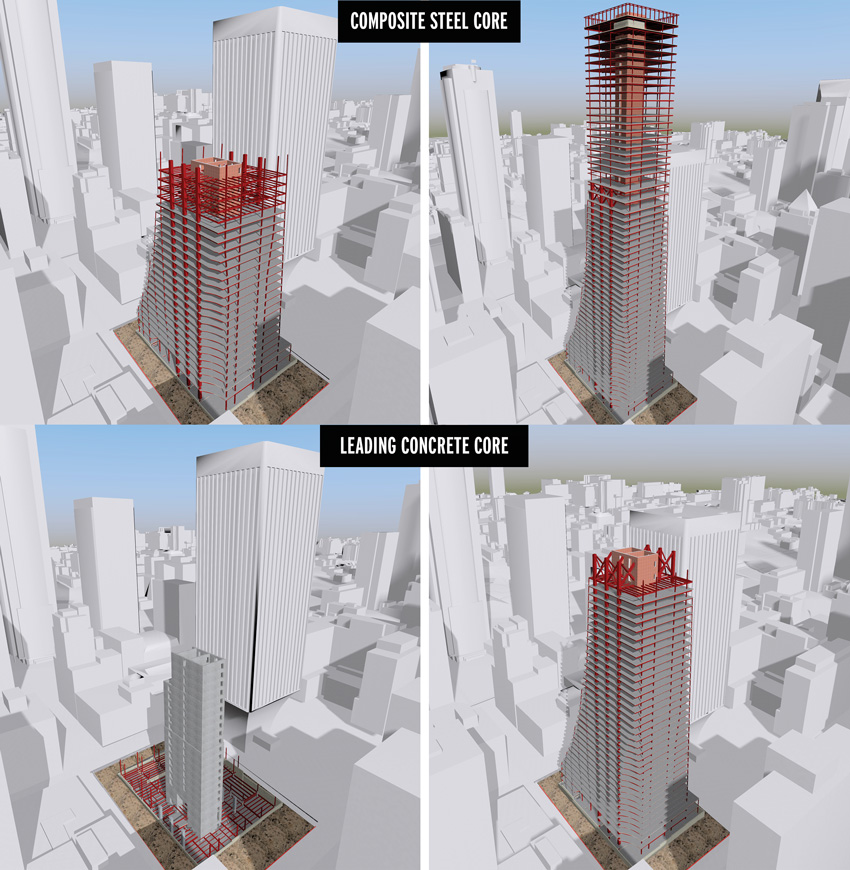
Image courtesy of MKA
As compared to conventional concrete core construction, which takes three to five days to erect a floor, a new high-rise core innovation, the coupled steel-plate composite wall system, can be erected at the rate of one floor per day.
In fact, in his 30-some years in the industry, expert Michel Bruneau, Ph.D., P.Eng., professor, Department of Civil, Structural and Environmental Engineering, University of Buffalo, New York, states, “I have never seen the industry so excited about a new type of structural system.”
In place of a traditional concrete core, Ron Klemencic, P.E., S.E., Hon. AIA, chairman and CEO, Magnusson Klemencic Associates, Seattle, has adapted the steel plate composite system currently utilized by the nuclear power industry. In Klemencic’s version, a high-strength concrete shear wall is sandwiched by two structural steel plates, which serve as both the formwork and reinforcing bars. In addition to lending a high level of seismic support, the coupled steel-plate composite wall system is much faster to erect. As opposed to a concrete core, which takes three to five days per floor to construct, the steel can be erected at the rate of one floor per day.
Consequently, the higher the structure, the more construction efficiencies to be gained, which is why the high-rise market is looking very carefully at the first coupled steel-plate composite wall system currently under construction at the MKA structurally designed Rainier Square Tower in Seattle. It is anticipated that this coupled steel plate shear wall system will actually shave several months off the construction schedule and 2 percent off the construction costs to build the 58-story high-rise.
Beginnings
To appreciate the evolution of this newer composite system, a little history is in order.
Prior to 9/11, much high-rise steel construction, particularly in New York City, used a braced steel core. However, the World Trade Center collapse—where the steel core yielded to the impact of the terrorist-flown aircraft, cutting off exit routes—led the mid-rise and high-rise building market to exclusively start using reinforced concrete construction.
While the impact would have pulverized concrete cores as well, this addressed what was envisioned as public concern. Consequently, for the past two and half decades, with some notable exceptions such as Renzo Piano’s New York Times Building, most tower construction has consisted of reinforced concrete core walls surrounded by structural steel composite floor framing.
The construction of these cores was accomplished using formwork and an internal densely packed reinforcing bar cage. But while reinforced concrete provides the required strength and stiffness, there is a long cycle time involved in setting the formwork, installing the reinforcing steel, placing the embedded plates, installing the sleeves and block-outs, and placing the cured concrete before the next level of the core can be constructed.
Another drawback to the concrete core systems are that they require extensive internal reinforcing. If any penetrations through the wall are required for items such as piping, they may interfere with this reinforcing, and the location of the reinforcing may interfere with the placement of the embedded steel plates required for the attachment of steel floor framing beams.
As a result, the need to reduce construction time and resolve interferences have been major incentives to develop alternative structural core solutions.
Hybrid Core Alternatives
Generally speaking, hybrid core alternatives use the same concrete shear walls but with different types of coupling beams. Coupling beams are structural components designed to connect individual shear walls where openings are required in the shear wall. By connecting the shear walls, the coupling beams stiffen the building and may serve as a fuse to dissipate seismic movement. This could be concrete walls and steel coupling beams, concrete walls and coupling beams made from engineered cementitious composites, or concrete walls and precast post-tensioned coupling beams, explains Amit H. Varma, professor, Lyles School of Civil Engineering, and director, Bowen Laboratory of Large-Scale CE Research at Purdue University, West Lafayette, Indiana.
“In general, all these systems attempt to improve the seismic performance of the core wall system by improving the performance of the coupling beams,” explains Varma. “The hybrid cores replace these conventional beams with other alternatives to alleviate rebar congestion and constructability issues while providing good energy dissipation capacity.”
While these alternate systems are being used in practice, their use is not widespread. Varma conjectures that because their economic advantages are limited to the coupling beams, the cost benefits are therefore not very significant.
Another composite innovation is called Bi-Steel. The lightweight tied-plate steel panels are assembled on-site, erected, and then filled with concrete. This system can be constructed six times faster than conventional concrete, is highly flexible, and offers efficiencies with build sequences and reduced site congestion. In addition, no formwork is required, and the system offers better accuracy in interfacing with the adjoining steelwork.
The original Bi-Steel system included a patented welding procedure to affix interconnecting tie rods between two steel plates. While it has been used for a few apartment buildings in London, the system does have some fabrication limitations, and is not designed for seismic locations so its application has been limited.
Another alternative, called the modular core, is a prefabricated precast concrete modular unit. The columns, beams, and walls are precast concrete; prestressed hollow core flooring and steel units provide the structural hybrid frame solution; and in-situ concrete is used to facilitate structural connections. The system has been used in the United Kingdom.
In yet another configuration, steel plate shear walls, a thin steel web plate is welded or attached to horizontal and vertical boundary elements. As a thinner component, the walls can be thinner as well, thereby offering more usable square footage. Similarly, the building weight and required structural support, particularly when compared to concrete walls, is significantly less.
The relatively thin steel plate also offers excellent post-buckling capacity, is faster to construct, and is designed to handle wind and seismic loads. Most notably, the structural system was designed for the U.S. Federal Courthouse in Seattle, the Hyatt Regency Hotel at Reunion in Dallas, the Century in San Francisco, and a few projects in Japan.
Demonstrating the cost savings offered by the steel plate shear wall (SPSW) system, a study performed for The Century project recorded an average wall thickness, with furring, of 18 inches, as compared to an average concrete shear wall thickness of 28 inches, resulting in a savings of 2 percent in gross square footage.
The Century project study also found that the building weighed approximately 18 percent less than a building designed using a concrete shear wall core system. This led to a reduction of foundation loads due to gravity and overall building seismic loads. In terms of the project schedule, a one-month reduction in time was attributed to the SPSW system.
Because SPSW systems are usually more flexible than concrete shear walls, primarily due to their flexural properties, when designed for tall buildings, additional flexural stiffness must be provided. For example, for The Century and U.S. Federal Courthouse projects, large composite concrete infill steel pipe columns were used at all corners of the core wall to improve both the system’s flexural stiffness and overturning capacity.
There is also the consideration that excessive initial compressive force in the steel plate panel may delay the development of the tension-field action, so it’s important that the construction sequence be designed to avoid excessive compression in the panel. For the Courthouse, this was addressed by delaying the welding of the plate splice connections until most of the dead load deformation occurred in order to relieve the precompression within the SPSW panel.
Concrete-Filled, Composite Plate Shear Wall System
While these systems do offer advantages, it’s the above-mentioned newer application of the coupled-filled steel, composite plate shear wall (CF-CPSW) system for high-rise structures that is really turning heads.
Similar to how a reinforced concrete shear wall system functions, with a similar wall arrangement and thicknesses, with this newer system, the reinforcement is provided by the steel plates on the outside of the wall.
“The steel plate composite wall system is a natural evolution of the reinforced concrete wall system,” explains Varma.
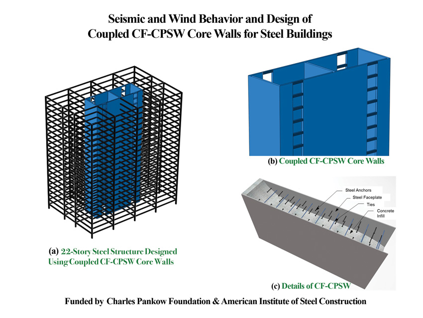
Image courtesy of AISC
The coupled steel-plate composite wall system is a high-strength concrete shear wall sandwiched by two structural steel plates.
Looking at issues related to steel rebar congestion and concrete placement at the base of thick concrete walls in high-rise buildings, plus the time and effort needed for formwork placement, concrete casting, formwork removal, etc., the steel-plate composite wall system was a next step in structural evolution to address these concerns.”
As noted, the concept is currently used by U.S. nuclear structures and for missile and aircraft impact resistance. Similarly, the United Kingdom utilizes it for blast-resistant construction and Japan applies it for its nuclear structures as well.
Involved in creating standards for this system, the AISC funded a research project in 2011, which led to AISC N690-12s1, 2015, Specification for Safety-Related Steel Structures for Nuclear Facilities, and Design Guide 32: Design of Modular Steel-Plate Composite Walls for Safety-Related Nuclear Facilities.
Construction of the system involves crosstying two ½-inch-thick steel plates together with rods at 1 foot on center, both vertically and horizontally. Fabricated in the shop, the steel plate modules are then shipped to the job site and erected simultaneously with the structural steel framing.
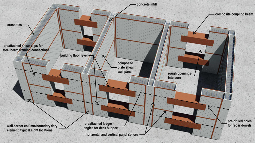
Image courtesy of MKA
This cross section of the CF-CPSW design shows the composite plate shear wall panel, concrete infill, composite beams, and other details.
When the erection of two tiers (four floors) of the structural frame is complete, including installation of the steel plate modules, self-consolidating concrete fills the voids between the plates, bonding with the rods and plate to form a composite wall system. Thus, erection of the steel framing is a continuous operation with no internal reinforcing of the plates required.
Noted Benefits
Because the steel framing doesn’t have to wait for the concrete core, this significantly increases the speed of construction.
In fact, an MKA construction study of the Rainier Square project found that a concrete core building would take 474 working days to top out, as compared to just 377 working days for the hybrid wall building.
“The 97 working day difference equals 136 calendar days, which means the owner will benefit from four-and-a-half months lower contractor’s overhead and general conditions costs, four-and-a-half months lower financing costs, and four-and-a-half months of earlier rental income,” Klemencic explained in a presentation at Purdue University, where he recently received a distinguished engineering alumni award.
Another difference with the CF-CPSW system is that the rebar is positioned outside the wall. Furthermore, the formwork doesn’t have to be removed and instead functions as a part of the structural system.
In terms of structural performance, the system can achieve high reinforcement ratios without congestion and concrete placement issues.
“The structural stiffness, strength and deformation capacity of the composite systems are comparable or better than those of equivalent reinforced concrete systems,” states Varma. “The system leverages the advantages of both steel and concrete construction materials, where the concrete infill delays the local buckling of the steel plates and the steel modules confine the concrete infill to improve its ductility. Additionally, if needed, the system has the ability to provide excellent blast and impact resistance due to its dual steel plate armored design.”
Adding some more details, he relates that two or more steel-plate composite walls—which can be planar, C-shaped, or I-shaped in cross-section—are connected together by coupling beams at each story level.
“Under seismic loading, the coupling beams undergo inelastic deformations first and dissipate energy,” Varma explains. “Eventually, the base of the composite walls also undergo inelastic deformations and dissipate more energy.”
Furthermore, the coupling beams, which are rectangular steel box sections filled with concrete, enable the coupled core wall structures to resist lateral loads from wind or earthquakes by allowing the composite walls and coupling beams to bend together as a unit, he adds.
“Walls with steel plates have an enormous shear resistance,” Bruneau explains. “Concrete is nice in compression, but weak in tension and doesn’t perform well in earthquake situations. Because the steel is continuous, this ensures the continuing of the resistance of the shear forces.”
Yet another advantage is the fact that steel tolerances, per AISC standards, are tighter than the concrete tolerances set by the American Concrete Institute. With other hybrid systems, the steel framing beams connecting to the concrete core must be fabricated last because they can only be field measured for final dimensions after the concrete core walls poured, explains Lawrence F. Kruth, P.E., vice president of engineering and research, American Institute of Steel Construction, Chicago.
With the CF-CPSW system, steel connects to steel with no need for embedded plates, thereby eliminating tolerance issues and the challenge of overlapping trade issues. “The tolerance difference between the concrete cores and steel framing creates challenges in design, detailing, and construction that can be avoided with the sandwich walls,” confirms James O. Malley, S.E., group director and senior principal, Degenkolb Engineers, San Francisco.
The CF-CPSW is also considered to be a modular system, as the steel modules are manufactured in a shop and then shipped to site for assembly and concrete casting. “Prefabricated in the shop in accordance with specified tolerances, this reduces fit-up issues during erection between the steel framework and embed plates attached to the composite cores,” explains Varma. “This leads to better coordination between the steel fabricator, erector, and general contractor for the project.”
This continuity of construction is also advantageous for high-rise projects where outrigger systems are required for wind comfort as the steel outriggers easily connect to the steel plates, Malley adds.
All Eyes on Rainier
Considered a “proof of concept,” many structural engineers are watching Rainier Square as it prepares to rise up to its 850-foot apex as the world’s first high-rise CF-CPSW system.
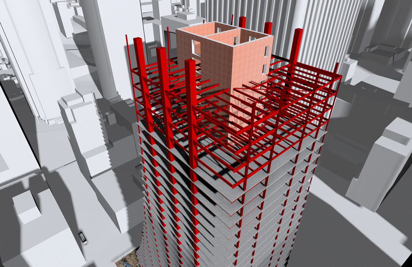
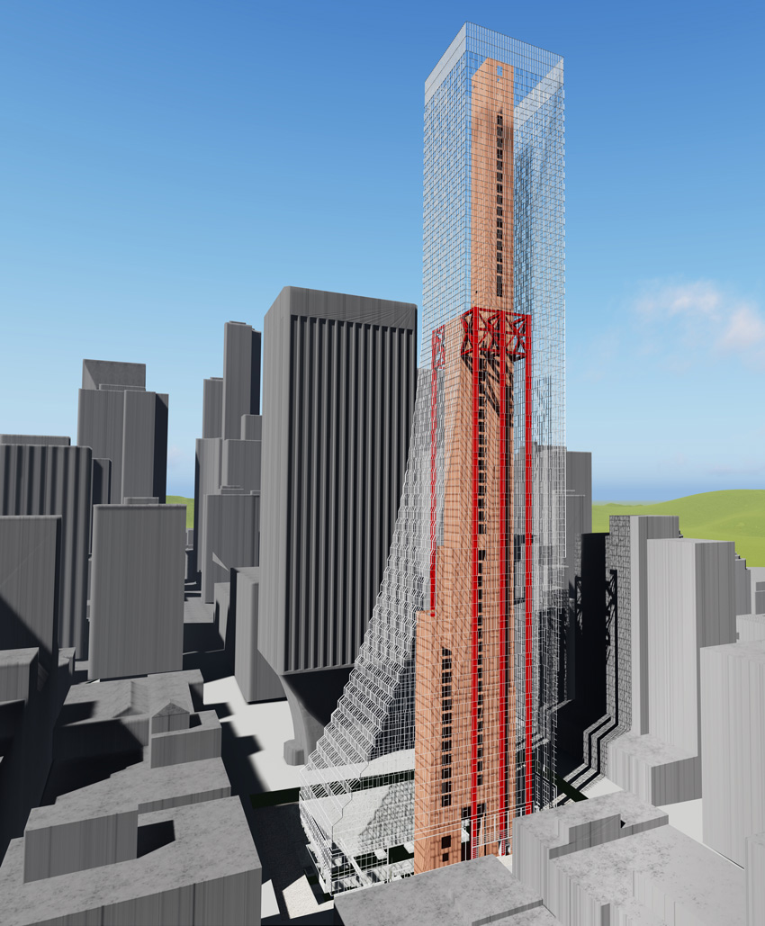
Image courtesy of MKA
This Revit model displays the concrete-filled composite plate shear wall core system.
“Rainier Square is a very significant step forward for this system,” confirms Malley. “Having such a signature project will undoubtedly provide impetus for other projects to consider this as an alternative to a fully concrete core.”
Fortunately for MKA, the environment was ripe for such an innovation. For starters, the building owner, Wright Runstad, has a history of advancing design and construction through the adoption of new technology.
Klemencic says that Wright Runstad was the first U.S. developer to consider performance-based seismic design for a high-rise building. In fact, PBD was used for the Bellevue, Wash., Three Bellevue Center and is now the standard of the industry.
Furthermore, the City of Seattle tends to be more open than some U.S. cities when it comes to allowing newer approaches to building.
“Our openness to innovation provides an environment in Seattle that encourages and supports alternative designs, while our peer-review process provides a means for us to feel confident in the building’s expected performance,” says Cheryl Burwell, P.E., S.E., engineering and technical codes manager, City of Seattle.
Ultimately, the CF-CPSW system is expected to decrease project construction time by 20 to 40 percent and reduce general condition costs, overhead costs, and financing costs, reports Kruth. “Also, by completing the structure sooner, the owner will receive rental income months earlier than projected,” he says. “On this project, this could result in tens of millions of dollars in savings.”
The Details
Delving into the details of the project’s design and construction, the super-structure will be erected in sequence, thereby avoiding the time restriction imposed by coordinating with a traditional concrete core construction.
In a Rainier Square Development white paper on the project, penned by Klemencic and Varma along with Klemencic’s MKA colleague Brian Morgen, Ph.,D., P.E., S.E., the engineers describe the system as prefabricated wall panels and boundary elements comprised of steel face plates, typically ½ inch thick, separated by 1-inch-diameter cross-connecting tie rods spaced 12 inches on center, both horizontally and vertically, with an overall wall assembly thickness varying from 21 to 45 inches.
Wall panels, on average, measure 13 feet 9 inches tall by 37 feet long, are being prefabricated off-site and will be shipped in stacked groups.
The wall panels, along with integrally detailed concrete-filled coupling beams, will be erected at the same pace as typical steel erection. The prefabricated wall panels are designed with enough strength and stability to support up to four floors of steel floor beams and metal decking before being filled with concrete. Furthermore, the face plates will serve as permanent formwork for the infill concrete.
Klemencic, Varma, and Morgen also note that the cross-connecting tie rods will be critical to the overall performance of the system as they serve multiple purposes, including:
- Strength and stability of the unconcreted wall panel to support erection loads;
- Lateral resistance and face-plate bracing during the concrete infill operation;
- Mechanical connectivity between the steel plates and in-fill concrete for composite action, leading to enhanced axial and shear strength;
- Confining pressure for the concrete for superior seismic performance under ultimate demands;
- Delamination of the steel plate and concrete infill is prevented;
- Out-of-plane shear strength; and
- Slenderness of the steel plates is reduced.
Once the walls are erected and the panel-to-panel connections are made, concrete will be piped into the space between the two plates with a self-consolidating concrete mix.
“The concrete combined with the steel plates provides the ultimate strength and stiffness for the core wall assembly as a composite section,” they explain.
Fabrication and Construction Challenges
In order to create the prefabricated units, approximately 500 panels and 200 boundary elements are being prefabricated. As part of this process, the fabrication sequence and connection of the tie rods are critical to the panels’ efficient and timely fabrication.
Similarly, panel-to-panel connections during the site erection sequence are also a critical detail of the system, something that is particularly key for a high-seismic zone like Seattle. Addressing this issue, welded connections are being exclusively used in order to ease field fit-up and speed construction. Furthermore, Klemencic, Varma, and Morgen explain that project-specific, prequalified welds have been developed and are being tested to add to the efficiency of the connections.
In terms of the penetrations that must be made through the composite steel plate, Klemencic points out that this process is inherently easier than reinforced concrete because unlike the former, the rebar is visible. That said, MKA encouraged the project team to coordinate all of the MEP openings early enough in the process so that they could be included in the shop fabrication in order. This will ultimately save the costs of adding them in the field.
Set to commence later this summer, the team anticipates that erection will take a year. Putting this into perspective, erecting the entire building should take less time than casting just the concrete core of a conventional concrete structure.
“The final assembly will be spray fire-proofed in order to satisfy the jurisdictional requirements for a 3-hour assembly,” they report.
At the same time, the CF-CPSW is being studied to better understand the fire performance of the system to determine if minimizing or eliminating the need for supplemental fire protection for some portions of the system might be possible.
In terms of the floor plate, there will be seven levels of underground parking, and retail and offices until level 37. The next three floors will house mechanical, elevator transfer, and amenity levels, and the upper 18 floors will house 200 residential units.
A few floors up, the south face slopes inward, with a more pronounced slope designed for the east side. Starting at 140 feet by 245 feet, the footprint gradually shrinks to 120 feet by 120 feet once it ascends to the 40th floor.
Interestingly, the original Rainier Square design called for a concrete core, but the mid-height embedded outrigger trusses required to stabilize the tall, thin building would have been more costly and time consuming.
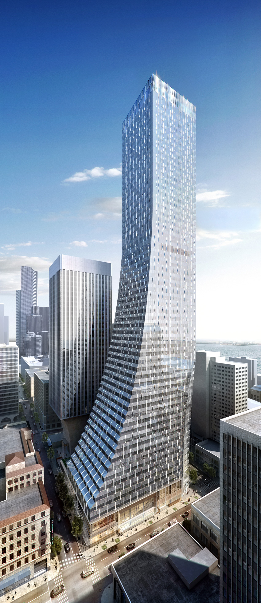
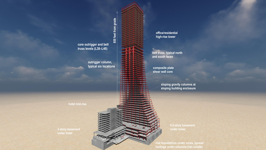
Image courtesy of MKA
As the first high-rise project to incorporate the CF-CPSW system, the 58-story Rainer Square Tower in Seattle is expected to shave several months off the construction schedule and 2 percent off the construction costs.
It was at this point that Wright Runstad challenged the design team to come up with a lower-cost structural solution and a faster time line. Klemencic, who had already developed the CF-CPSW system, saw this as an opportune time to suggest the system, and the structural design was soon altered to incorporate the system.
Of course, as a high-rise subject to high wind, the CF-CPSW still required stiffening, so three lines of 40-foot-deep outrigger trusses with buckling-restrained braces (BRBs) from floor 38 to floor 40 were designed to span from the core to steel perimeter box columns with crossties. These ties will confine the box columns’ cast concrete infill and lend stability during construction.
According to Klemencic, the BRBs will absorb quake energy like fuses by going through their yield cycle, providing the required support and capping the load to the outrigger columns. “The CF-CPSW interfaces more readily with the outrigger trusses as all of the connections are steel to steel as opposed to steel to concrete,” he explains. “This greatly simplified the connection detailing, fabrication, and erection.”
The outrigger columns are interconnected by east-to-west perimeter trusses, which provide a redundant load path. A 12-foot-thick mat, measuring 180 feet by 128 feet, will support the outrigger columns, most of the wide-flange perimeter columns, and the 870-foot-tall core, with a maximum footprint at the base of 93 feet by 40 feet. Gravity-only columns at the base, outside the mat, will bear on spread footings.
Because the system is so new, it has yet to be codified and therefore required a performance-based seismic design approach. While the City of Seattle welcomed the CF-CPSW system, it did so with the caveat that it be reviewed by three structural peer reviews, including two practitioners and one academic.
Because the system has never been built, the team felt it was prudent to build two mockups, according to Klemencic. “One to test concrete placement methods, mix designs, and consolidation, and a second to test steel shipping, handling, erection, fit-up, and connectivity,” he says.
Images courtesy of MKA
For seismic protection, MKA designed three lines of 40-ft-deep outrigger trusses with buckling-restrained braces (BRBs) for Rainier Square’s floors 38 to floor 40.
More specifically, the first mockup helped to determine the number and location of access ports for the hoses and to evaluate different baffle-hole layouts in the boundary elements, and measure and monitor the concrete temperature.
Relevant Research
Starting back in 2006, Purdue University studied a nonproprietary version of the Bi-Steel concept with funding from the Charles Pankow Foundation.
“Several aspects of the system were modeled numerically and physically tested, including the stability of the assembly prior to concrete placement forces in the cross-connecting tie rods and a 3/8-scale, 5½-story, T-shaped wall assembly under cyclic loading,” explain Klemencic, Varma, and Morgen.
With the research gathered, detailed design guidelines called “Design Procedure for Dual-Plate Composite Shear Walls” were then created.
While this research is helpful, further testing was needed in order to optimally apply the system to commercial applications, being that nuclear structures have long, squat walls dominated by shear, as compared to high-rise applications, which have tall, slender walls, explains Varma.
Currently, collaborative research is being performed at Purdue University, under Varma’s direction, and Bruneau is heading up another study at the University of Buffalo.
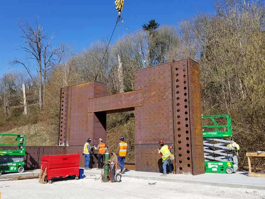
Photo courtesy of MKA
This mockup for Rainiar Square confirmed erection procedures, fit-up, and welding production rates.
Funded by the Charles Pankow Foundation and AISC, and supported with in-kind material donations and expertise from Supreme Group and MKA, the goal is to optimize the CF-CPSW system by reducing the number of crossties and replacing them with shear studs. The research will also inform the next version of AISC’s “Seismic Provisions for Structural Steel Buildings.” Furthermore, AISC and the Charles Pankow Foundation are funding a FEMA P695 study at both universities.
At Purdue, the research keys in on investigating the performance of planar wall panels subject to varying axial loads, considering alternate crosstie arrangement and spacings, with the aim of making the overall system more efficient.
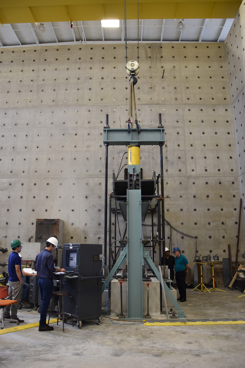
Photo courtesy of AISC
At Purdue University’s Bowen Laboratory, this composite wall test setup is being tested to combined axial load and cyclic lateral loading up to failure.
“The project focuses on the wind and seismic behavior and design of coupled steel plate composite core walls,” Varma explains. “It includes experimental evaluation of the lateral load behavior, including stiffness, strength, and deformation capacity of individual composite walls, including planar walls and C-shaped walls. It also includes experimental evaluation of the coupling beam-to-wall connections and the lateral load behavior of the coupled wall system.”
For the former, the actual assembly test parameters included were an axial load level of 10 to 30 percent of concrete axial load capacity and tie-rod spacing, achieving plate slenderness ratios of 24 to 48. The specimens were ½- to 3/8-scale models of the prototype walls designed for theme structures located in non-seismic and seismic regions.
Meanwhile, at the University of Buffalo, C-shaped and T-shaped wall panels will be tested to investigate the performance of the system with a shifting neutral-axial location, as well as corner detail performance.
The tests will apply 1 million pounds of force to simulate the way an earthquake bends a wall with lateral force. “We want to see how far we can go before we start losing capacity and damaging the wall. We hope to have a better understanding of seismic performance and to validate a number of details,” explains Bruneau. “We will then know how far we can push it.”
“This evaluation will focus on archetype structures—8-, 12-, 20- and 25-story buildings— and their seismic performance as evaluated by implementing the FEMA P695 procedure, adds Varma. The analytical results will be used to inform the seismic design performance factors for the system in the ASCE 7 Standard.
Once the Purdue research is completed in mid-2019, AISC plans to publish a design guide on the system to enable engineers to better understand the proper methods of designing the CF-CPSW system. The FEMA P695 study is planned for completion by the middle of the year and should ultimately yield a seismic response modification factor of R = 8, which is the highest of any shear wall system of any material, according to Kruth.
Currently, Composite Plate Shear Walls – Concrete Filled are addressed in AISC’s “Seismic Provisions for Structural Steel Buildings” and allowed by AISC’s “Specification for Structural Steel Buildings.” Consequently, once these AISC guidelines are adopted in IBC 2018, the CF-CPSW system should become more widely available for use, he adds.
Future Projections
With much at stake as the ground has been laid on Seattle’s Union Street between Fourth and Fifth avenues and erection is ready to begin, the building construction, if executed smoothly, will likely garner much attention as the speed advantage is significant. “Once a successful project is completed, there will be many interested parties,” Klemencic says.
Bruneau agrees that the new system could really change things up in the high-rise market, as it’s a completely different approach to core-wall construction. At the same time, he points out that the structural engineering industry is a conservative profession. “People are used to doing things a certain way, and it takes time to change that momentum,” he says.
Klemencic also acknowledges that owners and contractors tend to be reluctant to be the first to adopt new technology, but with a proven example, which hopefully Rainier will turn out to be, he predicts that the flood gates will open.
“There is significant interest in the coupled steel-plate composite wall system from engineers, fabricators, erectors, and general contractors alike,” relates Varma. “They are all looking at the system for its ability to leverage innovation, research, and design to solve real challenges related to high-rise building construction and economy.”
He adds that with the successful completion of a large-scale project such as the Rainier Square, this should build additional confidence in the industry. Furthermore, the publication of research-based, peer-reviewed design guidelines and recommendations for the system will add additional confidence.
“Moving forward, we believe future applications of this system will result from projects being identified as those that can benefit from the system’s performance and construction techniques, increased comfort in the design, and the willingness of local jurisdictions to entertain such proposals,” Burwell adds.
Summing up the significance of the project’s incorporation of this technology, in a recent Engineering News-Record feature, Klemencic said, “Rainier, Square brings together my insatiable search for ‘better,’ passion for research and development, and intense collaboration with the entire design and construction team to create a breakthrough in how tall buildings are constructed.”
In the same article, Shannon Testa, senior project manager, Lease Crutcher Lewis, the contractor on the project, predicted, “This is going to be a watershed in terms of high-rise construction.”
ENR quotes Malley as concluding, “Potentially, this system could be a game-changer and create unique opportunities beneficial to the marketplace.”

|
The Steel Institute of New York is a not-for-profit association created to advance the interests of the steel construction industry. The institute sponsors programs to help architects, engineers, developers, and construction managers in the New York building community develop engineering solutions using structural steel construction. www.siny.org |