Opportunities For Wood in Low-Rise Commercial Buildings
A versatile and economical approach to large openings, tall walls, and open floor plans
![]() Continuing Education
Continuing Education
Use the following learning objectives to focus your study while reading this month’s Continuing Education article.
Learning Objectives - After reading this article, you will be able to:
- Explain how wood-frame systems can be used to achieve design objectives commonly associated with commercial structures, such as tall walls, flat roofs, parapets, and open-front floor plans.
- Identify cost savings associated with Construction Types III and V compared to Types I and II, per the International Code Council’s Building Valuation Data.
- Discuss opportunities for achieving unlimited area for wood-frame commercial buildings under the International Building Code and implications of multi-tenant occupancies.
- Review applications of wood-frame construction in low-rise commercial buildings, with an emphasis on restaurant, retail, and office occupancies.
When designing restaurants, stores, and low-rise offices, certain features come to mind as typical. These buildings tend to have large openings that allow plenty of daylight. Many have high ceilings and (by extension) tall walls, open floor plans, and the ability to reconfigure the interior as tenant needs change. They often include irregular shapes, such as architectural features that make a chain restaurant instantly recognizable in a row of strip mall stores. Many also have flat roofs and parapets that hide rooftop mechanical units.
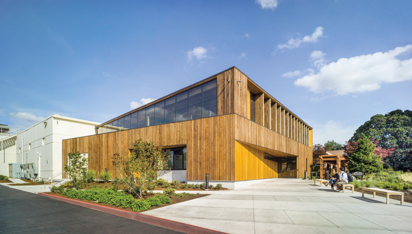
Photo: Eckert & Eckert
Diamond Foods Innovation Center
Location: Salem, Oregon
Architect: ZGF Architects
Engineer: KPFF Structural Engineers
Wood construction has the flexibility to meet all of these needs; wood can achieve the structural performance and quality objectives of even a large ‘big box’ store, cost-effectively, while providing a host of other advantages
This course is intended for building designers who want to learn more about the use of wood framing systems in low-rise commercial projects. For many, the motivation will be cost. As this course illustrates, wood structures can cost significantly less than comparable buildings made from other materials. Others are attracted to the idea of wood’s versatility, ease of use, and adaptability, while others still appreciate its renewability, sustainability, and light carbon footprint. Depending on the application, aesthetics and the growing body of research supporting wood’s biophilic qualities—i.e., the positive impact that exposed wood can have on a building’s occupants—may be the biggest driver for its use.
Intended to provide practical information that can be applied to projects, the course begins with code-related topics, including cost implications of construction type, opportunities for achieving unlimited area, and implications of multi-tenant occupancies. It provides an overview of wood wall and roof systems commonly used in commercial buildings, and highlights key design considerations. Examples of wood-frame buildings are highlighted, and a recent cost and environmental comparison of a big box store designed in wood versus steel is summarized. Code references refer to the 2015 International Building Code (IBC) unless otherwise noted.
YARD HOUSE BAR & GRILL


Photos: MBH Architects
Location: Chino Hills, California
Architect: MBH Architects
Engineer: Goodson Engineering
For this 6,500-square-foot restaurant, wood was used to span the dining room and create a cantilever over the outdoor patio. The trusses were left exposed, and redwood planking was used to cover the interior of the vaulted ceiling. Other wood products include dimension lumber stud framing for exterior walls, architectural grade Douglas-fir glulam beams, solid Douglas-fir posts (vertical truss posts), wood I-joists, plywood sheathing, cabinet-grade plywood (maple veneer), solid maple hardwood, and butcher block maple.
Construction Type and Cost
Under the IBC, most low-rise commercial buildings fall under one of the following occupancy groups:
- Assembly (Group A-2): Nightclubs, restaurants, taverns, bars
- Business (Group B): Banks, barber and beauty shops, dry cleaning and laundries, professional services
- Mercantile (Group M): Department stores, drug stores, markets, motor fuel-dispensing facilities, retail or wholesale stores, sales rooms
For these (and other) occupancy groups, structural wood framing is permitted in Construction Types IIIA, IIIB, IV, VA, and VB. The IBC specifies allowable height and area for each, and each has different requirements, largely related to fire protection. As shown in Figures 1–3, which highlight information from the International Code Council (ICC) Building Valuation Data, August 2015, the average cost for each construction type also varies widely.
Figure 2 highlights the difference in cost between two construction types commonly used for low-rise commercial buildings—Type IIA, which doesn’t allow structural wood framing, and Type IIIA, which is typically wood-frame. Both have similar allowable heights and building limitations, but the average Type IIIA building costs $16 to $22 per square foot less.
In Figure 3, Type IIB Construction is compared to Type VA—also commonly wood-frame—and shows an even larger savings of $24 or more per square foot for the wood building. Allowable heights and areas remain similar, with exceptions that include greater height for Type VA Assembly and Mercantile occupancies, and greater height for Type IIB Education and Business occupancies.
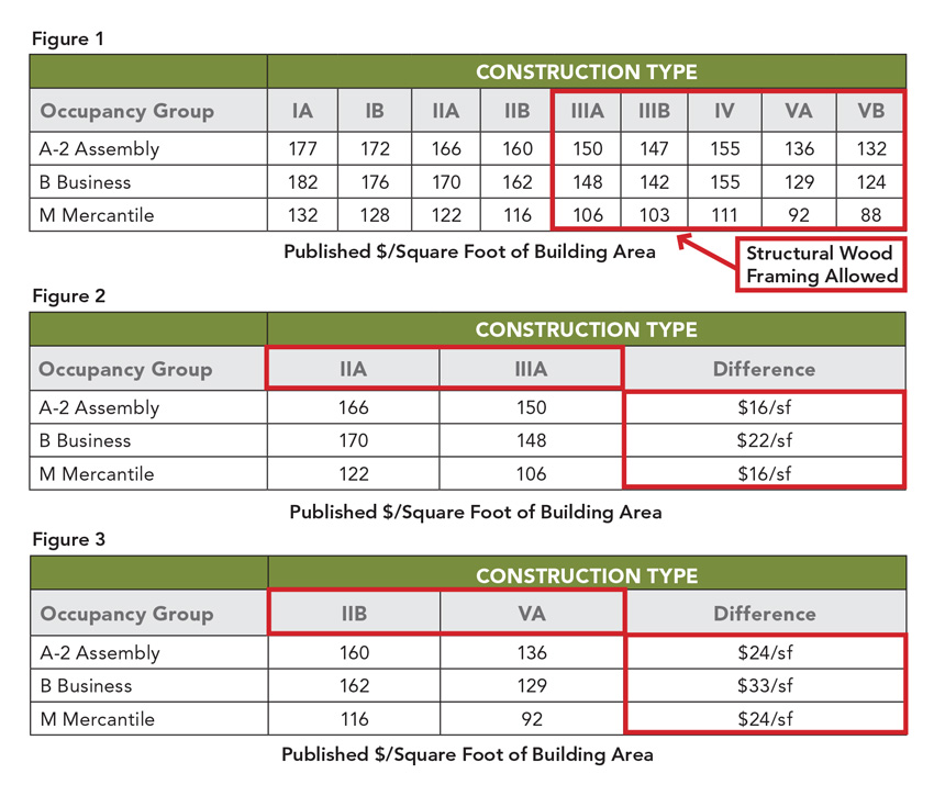
Source: ICC Building Valuation Data, August 2015
Heights and Areas
One of the changes in the 2015 IBC compared to the 2012 version is a restructuring of the section on heights and areas. The equations are simpler, but there are more of them, along with more tables that are also larger and more complex. Among the specific changes there are separate tables for allowable heights (IBC Table 504.3) and allowable stories (IBC Table 504.4), with results based on occupancy classification, construction type, and whether the project is sprinklered.
Although Types IV and V may be more appropriate depending on the objectives of a project, architects interested in choosing wood structures should be aware that almost any low-rise commercial building can be designed in wood using the Type III designation. For common low-rise commercial and mixed-use occupancies (Assembly, Mercantile, Business, and Residential), Type II and Type III Construction in IBC 2012 and 2015 have equal building height and story limits.
DIAMOND FOODS INNOVATION CENTER


Photos: Eckert & Eckert
Location: Salem, Oregon
Architect: ZGF Architects
Engineer: KPFF Structural Engineers
Designed to complement and expand an existing warehouse and shipping facility, this 7,350-square-foot office includes a partial second story and multiple double-height spaces. Walls are traditional wood-frame construction using 2-by-4 and 2-by-6 dimension lumber; the truss roof includes glulam and exposed structural tongue and groove decking; and the floors are comprised of wood I-joists with glulam in select areas. The facade is an innovative combination of Douglas-fir wood siding and heat-treated pine.
Opportunities for Unlimited Area
To determine allowable height and area, many designers look to the IBC tables covering occupancy versus construction type (IBC Table 506.2) and use the equations to determine the tabulated limits for their buildings. Sometimes overlooked is the fact that commercial projects of Type III, IV, and V Construction—including Assembly, Education, Business, Factory, Mercantile, and Storage Occupancies—may qualify for unlimited area in IBC Section 507. This is because of the open space that often surrounds commercial projects, such as parking lots and major roadways, which, in addition to sprinkler protection, increases safety by providing firefighting access to multiple sides of the building.
The typical baseline requirement is 60 feet or more of open space on all four sides. However, a project may still qualify for unlimited area if a portion of the building has as little as 40 feet of open space—if the exterior walls and openings on the side with the reduced frontage have a 3-hour fire-resistance rating.
Where a project includes multiple buildings that are less than 40 feet apart—such as a group of offices or retail stores—the IBC allows them to be considered as a single building for the purpose of determining whether unlimited area applies, providing they have 60 feet of open space around them, and provided they would all otherwise qualify for unlimited area.
Two-story buildings of Business, Factory, Mercantile, and Storage occupancies of any construction type can have unlimited area providing they have the required surrounding open space and are equipped with a National Fire Protection Association (NFPA) 13-compliant automatic sprinkler system (IBC Section 507.5). Additional allowances for Assembly occupancies related to unlimited area buildings can be found in IBC Sections 507.4 and 507.7.
BIG BOX RETAIL: WOOD SAVES NEARLY $1 MILLION
Cost and environmental studies compare wood to steel

To evaluate the opportunity for wood use in the commercial building subcategory known as big box retail, WoodWorks commissioned two studies—one cost comparison and one life-cycle assessment (LCA)—on the same big box project designed in steel versus wood.
Having received the drawings for a one-story, 54,800-square-foot steel-frame big box store in California, WoodWorks commissioned the design of a comparable building using wood materials. The two designs share the same geometry, structural layout, and column grid. They also have the same gross floor area, floor plan, and layout.
According to the cost comparison, the wood building design saved an estimated 22 percent, or $988,626, compared to the steel building design. The largest cost savings were associated with the structure and roof insulation. Structure cost savings associated with the wood design totaled approximately $425,000. In order of highest to lowest savings, they were concentrated in roof framing beams, roof decking, roof framing columns, primary roof framing such as trusses and joists, and wall framing. Savings associated with roof insulation represented the largest single element savings (more than $400,000) due to the cost difference between rigid insulation (steel design) and batt insulation (wood design).
The LCA study concluded that the impacts of the proposed wood building are lower than the steel building for all indicators except ozone depletion, where the proposed building results were 5 percent higher. Impacts were analyzed from raw materials through demolition/disposal and also with the additional stage of recovery/reuse/recycling. Highlights through demolition/disposal include:
- Global warming potential: Wood building saves 642 metric tonnes of carbon dioxide equivalent (CO2e).
- Nonrenewable energy use: Wood building saves 9,116 gigajoules (GJ).
- Raw material supply and manufacturing: Wood building has an average of 30 percent less impact across all indicators.
- End-of-life transport: Wood building has 11 percent less impact across all indicators.
Adding the recovery/reuse/recycle stage had minor effects on the overall comparison between the wood and steel buildings. As with the analysis excluding this stage, the wood building outperforms the steel building overall and for all indicators except ozone depletion potential, where the proposed building results were slightly higher.
Detailed information on these studies is available in the WoodWorks report, which includes a section on opportunities for big box wood design.1

BMR/ECO ATTITUDE STORE CONCEPT
Locations: Saint-André-Avelin, Sainte-Agathe-des-Monts, Saint-Jean-sur-Richelieu, Québec
Architect: Sophie Tétrault Architecte
Engineers: Rochon Experts-conseils S.I.M. Experts-Conseils AP Consultant
Founded in 1967 by a group of Quebecois building supply dealers, BMR seeks to incorporate regional materials into its member stores. Wood reflects the company’s heritage while its natural warmth enhances clients’ shopping experience. In addition to providing a more energy-efficient structure, an article in Les Affaires acknowledges sales increases attributable to the wood structure.
Multi-Tenant Buildings
For commercial buildings, determining allowable height and area typically includes considerations related to multiple tenants or occupancies. For example:
- Incidental uses (IBC Section 509) are those that pose greater risk of fire than the main occupancy, such as machine rooms, laundry rooms, and mechanical equipment rooms. Providing they comprise no more than 10 percent of the area of the given story and have the required fire separation, smoke separation, and/or NFPA 13-compliant automatic sprinkler systems, they are not classified as a separate occupancy for the purpose of determining allowable building height and area.
- Accessory occupancies (IBC Section 508.2) don’t pose the same level of risk as an incidental occupancy and therefore do not have the same dedicated passive or active fire safety requirements. To qualify as an accessory occupancy, the area must comprise less than 10 percent of the story area and the IBC 506 “NS” allowable limit value. For commercial buildings, no separation is required between the accessory occupancy and the main occupancy, and only the main occupancy needs to be considered when calculating height and area. Examples include storage in an office or kitchen in a community space.
- Nonseparated occupancies (IBC Section 508.3) have another level of restriction in terms of fire protection systems (IBC Chapter 9) and allowable height and area, as well as other requirements based on the most restrictive occupancy of the mix. However, the advantage is that they don’t require specified fire-rated assemblies between occupancies. An example would be the same office/storage scenario, but where the storage comprises more than 10 percent of story area. To check the allowable heights and areas of nonseparated occupancies, the nonseparated occupancies should be checked as if the entire area consists of each of the contained occupancies, with the most stringent check governing the allowable height and area of the nonseparated occupancies.
- Separated occupancies (IBC Section 508.4), as the name suggests, require fire-rated assemblies between occupancies. This separation allows for larger allowable areas than nonseparated occupancies, while allowable height is based on occupancy—i.e., the IBC allows a specific elevation or number of stories for each occupancy group. Because of this, an architect may be required to put certain occupancies on lower versus higher floors.
A good resource for height and area analysis is the 2015 Code Conforming Wood Design, a joint publication of the ICC and American Wood Council (AWC), available at www.awc.org. WoodWorks also offers a free downloadable Heights and Areas Calculator, available at www.woodworks.org, which reviews and analyzes building height and area compliance with the 2015 IBC for buildings up to six stories, with up to four occupancy groups at each level.
Fire Resistance and Detailing
Types I, II, III, and V Construction are further subdivided into two categories (IA and IB, IIA and IIB, IIIA and IIIB, and VA and VB) with the difference being the degree of fire resistance required for various building elements and assemblies. For example, in Type VA Construction, all interior and exterior load-bearing walls, floors, roofs and structural members are required to have a minimum 1-hour fire-resistance rating. In Type VB Construction, no fire-resistance rating is required.
While a detailed discussion of fire resistance is beyond the scope of this course, there are many sources for tested fire-rated assemblies. Fire-rated wood-frame assemblies can be found in publications such as:
- Underwriters Laboratories’ (UL) Fire Resistance Directory
- Intertek Testing Services’ Directory of Listed Products
- Gypsum Association’s Fire Resistance Design Manual
ACRE COFFEE

Photo: Russell Abraham Photography
Location: Santa Rose, California
Architect: Hedgpeth Architects
Engineer: MKM & Associates
This 7,233-square-foot restaurant and coffee shop features a wide range of wood products. The roof is dimension lumber and Alaskan yellow cedar glulam; the walls are LVL, LSL, and PSL; and the exterior siding was milled from redwood members reclaimed from the site’s previous building. Acoustical ceilings are made from Douglas-fir planks, spaced to allow sound to be absorbed by cavity insulation between the ceiling and roof.
Wood Building Systems
Building designers interested in using wood for commercial projects have a variety of options, from exposed mass timber systems using innovative products such as cross-laminated timber (CLT), nail-laminated timber (NLT), and glued-laminated timber (glulam), to traditional dimension lumber framing that can be used to economically and effectively meet the objectives of almost any low-rise commercial project.
Wall Framing
Options for wall framing include solid sawn and finger-jointed dimension lumber, glulam framing, and structural composite lumber (SCL) products.
Ceiling height is the primary driver of wall height, and it is common for commercial spaces to have ceiling heights of 12 feet or higher. Solid sawn dimension lumber, ranging in size from 2-by-4 to 2-by-12, is commonly used for interior and exterior walls. For posts under concentrated load locations, 4-by and 6-by solid sawn lumber may be available depending on the region. Designers can also use multiple 2-by members nailed together to create larger composite members.
Again depending on the region, structural framing lumber is available in four main species groups: southern pine, Douglas-fir-larch, hem-fir, and spruce-pine-fir. Lumber in each of these groups can be made from a range of species as defined by the grading rules. Visually graded lumber is the most commonly used, with grades that include select structural, #1, #2, stud grade, etc. In some areas, machine-graded lumber may also be available, including machine stress rated (MSR) and mechanical evaluated lumber (MEL). Because product availability varies widely, designers are advised to consult with local distributors and industry experts to determine which products are most appropriate for specific applications.
Related to dimension stud lumber is finger-jointed lumber (referred to as ‘end-jointed’ lumber in the IBC), which is comprised of shorter sections of wood glued together into longer members. Per IBC Section 2303.1.1, if approved for the building application, properly graded and stamped finger-jointed lumber can be used interchangeably with the same grade and species of solid sawn lumber. Some finger-jointed lumber is labeled as “vertical use only” or “stud use only.” This lumber is not appropriate for nonvertical uses, such as headers, beams, joists, or anywhere sustained bending or tension loads are expected. For fire-rated assemblies, finger-jointed lumber must be stamped “HRA” to indicate that a heat-resistant adhesive was used in its manufacture.
Glulam framing is manufactured using small pieces of lumber that are glued together to make significantly larger beam and column elements. Glulam beams are manufactured in a variety of sizes, with custom products greater than 4 feet deep and 100 feet long available.
SCL is made from a variety of wood fiber products smaller than dimension lumber, such as veneers, and strands. This category of products includes laminated veneer lumber (LVL), laminated strand lumber (LSL), parallel strand lumber (PSL), and oriented strand lumber (OSL). These products are often used for floor beams under heavy loads and as studs in tall walls (see section below).
Manufacturers offer some glulam and SCL products specifically sized for wall applications. They can also be used for headers, heavily loaded trimmers and jacks, and sometimes posts (though solid sawn is more frequently used for this application).
While detailed structural design is beyond the scope of this course, it is valuable to know the high-level approaches to structural code compliance in framing design—i.e., prescriptive versus engineered.
With prescriptive framing design, applications suitable for each framing approach are defined and the calculation of loads onto framing members is not utilized. Prescriptive approaches applicable to some commercial buildings can be found in IBC Chapter 23 (conventional construction), and portions of the Wood Frame Construction Manual (WFCM), a referenced standard published by AWC. In both cases, the scope of the prescriptive approach is limited to 40 pounds per square foot (psf) live load on wood floors, which limits their use to commercial occupancies on the ground floor.
With an engineered approach, the wood framing system is designed to handle code-required minimum loads as defined by the IBC and referenced standards, with loading often calculated using ASCE 7-10: Minimum Design Loads for Buildings and Other Structures, and wood framing commonly designed in accordance with AWC’s National Design Specification® (NDS®) for Wood Construction, and Special Design Provisions for Wind and Seismic (SDPWS). The WFCM also provides an engineering approach to wood framing components.
Tall Wall Design
Although defined as ‘low-rise,’ many commercial structures require ‘tall walls’—20 feet and taller—to achieve desired interior heights. Wood is both appropriate and effective in these applications.
Wood-frame tall walls offer the same benefits as other wood stud walls:
- They’re able to resist snow loads on the roof and wind loads on the wall, without requiring an additional load-bearing frame.
- When wood sheathing is added to studs, the wall is effective at resisting the lateral racking loads caused by high wind and seismic events.
- They can be easily insulated to provide excellent thermal resistance.
- They can be finished with a wide range of finishing materials.
- And they can be easily modified to adapt to changing tenant/owner needs.
For commercial structures, larger lumber sizes and engineered wood products can be used to obtain the same strength for walls that are taller and longer. Shear walls and connections can be easily designed to provide the required lateral resistance. Thermal requirements can be achieved with insulation. And, by paying attention to details and selecting appropriate finishing materials, tall stud walls can meet or exceed the more stringent fire separation requirements associated with most commercial structures.
Although the design of tall walls tends to be the purview of structural engineers, it is helpful for architects to understand two nuances that can have a significant impact on cost. For example:
- While a designer may wonder what is required to reduce the weak axis unbraced length of wall studs, the NDS Commentary says that any code-accepted wall sheathing, which includes wood structural panels and gypsum board, is valid. At the same time, it is important to have mid-height wall stud blocking to brace the stud during construction, as there will be loading before the sheathing or gypsum is installed.
- If ASCE 7 is used to calculate wind loads for components and cladding, structural components and connections that will be subject to wind from a larger area may have reduced loading requirements. This is similar to a live load reduction factor.
For a fast review of wall stud checks, the WFCM includes tables of allowable spans for different stud sizes and grades under various wind and gravity loading conditions and locations in the building.
EXAMPLES OF TALL WALL CONSTRUCTION

Photos courtesy of WoodWorks
This restaurant in California includes 24-foot walls made from 2-by-8 Douglas-fir.

Photos courtesy of WoodWorks
This jewelry store in Tennessee includes 22-foot walls made from 2-by-8 Douglas-fir. Prefabricated off-site, the walls were delivered with insulation and brick veneer already installed.
Wall Bracing
While prescriptive braced wall panels are an option for wall heights up to 12 feet (covered in IBC Chapter 23 and the International Residential Code), this section focuses on the more commonly used engineered wall systems for lateral force resistance, including:
- Engineered wood structural panel-sheathed shear walls
- Prefabricated shear wall products
Shear walls have four main components or component systems—wall framing, sheathing, base anchorage, and end posts—which function both individually and together as a unit. Wall framing includes studs, blocking between studs, and sole and top plates. Sheathing includes wood structural panels as well as their attachment to the wall framing. Base anchorage includes any attachment method used to anchor the base of the shear wall to the wall/floor/foundation below to resist unit shear and unit uplift (if applicable). This could be done with anchor bolts into the foundation, or nails, wood screws, or lag screws into a wood-frame wall or floor below. End posts, also known as boundary members, are located at each end of the shear wall and resist the overturning tension and compression forces. Load path for tension forces is developed through the use of hold-down systems, which tie the end post to the foundation or framing below.
Requirements for nailed shear walls, including in-plane unit shear capacities and construction details, can be found in the SDPWS. The following three shear wall design approaches are recognized in the SDPWS and widely used:
- The segmented shear wall approach uses full-height shear wall segments with no openings, each with full end restraint against overturning.
- The force transfer around openings (FTAO) approach utilizes strapping to transfer forces around openings.
- The perforated shear wall method provides a way to account for the strength and stiffness of shear walls with openings, while providing an alternative to the strapping around openings required by the FTAO method.
For large open-front buildings, where the maximum height-to-width aspect ratio of wood structural panel-sheathed shear walls of 3:5 to 1 may not be available, a variety of prefabricated narrow shear wall systems are available. These panels can be wood-frame or a combination of wood and steel-frame. They generally utilize the concept of segmented shear wall design, with the exception that some are intended to be used in tandem to create a portal frame system. Designers considering the use of these systems should be aware of the following:
- Because they’re quite narrow, the magnitude of hold-down forces at the ends of the wall can be significant, making the anchor bolt detailing and construction critical.
- Some of these systems have relatively large in-plane deflections at their full load capacity, making it important to account for the effect of large deflections on performance of wall finishes such as gypsum wallboard.
- While there are some similarities among them, they’re proprietary systems and a designer can be locked into a specific design without any flexibility for field modification.
Deflection compatibility with other walls is another design consideration. The common assumption of distribution of load (on a pounds per lineal foot of wall basis) does not apply when mixing prefabricated shear walls with wood structural panel-sheathed shear walls. Guidance on distribution of load based on deflection compatibility can be found in the SDPWS and the technical support documents provided by manufacturers.
These systems also result in very large uplift forces on the hold downs to the point that post-installed concrete anchorage systems typically don’t work. Rather, cast-in-place concrete anchorage (with careful coordination of the framing and anchorage installation) is often required.
Another option that may be available is to design a building with no shear walls on one side. In the 2008 SDPWS (and earlier), there were two design approaches that allowed this—cantilever diaphragms and open-front structures—each with its own (though similar) requirements. In the 2015 SDPWS, these concepts have been combined, as shown in Figure 4. In the 2015 SDPWS, a cantilever diaphragm is a horizontal floor or roof system that distributes horizontal loads to shear walls and is not laterally supported at one edge. An open-front structure is a structure with a cantilever diaphragm.
NEW HEIGHTS PHYSICAL THERAPY
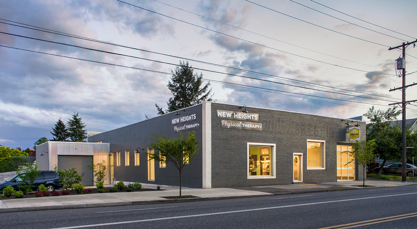
Photo: Eckert and Eckert Photography
Location: Portland, Oregon
Architect: Constructive Form Architecture and Design LLC
Engineer: James G Pierson Inc.
This 7,000-square-foot office recently underwent a major adaptation from a metal shop to an Assembly/Business occupancy. The roof is a mix of dimension lumber, glulam, LVL, LSL, and PSL. Flooring is comprised of I-joists, glulam, LVL, LSL, and PSL. Walls are dimension lumber studs.
Figure 4: Open-Front Structures
The 2015 SDPWS unifies cantilever diaphragms and open-front structures.
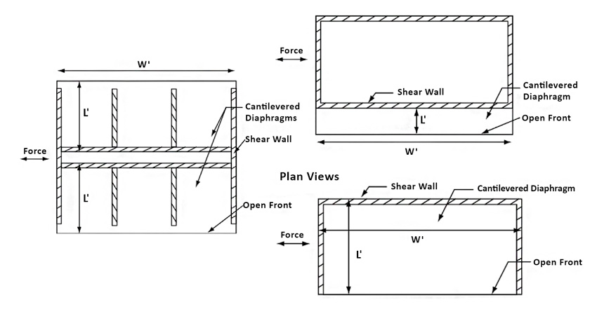
Image courtesy of the American Wood Council
Figure 5: Three-Sided Open-Front Structures
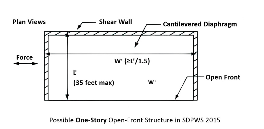
Image courtesy of the American Wood Council
Image courtesy of the American Wood Council
Figure 5 illustrates an example of what’s possible for single-story, low-rise, open-front building types with shear walls only on the back wall. The maximum length of the roof from the open front to the back shear walls (L') is 35 feet. The width (W') of such a one-story building is allowed to be equal or greater than L', so square (e.g., L'=35 feet, W'=35 feet) and long (e.g., L'=35 feet, W'=200+ feet) buildings are possible using this approach. In some cases, narrow buildings with W' not less than L'/1.5 (e.g., L'=35 feet, W'=23.3 feet) are possible. For exact requirements, designers should refer to the SDPWS. Such open front buildings may be useful for smaller retail or office buildings. With a building deeper than 35 feet, options include adding an interior shear wall line to reduce the cantilever length to 35 feet, or placing shear walls or other lateral force-resisting elements along the front side of the structure.
Roof Framing
There are many wood options available to achieve the long spans typical of commercial building roofs.
Truss Roofs
Although trusses are often associated with the pitched roofs of single-family homes, they come in a seemingly infinite range of profiles and sizes, with some spanning over 80 feet. Trusses are strong, quick to install, and economical. They’re also highly versatile. Designed using sophisticated software, they can be manufactured in complex shapes and unusual configurations, accommodating arches, for example, or enabling companies to incorporate features distinct to their branding. They’re also compatible with other materials, and their open-web configuration allows easy placement of mechanical, electric, and plumbing (MEP) services.
Designers can choose from metal-plate connected wood trusses or timber trusses. Metal-plate connected wood trusses are made from dimension lumber joined together with metal connector plates and are among the most economical wood roof systems. Timber trusses can be made from solid or engineered wood members. They are highly engineered and typically left exposed as an architectural feature.
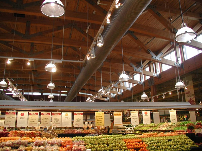
Photo: Scott Lockyear, WoodWorks
The roof of this 15,000-square-foot Whole Foods Market in Atlanta, Georgia, spans 67 feet. It is comprised of 60-inch-deep glulam trusses spaced 14 feet apart, 2-by-6 tongue and groove southern pine planks supported on glulam beams, and 8-by-8 columns at 20 feet on center.
I-Joist Roofs
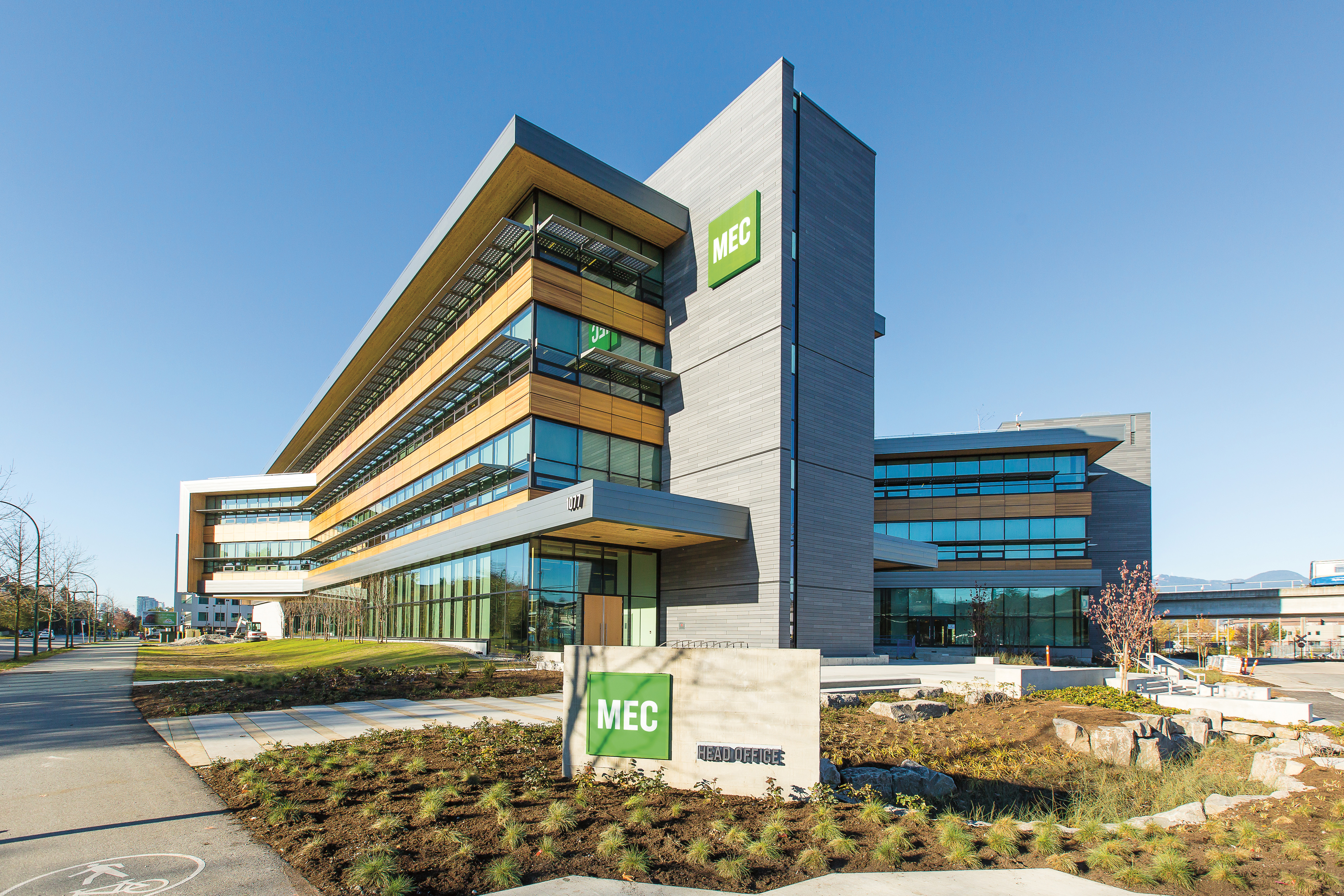
MOUNTAIN EQUIPMENT CO-OP (MEC)
Location: Vancouver, British Columbia
Architect: Proscenium Architecture + Interiors
Engineer: Fast+Epp Structural Engineers
Photo: KK Law
Canada's biggest retailer for outdoor gear chose wood for its environmental and biophilic benefits. The structure is constructed with laminated timber beams and columns, joined and braced with steel fittings. A double-beam configuration serves double duty; the exposed beams give warmth and architectural interest to the interior and their increased stiffness reduces deflections and floor vibrations.
I-joists are comprised of top and bottom flanges, which resist bending, united with webs, which provide excellent shear resistance. The flange material is typically solid sawn lumber or LVL, and the web is made with plywood or oriented strand board (OSB). I-joist framing is commonly used for flat and low-slope roofs with spans up to approximately 30 feet. Sloped roof applications also provide vaulted ceiling opportunities.
In one common configuration, wood I-joist roof systems are framed with a central bearing wall or beam that carries roof loads to the posts. Loads from the top half of the roof are carried by the bearing wall or beam, and loads from the bottom half are carried by exterior bearing walls. Loads are primarily gravity loads, which push down, not out, on the bearing walls.
Information on design and installation of I-joist roofs can be found in the APA publication, Performance Rated I-Joist Roof Framing Details, and AWC’s Manual for Engineered Wood Construction.
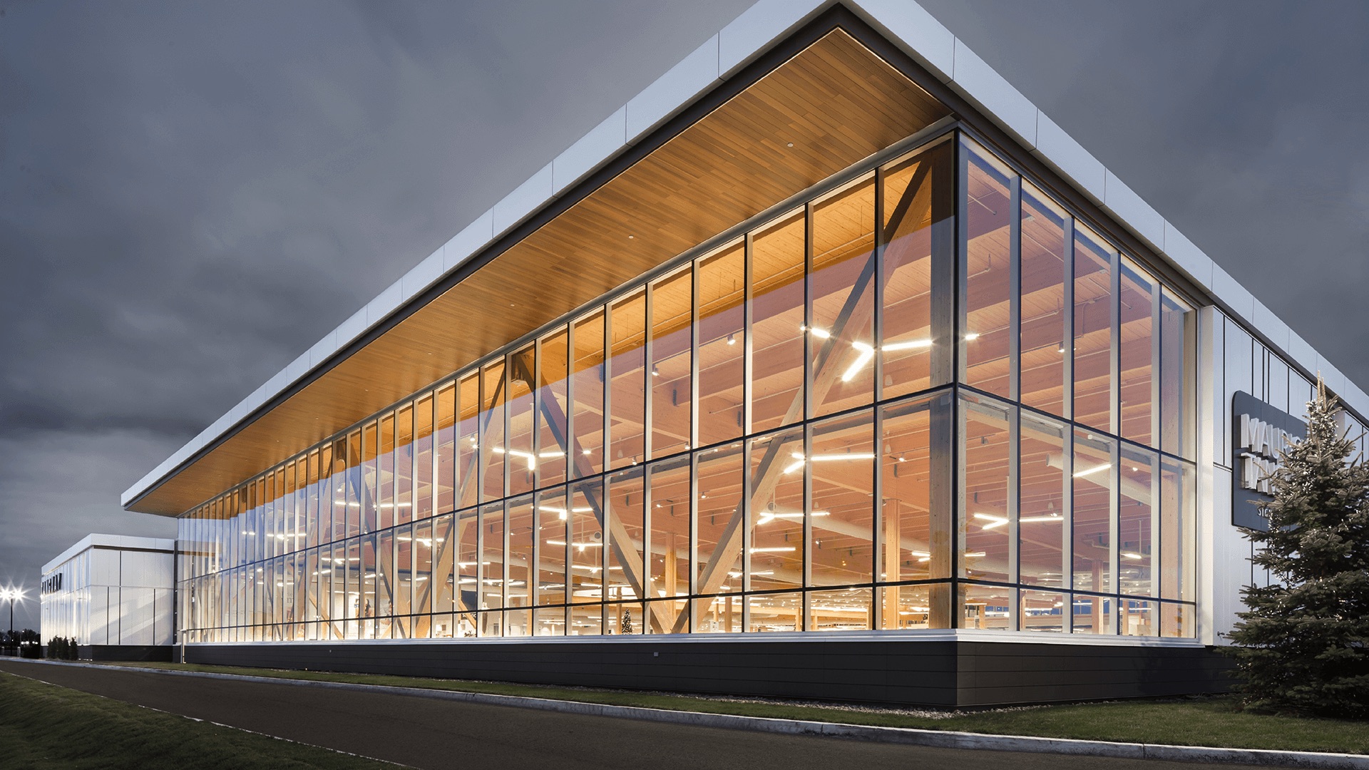
TANGUAY FURNISHINGS
Location: Trois-Rivières, Québec
Architect: Coarchitecture
Engineer: Nordic Structures
Photo: Stephane Groleau courtesy Nordic Structures
Glued-laminated timber (glulam) post-and-beam construction serves as the primary structure for this 80,000 square-foot retail furniture showroom. Glulam decking forms the expansive ceiling while a cedar soffit gives the interior and exterior structures visual continuity. The long-spanning 50-foot beams provide the customer with uninterrupted views of merchandise and facilitate enhanced wayfinding.
Large, Flat Roof Systems
For large projects such as grocery or big box retail stores—which can have grid dimensions of 45 feet by 50 feet or larger—panelized roof systems can be a cost-effective solution. According to one roof erector, panelized wood roofs on the West Coast can save $1.25 to $1.50 per square foot over conventional steel joist metal deck systems.2 Savings can be attributed to, among other things, material costs, speed of installation, and insulation. This is also supported by the cost comparison described in the sidebar, Big Box Retail: Wood Saves Nearly $1 Million.
In North America, both all-wood and hybrid panelized roof systems are common.
All-wood systems tend to be used for spans of 40 feet or more, and are particularly well-suited for applications where conveyer equipment is hung from the roof structure or in food processing facilities that need to minimize dust from overhead joists. They are also a good choice for developers and designers who want to take advantage of wood’s aesthetic benefits for an exposed roof structure.
In a typical all-wood system, sheathing or wood structural paneling spans between sub purlins, which are 2-by-4 or 2-by-6 dimension lumber, depending on the span. Sub purlins span between purlins, which can be glulam, I-joists, metal-plate connected wood trusses, or wood flange metal web trusses, and the purlins span between girders, or girders and exterior walls. Girders are typically glulam beams, either simply supported or with cantilevers. That said, there are many possibilities for the design of large, flat wood roofs, including options with no sub-purlins but longer-spanning decking products, such as tongue and groove timber or laminated decking and mass timber.
Parapets are a common feature of many flat roofs, providing space for signage and hiding mechanical units. Framing options include:
- Tall stud parapets, where the wall framing extends past the roof frame so the parapet is a continuation of the studs themselves
- Built-up parapets, where the studs stop at the top of the wall and the parapet is built on the roof (requires bracing)
- Truss parapets, where the parapets are built into the trusses themselves during manufacture
For large, flat roof applications, unlimited areas can be achieved under IBC Section 507. However, designers of low-rise commercial and industrial applications may also design large roofs under standard provisions of IBC Chapter 5 using sprinkler increases and the sub-notes included with IBC Table 601.
The SDPWS includes information on high-load diaphragm design useful in panelized roofs. High-load wood diaphragm design with multiple rows of nails (accommodating ASD capacities up to approximately 1,500 plf for seismic and 2,000 plf for wind) is possible in configurations using tall and/or heavy wall systems, especially in combination with very large diaphragms.
SUPPORTING COMMERCIAL WOOD BUILDING DESIGN
For individuals involved in the design, construction, review, and approval of commercial buildings, WoodWorks and the American Wood Council offer a variety of resources at no cost.
For more detailed information on the subjects covered in this CEU, a new version of the American Wood Council’s Code Conforming Wood Design based on the 2018 CCWD is available as a free download at www.awc.org.

Project support: WoodWorks provides free project assistance, as well as education and resources related to the code-compliant design, engineering, and construction of nonresidential and multifamily wood buildings. www.woodworks.org

Codes and standards support: Expert staff at the American Wood Council develop state-of-the-art engineering data, technology, and standards for wood products to assure their safe and efficient design. They also provide information and education on wood design, building codes, and green building. www.awc.org
End Notes
1“Big Box Retail: Wood Saves Nearly $1 Million.” (2015): 1-12. WoodWorks Case Study WW-019: Big Box Retail Comparison. WoodWorks,
www.woodworks.org/wp-content/uploads/Big-Box-Retail-Wood-vs-Steel-Oct-2015.pdf
2“Faster, Safer, Lower Cost: Panelized Roof Systems.” (2012): 1-8. WoodWorks Case Study WW-008: Panelized Roof Systems. WoodWorks, www.woodworks.org/wp-content/uploads/IS-Panelized-Roofs.pdf
|
|
Think Wood is a leading education provider on the advantages of using softwood lumber in commercial, community and multifamily building applications. We introduce innovators in the field to our community of architects, engineers, designers and developers. For support or resources, contact us at info@ThinkWood.com. |