Active Chilled Beams Come of Age
Architectural integration and application of this energy-saving technology meet sustainability and aesthetic goals
![]() Continuing Education
Continuing Education
Use the following learning objectives to focus your study while reading this month’s Continuing Education article.
Learning Objectives - After reading this article, you will be able to:
- Compare the energy efficiency of a traditional heating ventilating air conditioning system to a chilled beam system.
- Discuss the design considerations of an active chilled beam in promoting an energy efficient, aesthetic, cost-effective solution that meets green building goals and the safety and well being of building users.
- Explain the issue of condensation and how it can be controlled for optimum functioning of an active chilled beam in the context of a sustainable application that supports indoor air quality.
- Specify a chilled beam application that is appropriate for a particular building type in order to increase energy efficiency and enhance occupant comfort.
Building energy efficiency, sustainability, and interior aesthetics are concepts that may often appear to be at odds. Yet designers must balance these concepts within budget restrictions and energy code requirements—a feat, say industry experts, that will be increasingly hard to achieve. The “Annual Energy Outlook 2014” published by the U.S. Energy Information Administration (EIA) estimates that between 2012 and 2040, commercial building energy consumption will grow by 0.6 percent annually, while the growth of commercial floor space averages 1.0 percent per year and the energy intensity, or energy use per square foot, will decrease by 0.4 percent per year. This decrease is expected to come from federally mandated gains in equipment efficiency and reduced consumption by space heating, cooling, lighting, and plug loads. The key takeaway here is that, again, over time, it will become increasingly difficult to balance the energy code requirement, budget restrictions, and interior aesthetics.
How then can design goals be met while reducing energy?
Traditionally, most buildings have used air movement to transfer both the fresh air and thermal energy needed to properly heat, cool, and ventilate occupied spaces. Air, however, is not a very energy-dense media, and significantly more air is often required to cool a space than to provide fresh air.
The requirement for high volumes of air to condition the building and the inherent inefficiency in moving air around the building have presented considerable challenges in using the traditional all-air HVAC design approach to meet increasingly restrictive energy codes. As a result, industry experts are exploring alternative methods. Water, for example, is often considered as the transport media of choice for energy-efficient thermal energy transfer. Water can store significantly more thermal energy per unit volume than the same volume of air, and because it has a higher energy density and a higher pumping efficiency, water requires less transport energy—by pump rather than by fan—to move thermal energy into and out of the occupied spaces. When used as the sole media to provide building heat and cooling needs, water has a lower operational cost than an equivalent all-air system. Of course, a certain amount of air movement is required for the proper ventilation of the occupied space. However, an air-water HVAC system that provides only ventilation-required air volumes can lead to an estimated reduction in building mechanical system power of 15 to 40 percent or more in some situations, depending on the overall system design.
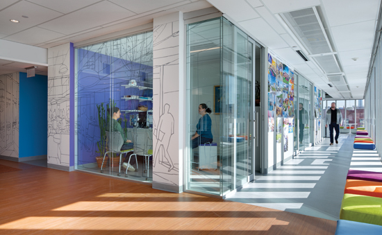
HMFH Architects, Inc. Corporate Office. Photo © Ed Wonsek.
Active chilled beams have energy-saving potential in all building types.
Active Chilled Beams—A Proven Alternative
One alternative technology to an all-air system that is gaining traction is the active chilled beam, which incorporates the distribution of the ventilation air and uses room air induced across a water coil to transfer sensible thermal energy for both heating and cooling to the occupied space. When active chilled beams were first introduced in the North American market, they were limited by their capacity and their inability to meet aesthetic and architectural integration goals. Today's high-efficiency versions, however, can be seamlessly integrated in the buildings of the most demanding customers. In fact, active chilled beams have been used in Europe for over 20 years and were initially used primarily in high-performance office and educational buildings in the United States. As energy-efficient HVAC designs have become more common, many designers are using chilled beams in all types of buildings and finding that along with energy savings, occupant thermal comfort is also enhanced by better air distribution and thermal control of the occupied zone. The potential exists for chilled beams to have a significant role in both new construction and renovation of existing structures. Reed construction data indicates an increasing use of chilled beams in the U.S. market, with educational facilities and the commercial market representing the top two user groups. Healthcare facilities have just started using chilled beams as standards such as ASHRAE 170 Ventilation of Healthcare Facilities now allow chilled beams in patient rooms.


Source: Reed Construction Data and Price Industries
Benefits and Drawbacks
Active chilled beams may not be appropriate for all building/occupancy types, and their benefits and drawbacks should be evaluated in light of a particular application. Among their benefits, chilled beams have no internal moving parts and consequently little to no maintenance requirement compared to the traditional all-air VAV (variable air volume) system. They are also more efficient than their traditional VAV counterparts. A chilled beam system using a dedicated outdoor air system (DOAS) may see a reduction of 50 to 80 percent less primary air transport than that required in the traditional all-air VAV system. This lowered volume of primary air can lead to reduced floor-to-floor height as chilled beams do not need as much interstitial space for ductwork and have smaller mechanical room footprint requirements.
Due to the energy density of water compared to air, it takes about 1/10 the energy to move the same amount of thermal energy with water than air. Further, it is easier to achieve superior mixed air distribution with chilled beams—a scenario that leads to higher levels of occupant thermal comfort. In addition, when primary air is kept to a minimum, chilled beams offer quiet operation.
Despite their advantages, there is a lack of familiarity with chilled beams among MEP engineers, contractors, occupants, and building owners. The most common perceived issue is risk of condensation. However, this is not a concern if the mechanical system is designed to manage the dehumidification load and the building envelope has good control of moisture infiltration. Space is an important consideration. Chilled beams may occupy a higher percentage of ceiling area than traditional VAV, and space humidity sensors and condensate sensors are required for the best occupied space humidity control and least risk of condensation. In some instances, chilled beams are not appropriate, notably high-humidity (high latent load) spaces such as kitchens, and spaces that experience high air volume change such as laboratories with fume hoods.
What are Chilled Beams and How Do They Work?
Chilled beams are of two basic constructions: passive and active. Passive beams are cooling-only devices that use gravity-driven natural convective cooling to condition the occupied spaces. Passive beams are typically installed along perimeters of buildings to try to intercept and condition most of the cooling load from the building shell before it reaches the occupied areas of the building.
Active beams are an induction device, where supply air is used to draw room air through a water coil. The air and water both provide cooling or heating depending upon the season. The water coils provide sensible cooling and the supply air handles the fresh air requirements and controls the occupied space humidity levels. The more optimally configured active chilled beam systems use only the ventilation minimum air volume, that is, fresh air, as the supply air; the rest of the sensible heating/cooling is provided by the water coil.

Image courtesy of Price Industries
Air Flow Pattern in an Active Beam
Condensation and Control
As most designers and end users have concerns about the potential for condensation, it is common for the designer to explore using a condensate pan as a safety feature even if the active chilled beam system is designed to not condense. Condensation is the heat transfer process by which water vapor is converted into liquid water, while condensate is the water that collects on the cold surface. The potential for condensate to form on a surface is determined by the difference of the surface temperature relative to the dew point of the air, which is the temperature at which water vapor in the air will become liquid water.

Source: Mumma, 20021
Condensate on panel with temperature differential
Surfaces with temperatures below the air dew point will form condensate. The rate at which the condensate forms is a function of how cool the surface is in relation to the dew point of the surrounding air, as well as the length of time the air is in contact with the cool surface. Since the space relative humidity is typically 50 percent or less, the risk of condensation can be mitigated by keeping the supply water temperature above the design room dew point. This dew point temperature of room air at 75°F and 50 percent relative humidity is ~55°F; therefore chilled surfaces above this temperature should not cause condensation. Engineers typically use a safety factor on this value to account for humidity and supply water temperature fluctuations; therefore supply water temperatures of 58°F are common. Interestingly, when room air is blown across a cold surface, the formation of condensate occurs at lower temperatures than the dew point because the air is moving and the air needs a longer duration of contact that the length of water coil fins used in active chilled beams. Since the cooling coils on a chilled beam are only two rows deep, the coil temperature may be significantly below dew point before water droplets form and fall from the coil fins.
When condensate forms, it is too late to prevent the surface from becoming wet. The question, however, is how to prevent condensate from becoming a design flaw in the building.
The HVAC designer needs to verify that the ventilation system is capable of handling the latent load. Humidity loads that must be addressed include:
• Ventilation load. Generally the largest moisture load, particularly in a humid climate.
• Infiltration load. Moisture that crosses the building shell through windows, cracks, and other penetrations. Non-operable windows and pressurization of the building can minimize this moisture source.
• Occupant load. As people breathe and perspire, moisture is released into the space.
• Other loads. Fountains, doors, and windows left open, wet clothing, etc.
It is important to note that around the world, many active chilled beams installed in humid areas do not have drain pans, nor do they need them. That said, most building codes have historically required drain/condensate pans for cooling coils. Recently, the chilled beam section at the Air-Conditioning, Heating and Refrigeration Institute (AHRI) filed an interpretation request with the International Code Council (ICC) concerning the requirement in the International Mechanical Code (IMC) that cooling coils must have a drain pan. In response, the ICC added an exception to the 2015 International Mechanical Code removing the condensate drain system requirement for cooling coils designed to operate in sensible cooling mode only and when a design strategy is used to prevent condensate formation on the sensible cooling coils.
How Chilled Beams Work
In a chilled beam, the term “induction” is used to describe the process of injecting primary air under pressure through a nozzle, which in turn entrains surrounding air at the discharge of the nozzle. The amount of air that is entrained vs. the amount of air injected is referred to as the induction ratio. It is important to note that the air pressures that cause this induction are very low so care must be taken when designing a beam (or tailoring a beam for a project) to ensure that there is as low a restriction as possible in the beam to keep the induction ratio high.
The induced air is drawn through a water coil that may either heat or cool the air before it comes in contact with the injected air discharging from the nozzle. The amount of energy transferred by the water coil is influenced by several factors, including the induced air temperature, water supply temperature, volume of induced air moving through the water coil, and amount of coil surface area.
When designing a chilled beam system, one parameter that is often used is the transfer effectiveness (watts/cfm). This is the fraction of heating or cooling energy that is provided by the water coil heat transfer (q water coil) vs. the volume of primary air.
Transfer Effectiveness = q water coil / Q primary air
The transfer effectiveness is related to the overall HVAC system effectiveness. It takes less horsepower to move thermal energy with water than it does with air, as the volume of air needed is significantly larger due to the lower amount of thermal energy it can store. The potential saving is significant, but limited by the system choices made by the designer, as well as the primary air volume requirements. To reach the point of minimal energy consumption used to move air, the primary air volume would be no more than the requirements for fresh air.
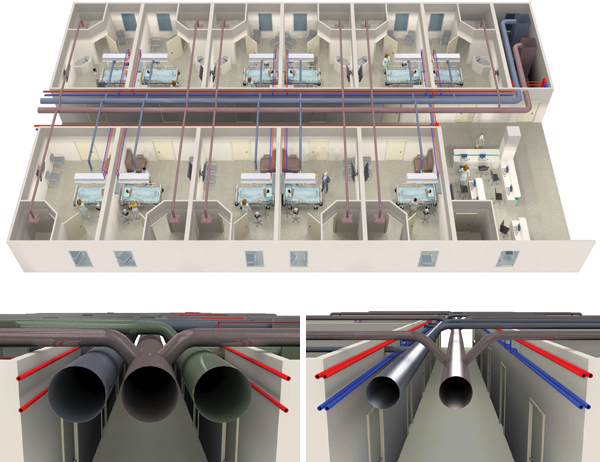
Images courtesy of Price Industries
Hospital patient room hall interstitial space for all-air HVAC system (supply, return, and exhaust) vs. hospital patient room hall interstitial space for an active chilled beam application (supply duct, exhaust duct, chilled water piping)
Minimizing primary air volume is the key to lowered HVAC brake horsepower and higher energy efficiency. Unfortunately, many designers only have experience with overhead mixing air distribution, which requires higher volumes of air, and do not feel comfortable lowering the primary air to the lowest level, leading to less than optimal energy consumption. For example, the accompanying table shows the potential air volume reductions for several different building types. The smaller air-side load fractions indicate the potential for the HVAC designer to use minimal primary air and obtain higher energy savings due to the lowered brake horsepower consumption. If the designer is able to shift the bulk of the sensible load to the water, the building total brake-horsepower has the potential to be reduced to the lowest possible amount, leading to a more efficient design. For example, for an office space, the typical ventilation (outside air) requirements is around 0.15 cfm/sf, but the thermal loads (both sensible and latent) require an all-air system to use as much as 1 cfm/sf, creating a potential for a reduction of 85 percent of the primary air volume. In a classroom, a reduction of 67 percent is possible when designing at ventilation minimums.

Source: ASHRAE Std 62.1 2013 and Price Industries
As a reminder, the HVAC designer needs to verify that the ventilation air is capable of handling the zone latent load.
Benefits of Reduced Primary Air Volume
Active beams can supply2 a significant portion of the sensible cooling or heating load of a building with a relatively low ventilation rate. In most commercial buildings, the ventilation rate required to condition the building can potentially be reduced by up to 85 percent of the ventilation normally required by an all-air system. A study by Weiger detailed the potential benefits of active chilled beams in a hospital setting. Chilled beam HVAC systems in non-surgical spaces such as patient rooms and office areas were found to have the potential to shorten the construction cycle and lower the cost, both initial and life cycle.3
On the scale of the overall system, the reduction in airflow will translate to a smaller air handler and smaller duct network. The reduction in system size may allow a lower floor-to-floor height as well as an increase in usable space on each floor due to a reduced footprint of the mechanical shafts. In certain building types such as healthcare facilities, reducing the congestion in the interstitial spaces will speed construction and allow for more usable floor area due to the significant reduction in the riser spaces needed. Weiger found that the cross sectional ductwork could be reduced by 75 percent with a corresponding reduction of 50 percent material ductwork cost. The riser footprint was reduced by 50 percent and savings in mechanical room footprint was estimated at 25 percent.
The reduction in riser and mechanical room footprints frees that area to be used in revenue-generating activities such as patient rooms. The reduction in riser footprint could in fact allow for an additional patient room on each floor with essentially no additional cost when compared to using a traditional all-air HVAC system. In healthcare applications, when the system is designed to provide 100 percent fresh air at code-required volumes to patient rooms, the return duct may actually not be needed as the exhaust air volume from the patient room bathroom often matches the room supply. It should also be noted that the installation of the ductwork in patient wards is complex and often requires significant coordination and stops and starts from the sheet metal contractors as they allow for other services to be installed. With less ductwork, a common result is that the mechanical system is taken off the critical path of the construction of these wards.
Energy Savings Potential
How much energy can really be saved by active chilled beams? There is no easy answer due to the many systems and possible combinations of equipment available to provide the cooling or heating water. To optimize the choice, designers must consider factors directly related to the HVAC mechanical system energy consumption including: the building geographic location; outdoor humidity levels; occupancy type/schedule; the type/source of hot/warm water; and the potential for primary air volume reduction.
Numerous buildings have incorporated air-water systems that have resulted in greater energy savings than all-air systems. The complete mechanical system supporting the air-water system must be considered, rather than simply picking an active chilled beam and expecting high energy savings. The designer has many choices. Among them:
• Buildings with a central plant with distributed chilled water are in a good position to use chilled beams. The return loop water temperature is very close to the suggested chilled beam supply water temperature. That means that return loop water could be used to provide the cooling effect which, in turn, raises the return loop water temperature and potentially increases the central plant chiller efficiency.
• Using packaged air handling equipment can increase the efficiency of the water system as the plant can be optimized to supply higher chilled water, say 55°F, rather than have to deliver very low temperatures to air handlers for dehumidification, around 42°F. As an example, a centrifugal chiller that delivers chilled water for an all-air system at 42°F may see a 30 percent improvement in the coefficient of performance, when delivering water at a temperature of 55°F.
• Designing the chiller plant to optimize economizer duty—running the cooling towers in parallel with the beam chilled water supply system will lead to an increase in free cooling hours by 25 to 50 percent in most climates.
• If the geology supports ground source heat pump systems, the water temperatures delivered to the building will be very close to the suggested supply temperatures for both heating and cooling using active chilled beams. As a system, this approach has been shown to provide high energy savings and lower operational costs.
Designing with Active Chilled Beams
The integration of active beams in today's building can have a fairly industrial appearance or be fairly unobtrusive, depending on the type of beam and its placement in the occupied space. While traditional chilled beams have had a limited offering of finish options and configurations, this is changing as the product becomes more accepted. Common design options include frame and face style, beam location, induced air opening location, discharge opening location and type as well as the more traditional choices of color selection and frame style.
Frame style can have a significant impact on how well the beam fits with the surrounding ceiling. Options exist for different frame styles that allow the beam face to be flush with the surface for the various styles ceiling tile frames, making for a more consistent finish. Without proper specification, a beam designed to fit in a standard t-bar ceiling may arrive on site, resulting in a distinctly ill-coordinated appearance. In applications where beams are installed in a dry wall ceiling, plaster frames can be used with mud-in style frames offering a more polished look.
The most popular active chilled beam in the North American market is the linear beam. This beam is available in widths of 12 inches and 24 inches and a variety of lengths from 2 feet to 10 feet as a single piece. The linear beam is designed for easy integration in many different types of ceiling grid. The linear active beam can also be installed in a drywall ceiling or suspended from the building slab.
The selection of beam type and integration options may be constrained by the building type, programming, client, and climate. For example, laboratory spaces often have work benches running perpendicular to the façade. In these spaces, it is often desirable to run the mechanical system either above the benches to coordinate with the bench services, or above the aisles. The loads in laboratories will generally require many beams, which will occupy significant ceiling space.

Photo courtesy of Price Industries
The most popular active chilled beam in North America is the linear beam.
It is common in labs, as shown in the image below, to combine multiple beams into a large component, often by selecting options to minimize or eliminate the frames on the end, giving the face and the supply air slots a continuous appearance. It is also common practice to incorporate mechanical returns, controls access, or diffusers to help deliver make up air into the beam so that there are no additional devices in the ceiling which may take up additional space, or which could otherwise be hidden behind the face of the beam.
By so doing, the beam can be a continuous ceiling component while hiding other mechanical services that may be required as shown in the illustration of the linear beam. It is also possible to integrate the beam or beam array with an architectural ceiling system, though careful consideration and testing is often required in order to ensure that the chilled beams perform appropriately. Because of the way the beam works—using nozzles to induce room air over a coil—there must always be an induced air path, a discharge air path, and the required return for the mechanical system.

Image courtesy of Price Industries
Computer lab with beams
These concepts are not only well suited to laboratory spaces, they are also often used in commercial buildings. The option to combine multiple beams into one works well in many spaces. The accompanying figure shows a conference room in Gensler's Los Angeles studio which has several 12-inch wide beams installed end to end to create a single long beam along each wall.

Photo © Gensler / Ryan Gobuty
Gensler’s Los Angeles conference room features beams that have been installed end to end to create a single long beam along each wall.
San Francisco Public Safety Building: A Study in Chilled Beam Integration
The San Francisco Public Safety Building provides an excellent study in chilled beam integration. HOK + Mark Cavagnero Associates and ARUP worked closely with the chilled beam manufacturer to coordinate the beams within a wood slat ceiling system, as well as in perimeter bulkheads.
When placing chilled beams behind a wood slat or metal mesh ceiling, there are some key challenges to consider. The direction of the wood slats should not interfere with the air pattern of the beam. In most cases, this will mean having the beam installed perpendicular to the direction of the slats. The structure of the ceiling should not interfere with the air pattern of the beam. This often poses more challenges than the first consideration as this is generally also perpendicular to the slats. Coordination of this is generally done on a job-by-job basis in combination with laboratory testing to ensure occupant comfort and beam performance. When installing beams behind an architectural ceiling, care must be taken to ensure sufficient free area to allow for the induced air path as well as a path for the discharge air to reach the room below.
Cooling at the Building Perimeter
Curtain wall systems are commonly used in commercial buildings. In cases where the building also features a dropped ceiling, there is often a bulkhead to help transition from it to the ceiling height at the curtain wall. This creates an opportunity for beam installation. A one-way, horizontal style beam is ideal for this application because it tends to be higher capacity than a two-way discharge linear beam and features a one-way discharge pattern to handle the building skin loads.
HOK+ Mark Cavagnero Associates and ARUP used this beam, in combination with a slot diffuser and bar grille to hide the beam in the bulkhead at the SFPSB project. In concept, the bar grille, which was installed with a mud-in frame so that there would be no visible supports, serves as the induced air path for the beam. The slot diffuser was connected to the discharge of the beam to direct air towards the building façade.

Image courtesy of HOK + Mark Cavagnero Associates and ARUP
At the San Francisco Public Safety Building, the slot diffuser was connected to the discharge of the beam to direct air towards the building façade.
Several areas of coordination are required in this installation including detailing how the grille installs in the bulkhead and how the beam will perform with this grille and slot diffuser combination. An added complexity is incorporating a lighting fixture in the same space. When beams are connected to diffusers, it is critical to test the configuration as an assembly because the pressure drop through these devices can have a significant impact on beam performance. As discussed previously, if the pressure drop is too high, the amount of air induced through the beam coil is reduced and the cooling / heating capacity is lost.
To validate the configuration at SFPSB, the design team commissioned a mock-up to test constructability of the bulkhead assembly and to verify beam performance. Once completed, construction details were updated with the lessons learned and the job was constructed.
A few options are available with floor mounted beams, including various face options and finishes. When dealing with a one-way discharge floor mounted beam, integration in existing millwork or architectural features is often possible.
For the displacement cabinet beam in schools, integrating bookshelves and access sections can provide a visually appealing and functional wall-to- wall installation.
Single discharge beams are by far the easiest to integrate seamlessly in a variety of designs. The horizontal single discharge beam, for example, can easily be integrated in the bulkhead of a space. Slot diffusers or bar grilles can be used to hide the beam.
The vertical single discharge beam can also be installed behind the ceiling with a linear vane diffuser or slot diffuser. Return grilles can be located anywhere in the room to allow room air access to the ceiling plenum and to the beam coil.
Case Study
Fraunhofer
Fraunhofer's Building Technology Showcase (BTS) represents the bright future of sustainable design in North America. Fraunhofer Center for Sustainable Energy Systems (CSE) is an applied research and development laboratory that provides R&D and related services for industry and government clients. The BTS is Fraunhofer CSE's headquarters in Boston's fast-growing Innovation District, a deep energy retrofit of a 100-year-old building that serves as a living laboratory for R&D of advanced sustainable energy technologies.
Completed in 2013, the BTS leverages cutting-edge materials and equipment in an effort to facilitate the nationwide adoption of energy-saving technologies. In response to Fraunhofer's challenge to showcase as much innovative technology as possible, the HVAC manufacturer worked with the project design team, DiMilla Shaffer Architects and BR+A Consulting Engineers to evaluate each area and apply a wide range of product, tailored to suit the needs of the space. One example of this is the mechanical system used in the main conference room. This system uses an innovative chilled beam which offers all of the discussed benefits of chilled beam systems, with the additional benefits of displacement ventilation.

Photo courtesy of Price Industries
Chilled beam system coupled with displacement ventilation.
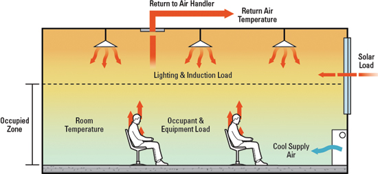
In a displacement ventilation system, cool air is supplied at low velocity and at low level. This allows the cool air to pool at floor level where it is drawn into air currents knows as “thermal plumes” which form around heat sources in the room. These could include occupants, equipment or warm perimeter surfaces. In this way, the cooling air is only supplied to areas in the room where cooling is required, and fresh air is only delivered to occupants as they need it. As this cool air passes over the heat loads, it rises through the occupied zone and up into the area above occupants' heads. Here, the air picks up more heat from lighting, conduction through the exterior walls and is trapped up near the ceiling. In this way, displacement ventilation systems generally only supply enough cooling to meet the loads in first six feet in the room.
The key advantage of coupling a chilled beam system with displacement ventilation-style air pattern can be seen in the figures below. The first figure shows a typical displacement air pattern with supply at low level, warming through the room and returned from high level. This return air is considerably warmer than the room setpoint which is then cooled at the air handling unit. It is important to note that, even though the system only supplies enough cooling to meet the load in the occupied zone, it must still cool the entire room (building) load. The combination chilled beam—displacement ventilation system, in contrast, draws return air in the occupied zone so the air delivered from the air handling unit is only the minimum required to supply fresh air to the occupants. This puts most of the occupied zone on the more efficient water system. The heat loads in the area above occupants' heads is then exhausted from the room and rejected outside the building. This means that the heat picked up after it passes through the occupied zone is not cooled by the mechanical system. The amazing result is that this system has the capability of actually reducing the amount of cooling delivered by the air handlers and chillers. Not only does this mean energy savings vs. the baseline system because there is less cooling, but could also mean less equipment in the first place which would lead to lower first cost.
This product is generally located along the perimeter below windows, but could be located on any interior wall as well. The casing front must have some free area to allow air movement, with either perforated holes or a louvered style panel. It is not uncommon for these to also feature a controls cabinet that is the same size as the beam, thereby allowing easy access for the maintenance team, while having them located in a tidy cabinet that matches the look of the beams themselves. When these are located in school classrooms, one of the largest markets for this style of beam, it is also common to fill in the spaces between the beams (running the full length of the room is not often required) with matching book cases, thereby offering storage on top and between the units.

Images courtesy of Price Industries
The figure on the top shows a displacement ventilation system and the figure on the bottom, a chilled beam system.
This product is generally located along the perimeter below windows, but could be located on any interior wall as well. The casing front must have some free area to allow air movement, with either perforated holes or a louvered style panel. It is not uncommon for these to also feature a controls cabinet that is the same size as the beam, thereby allowing easy access for the maintenance team, while having them located in a tidy cabinet that matches the look of the beams themselves. When these are located in school classrooms, one of the largest markets for this style of beam, it is also common to fill in the spaces between the beams (running the full length of the room is not often required) with matching book cases, thereby offering storage on top and between the units.
Chilled Beams for Energy Efficiency
The chilled beam is an efficient solution optimally poised to help designers meet new energy standards. Chilled beams have the potential to deliver significant energy savings in nearly all building types, while allowing the designer considerable flexibility in placement and an aesthetic that is consistent with the vision of contemporary architecture in high end commercial and institutional settings. With proper analysis of building envelope, HVAC systems, condensation potential and available ceiling space, the architect can determine how much potential the application of an air-water, or active chilled beam system has for a building occupancy type. As our energy codes continue to evolve, HVAC system designers will increasingly select chilled beams as an alternative to traditional HVAC systems in delivering greater energy savings and higher levels of occupant comfort in a way that is both sustainable and cost-effective.
Endnotes
- Mumma, S.A. (2002). Chilled ceilings in parallel with dedicated outdoor air systems: Addressing the concerns of condensation, capacity and cost. ASHRAE Transactions 2002 (2), 220-231
- Weiger, D. (2009). Master's Thesis entitled The John Hopkins Hospital New Clinical Building, Penn State University, University Park, PA, Department of Architectural Engineering
- ibid.
References and Resources:
Standards:
- AHRI 1240 (Pending Release)
- ASHRAE Standard 200 (Pending Release)
Industry Resources and Design Guides:
- ASHRAE/Rehva Design Guide
- ASHRAE Handbook – HVAC Systems and Equipment, section 20.9
- REHVA Guidebook – Chilled Beam Application Guidebook
Price Industries:
- Engineer's HVAC Handbook, chapter 19
- Online catalog, section L:
- http://www.priceindustries.com/products/section/l-active-passive-beams
- http://www.priceindustries.com/products/category/beams
- Beam selection software :
- Case Study Videos:
- Product Videos:
- Webinars:
| Price Industries is the leading manufacturer of air distribution products in the North American market, and works to bring about the vision of the design community by collaborating on high-quality, high-performing, and customizable air distribution solutions. www.priceindustries.com |